Unit - 1
Basics of Engineering Graphics and Drawing
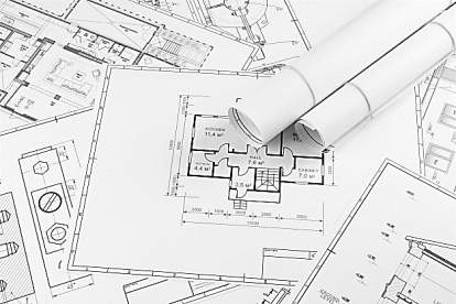
Drawing paper is made up of variety of qualities and manufactured in sheets or rolls. White drawing papers that will not turn yellow with age or exposure are used for finished drawings, maps, charts, and drawings for photographic reproduction. For pencil layouts and working drawings buff detail papers are preferred as they are easier on the eyes compared to white papers.
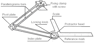
Mini drafter is used for drawing horizontal lines, vertical lines, inclined lines, angles, parallel lines, perpendicular lines etc. A Mini Drafter or drafting machine is a tool used in technical drawing, consisting of a pair of scales mounted to form a right angle on an articulated protractor head that allows an angular rotation.
The protractor head (two scales and protractor mechanism) is able to move freely across the surface of the drawing board, sliding on two guides directly or indirectly anchored to the drawing board. These guides, which act separately, ensure the movement of the set in the horizontal or vertical direction of the drawing board, and can be locked independently of each other.
Typically, the machine is mounted on a drawing board with a hard and smooth surface, anchored to a base that allows its tilting and lifting. Thus, the realization of a drawing can be achieved in the most convenient way on a working surface that can be tilted at any angle from horizontal to vertical.
The basic instrument is the graphite lead pencil, made in various hardness’s. Each manufacturer has special methods of processing design to make the lead strong and yet give a smooth clear line.
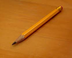
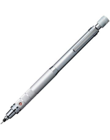
In the left there is an ordinary pencil, with the lead set in wood and the other is a semi-automatic pencil with thinner leads. Both are fine but have the disadvantage that in use, the wood must be cut away to expose the lead (a time-consuming job), and the pencil becomes shorter and shorter until the last portion of it is to be discarded. Whereas semi automatic pencils, with a chuck to clamp andhold the lead, are moreconvenient, has a plastic handle and changeable tip (for indicating the grade of lead).
Drawing pencils are graded by numbers and letters from 6B which is very soft and black, to 5B, 4B, 3B, 2B, B, and HB to F, the medium grade; then H, 2H, 3H, 4H, 5H, 6H, 7H, and 8H to 9H, the hardest. The soft (B) grades are used primarily for sketching and rendered drawings and the hard (H) grades for instrument drawings.
Engineering drawings are prepared on standard size drawing sheets. The correct shape and sizeof the object can be visualized from the understanding of not only its views but also from thevarious types of lines used, dimensions, notes, scale etc. For uniformity, the drawings must bedrawn as per certain standard practice.
Drawing paper layout
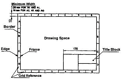
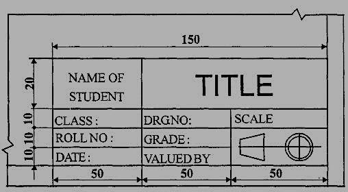
The layout of a drawing sheet used on the shop floor is shown in Fig.1. The layout suggested to students is shown in Fig.2.
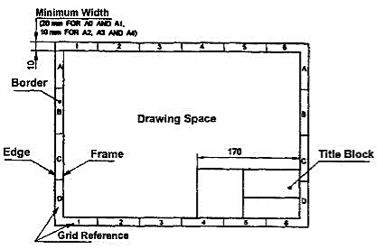
Figure: General features of a drawing sheet
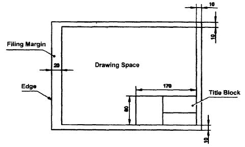
Figure: Layout of sheet for a class work
i) Sizes of Drawing Sheets
The standard drawing sheet sizes are arrived at on the basic Principal of x: y = 1: and xy = 1 where x and yare the sides of the sheet. For example, A0, having a surfacearea of 1 Sq. m; x = 841 mm and y = 1189 mm. The successive sizes are obtained by either byhalving along the length ordoubling the width, the area being in the ratio 1: 2. Designation of sizes is given in Fig.3 and their sizes are given in Table 1. For class work use of A2 size drawingsheet is preferred.
Designation | Dimension, mm (Trimmed size) |
A0 | 841 × 1189 |
A1 | 594 × 841 |
A2 | 420 × 594 |
A3 | 297 × 420 |
A4 | 210 × 297 |
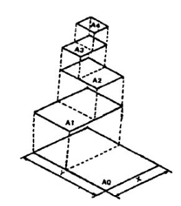
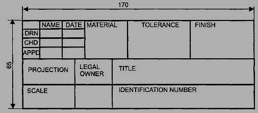
The title block should lie within the drawing space at the bottom right hand comer of the sheet. The title block can have a maximum length of 170 mm providing the following information.
1. Title of the drawing.
2. Drawing number.
3. Scale.
4. Symbol denoting the method of projection.
5. Name of the firm, and
6. Initials of staff who have designed, checked and approved.
The title block used on shop floor and one suggested for student’s class work are shown inFig.4& Fig. 5.
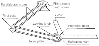
Figure: Shop floor drawing sheet layout
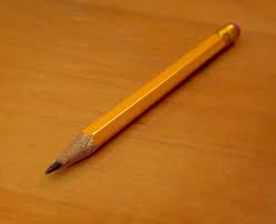
Figure: Students class work
Just as in English textbook the correct words are used for making correct sentences; in EngineeringGraphics, the details of various objects are drawn by different types of lines. Each line has adefinite meaning and sense toconvey.
IS 10714 (Pint 20): 2001 (General principles of presentation on technical drawings) and SP 46:2003specify the following types of lines and their applications:
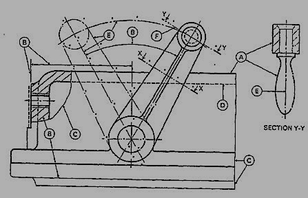
1. Visible Outlines, Visible Edges: (Continuous wide lines) the lines drawnto represent the visible outlines/ visible edges / surface boundary lines of objects should beoutstanding in appearance.
2. Dimension Lines: (Continuous narrow Lines) Dimension Lines are drawnto mark dimension.
3. Extension Lines: (Continuous narrow Lines)There are extended slightly beyond therespective dimension lines.
4. Construction Lines: (Continuous narrow Lines) Construction Lines are drawn forconstructing drawings and should not be erased aftercompletion of the drawing.
5. Hatching / Section Lines: (Continuous Narrow Lines)
Hatching Lines are drawn for the sectioned portion of an object. These are drawn inclinedat an angle of 45° to the axis or to the main outline of the section.
6. Guide Lines: (Continuous Narrow Lines)
Guide Lines are drawn for lettering and should not be erased after lettering.
7. Break Lines: (Continuous Narrow Freehand Lines)
Wavy continuous narrow line drawn freehand is used to represent break of an object.
8. Break Lines: (Continuous Narrow Lines with Zigzags)
Straight continuous arrow line with zigzags is used to represent break of an object.
9. Dashed Narrow Lines: (Dashed Narrow Lines)
Hidden edges / Hidden outlines of objects are shown by dashed lines of short dashes ofequal lengths of about 3 mm, spaced at equal distances of about 1 mm. the points of intersectionof these lines with the outlines / another hidden line should be clearly shown.
10. Center Lines: (Long-Dashed Dotted Narrow Lines)
Center Lines are drawn at the center of the drawings symmetrical about an axis or both theaxes. These are extended by a short distance beyond the outline of the drawing.
11. Cutting Plane Lines:
Cutting Plane Line is drawn to show the location of a cutting plane. It is long-dashed dottednarrow line, made wide at the ends, bends and change of direction. The direction of viewingis shown by means of arrows resting on the cutting plane line.
12. Border Lines
Border Lines are continuous wide lines of minimum thickness 0.7 mm.
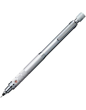
Figure: Types of lines
Table 2 Types of lines and their applications
Line | Description | General application |
| Continuous thick or continuous wide | Visible outlines, visible edges, main representation in diagrams, maps; system lines |
| Continuous thin (narrow) (straight or curved) | Imaginary lines of intersection; grid, dimension. Extension, projection, reference lines and hatching. |
| Continuous thin (narrow) freehand. | Limits of partial or interrupted views and sections, if the limit is not a chain thin line. |
| Continuous thin (narrow) with zigzags (straight) | Long break line |
| Dashed thick (wide) | Line showing permissible of surface treatment. |
| Dashed thin (narrow) | Hidden outline; hidden edges |
| Chain thin Long-dashed dotted (narrow) | Centre line; lines of symmetry; trajectories; pitch circle of gears, pitch circle of holes. |
| Chain thick or long - dashed (dotted) wide | Indication of lines or surfaces to which a special requirement applies. |
Line widths:
Line width means line thickness
Choose line widths according to the size of the drawing from the following range: 0.13, 0.18, 0.25, 0.35, 0.5, 0.7 and 1 mm.
Precedence of Lines
1. When a Visible Line coincides with a Hidden Line or Center Line, draw the Visible Line.Also, extend the Center Line beyond the outlines of the view.
2. When a Hidden Line coincides with a Center Line, draw the Hidden Line.
3. When a Visible Line coincides with a Cutting Plane, draw the Visible Line.
4. When a Center line coincides with a Cutting Plane, draw the Center Line and show the
Cutting Plane line outside the outlines of the view at the ends of the Center Line by thickdashes.
Graphic representation of the shape of a part, machine, or structure gives one aspect of the information needed for its construction. To this must be added, to complete the description, figured dimensions, notes on material and finish, and a descriptive title—all lettered, freehand, in a style that is perfectly legible, uniform, and capable of rapid execution. As far as the appearance of a drawing is concerned, the lettering is the most important part. But the usefulness of a drawing, too, can be ruined by lettering done ignorantly or carelessly, because illegible figures are apt to cause mistakes in the work.
By far the greatest amount of lettering on drawings is done in a rapid single-stroke letter, either vertical or inclined, and every engineer must have absolute command of these styles.
The term "single-stroke," or "one-stroke," does not mean that the entire letter is made without lifting the pencil or pen but that the width of the stroke of the pencil or pen is the width of the stem of the letter.
Always draw light guide lines for both tops and bottoms of letters, using a sharp pencil. Figure 1 shows a method of laying off several equally spaced lines. Draw the first base line; then set the bow spacers to the distance wanted between base lines and step off the required number of base lines. Above the last line mark the desired height of the letters.
Good technique is as essential in lettering as in drawing. The quality of the lettering is important whether it appears on finished work to be reproduced by one of the printing processes or as part of a pencil drawing to be inked. In the first case, the penciling must be clean, firm, and opaque; in the second, it may be lighter.
Drawing of a component, in addition to providing complete shape description, must also furnish information regarding the size description. These are provided through the distances between the surfaces, location of holes, nature of surface finish, type of material, etc. The expression of these features on a drawing, using lines, symbols, figures and notes is called dimensioning.
Principles of Dimensioning
Some of the basic principles of dimensioning are given below.
1. All dimensional information necessary to describe a component clearly and completely shall be written directly on a drawing.
2. Each feature shall be dimensioned once only on a drawing, i.e., dimension marked in one view need not be repeated in another view.
3. Dimension should be placed on the view where the shape is best seen (Fig.7)
4. As far as possible, dimensions should be expressed in one unit only preferably in millimeters, without showing the unit symbol (mm).
5. As far as possible dimensions should be placed outside the view (Fig. 8).
6. Dimensions should be taken from visible outlines rather than from hidden lines (Fig. 9).

7. No gap should be left between the feature and the start of the extension line (Fig.).
Figure: Marking of Extension lines
8. Crossing of center lines should be done by a long dash and not a short dash (Fig.11).
Figure: Crossing of Centre lines
Execution of dimensions:
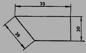
1. Projection and dimension lines should be drawn as thin continuous lines. Projection lines should extend slightly beyond the respective dimension line. Projection lines should be drawn perpendicular to the feature being dimensioned. If the space for dimensioning is insufficient, the arrow heads may be reversed, and the adjacent arrow heads may be replaced by a dot (Fig.). However, they may be drawn obliquely, but parallel to each other in special cases, such as on tapered feature (Fig.13).

Figure: Dimensioning in narrow spaces
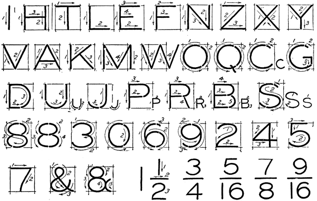
Figure: Dimensioning a tapered feature
2. A leader line is a line referring to a feature (object, outline, dimension). Leader lines should be inclined to the horizontal at an angle greater than 30°. Leader line should terminate,
(a) with a dot, if they end within the outline of an object (Fig.2.21a).
(b) with an arrow head, if they end on outside of the object (Fig.2.21b).
(c) without a dot or arrow head, if they end on dimension line (Fig.2.21c).
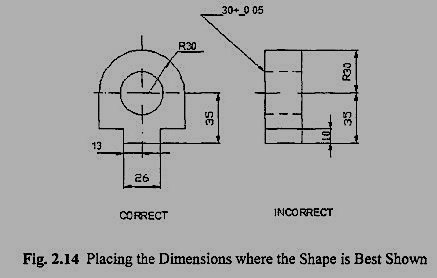
Figure: Termination of leader lines
Dimension Termination and Origin Indication
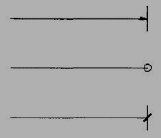
Dimension lines should show distinct termination in the form of arrow heads or oblique strokes or where applicable an origin indication (Fig.15). The arrow head included angle is 15°. The origin indication is drawn as a small open circle of approximately 3 mm in diameter. The proportion length to depth 3: 1 of arrow head is shown in Fig.16.
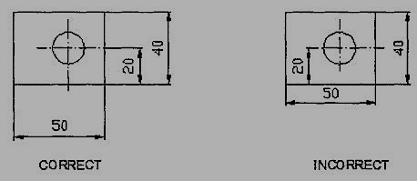
Figure: Termination of dimension lines
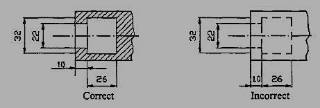
Figure: Proportions of an arrow head
Methods of Indicating Dimensions
The dimensions are indicated on the drawings according to one of the following two methods.
Method I (Aligned method)
Dimensions should be placed parallel to and above their dimension lines and preferably at the middle, and clear of the line. (Fig. 17).
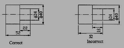
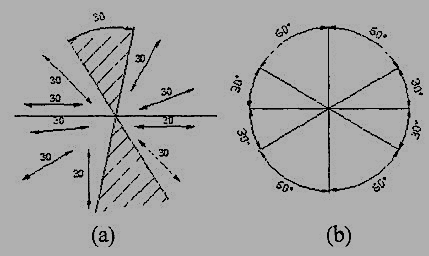
Dimensions may be written so that they can be read from the bottom or from the right side of the drawing. Dimensions on oblique dimension lines should be oriented as shown in Fig.18a and except where unavoidable, they shall not be placed in the 30° zone. Angular dimensions are oriented as shown in Fig.18b.
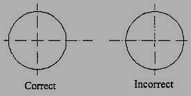
Figure: Angular dimensioning
Method 2(Uni-directional method)
Dimensions should be indicated so that they can be read from the bottom of the drawing only. Non-horizontal dimension lines are interrupted, preferably in the middle for insertion of the dimension (Fig.19a).
Angular dimensions may be oriented as in Fig.19b

Figure: Uni-directional method
Simple Geometrical constructions
Engineering drawing consists of many geometrical constructions. A few methods are illustrated here without mathematical proofs.
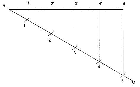
1. To divide a straight line into a given number of equal parts say 5.
construction (Fig.)
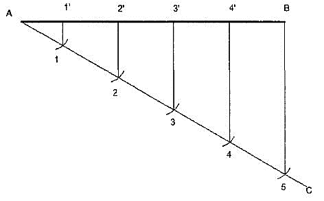
Figure Dividing a line
i. Draw AC at any angle θ to AB.
ii. Construct the required number of equal parts of convenient length on AC like 1,2,3.
iii. Join the last point 5 to B
iv. Through 4, 3, 2, 1 draw lines parallel to 5B to intersect AB at 4',3',2' and 1'.
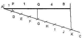
2. To divide a line in the ratio 1: 3: 4.
Construction (Fig. 21)
As the line is to be divided in the ratio 1:3:4 it must be divided into 8 equal divisions. By following the previous example divide AC into 8 equal parts and obtain P and Q to divide the line AB in the ratio 1:3:4.

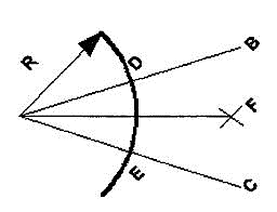
3. To bisect a given angle.
Construction (Fig.)

1. Draw a line AB and AC making the given angle.
2. With center A and any convenient radius R draw an arc intersecting the sides at D and E.
3. With centers D and E and radius larger than half the chord length DE, draw arcs intersecting at F.
4. Join AF, <BAF = <PAC.
1. Parallel projections
i Orthographic projections
ii. Oblique Projections
2. Perspective projection
Parallel projections
It is a type of projection the line of the 3D object never intersects with each other.
i Orthographic
A way to show the object in 2D plan surface in which the projection line are perpendicular to surface. are drawn as multi view drawings, which show flat representations of principal views of the subject. Orthographic drawings are useful especially when a design has been developed to a stage whereby it is almost ready to manufacture.
Multiview
When more than one projection planes are used the result is multiview projection. It has the quality that these views are arranged in systematic manner so that reader can conceptualize it easily. They also called 1st angle projections or 3rd angle projections.
Axonometric
Axonometric means to measure along axes. This type of projections used to draw an object when it is rotated along one or more of its axes relative to the plane of projection it has 3types 1) Isometric 2) Dimetric 3) Trimetric.
Isometric
drawings consist of two-dimensional drawings that are tilted at some angle to expose other views and give the viewer the illusion that what he or she is viewing is a three-dimensional drawing. The way to draw 3D view of an object in which the horizontal edge is drawn on the 30° angle and vertical are perpendicular from horizontal base.
ii. Oblique
Projection is a simple type of technical drawing of graphical projection used for producing two-dimensional (2D) images of three-dimensional (3D) objects. Oblique projection is commonly used in technical drawing.
We have assumed the object to be situated in front of the V.P. and above the H.P. i.e., in the first quadrant and then projected it on these planes. This method of projection is known as first-angle projection method. The object lies between the observer and the plane of projection. In this method, when the views are drawn in their relative positions, the top view comes below the front view. In other words, the view seen from above is placed on the other side of (i.e. below) the front view. Each projection shows the view of that surface (of the object) which is remote from the plane on which it is projected, and which is nearest to the observer.
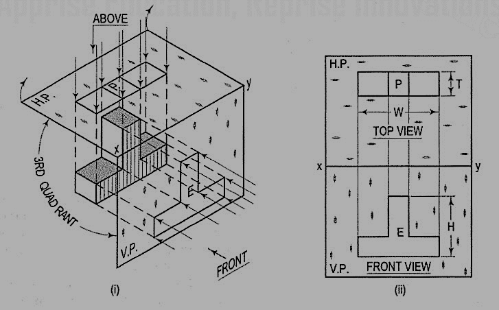
In this method of projection, the object is assumed to be situated in the third quadrant [fig. 11(a)]. The planes of projection are assumed to be transparent. They lie between the object and the observer. When the observer views the object from the front, the rays of sight intersect the V.P. The figure formed by joining the points of intersection in correct sequence is the front view of the object. The top view is obtained in a similar manner by looking from above. When the two planes are brought in line with each other, the views will be shown in fig.11 (b). The top view in this case comes above the front view.
A point may be situated, in space, in any one of the four quadrants formed by the two principal planes of projection or may lie in any one or both. Its projections are obtained by extending projectors perpendicular to the planes.
One of the planes is then rotated so that the first and third quadrants are opened out. The projections are shown on a flat surface in their respective positions either above or below or in xy.
1. If a point is situated in the first quadrant
The pictorial view [fig. 14 (i)] shows a point A situated above the H.P. and in front of the V.P., i.e., in the first quadrant. a' is its front view and the top view. After rotation of the plane, these projections will be shown in fig. 14 (ii).
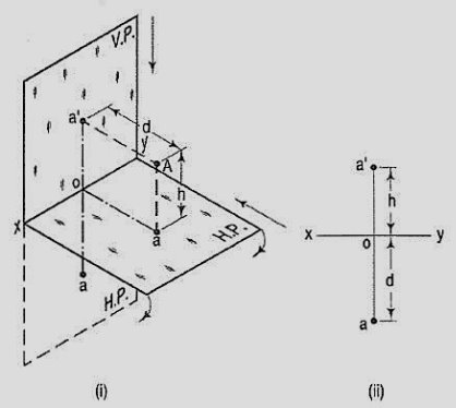
The front views a' is above xy and the top view a below it. The line joining a' and a (which also is called a projector), intersects xy at right angles at a point o. It is quite evident from the pictorial view that a'o = Aa, i.e., the distance of the front view from xy = the distance of A from the H.P. viz. h. Similarly, ao = Aa’, i.e., the distance of the top view from xy = the distance of A from the V.P. viz. d.
2. If a point is situated in second quadrant
A point B (fig. 15) is above the H.P. and behind the V.P., i.e., in the second quadrant. b' is the front view and b the top view. When the planes are rotated, both the views are seen above xy. Note that b'o = Bb and bo = Bb'.
3. If a point is situated in third quadrant
A point C (fig. 16) is below the H.P. and behind the Y.P., i.e., in the third quadrant. Its front view c' is below xy and the top view c above xy. Also, c'o = Cc and co = Cc'.
4. If a point is situated in 4th quadrant
A point f (fig.) is below the H.P. and in front of the V.P., i.e., in the fourth quadrant. Both its projections are below xy, and e'o = Ee and eo = Ee'.

General conclusions:
1. The fine joining the top view and the front view of a point is always perpendicular to xy. It is called a projector.
2. When a point is above the H.P., its front view is above xy; when it is below the H.P., the front view is below xy. The distance of a point from the H.P. is shown by the length of the projector from its front view to xy.
3. When a point is in front of the V.P., its top view is below xy; when it is behind the V.P., the top view is above xy. The distance of a point from the V.P. is shown by the length of the projector from its top view to xy.
4. When a point is in a reference plane, its projection on the other reference plane is in xy.
Examples:
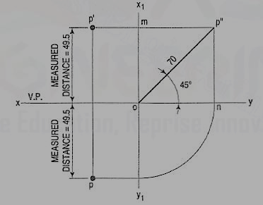
1. A point P is in the first quadrant. Its shortest distance from the intersection point of H.P., V.P. and Auxiliary vertical plane, perpendicular to the H.P. and V.P. is 70 mm and it is equidistant from principal planes (H.P. and V.P.). Draw the projections of the point and determine its distance from the H.P. and V.P.
Note: ‘O’ represents intersection of H.P., V.P. and A.V.P.
Drawing steps:
1. Draw xy and x1 y1 perpendicular reference lines.
2. ‘O’ represents intersection of H.P., V.P. and A.V.P.
3. Draw from O a line inclined at 45° of 70 mm length.
4. Project from P" on xy line and x1 y1. The projections are n and m respectively as shown in figure. From O draw arc intersecting x1 y1.
5. Draw a parallel line at convenient distance from x1 y1. Extend P"m to intersect
a parallel line at p' and p as shown.
6. Measure distance from xy line, which is nearly 49.4974 mm say 49.5 mm.
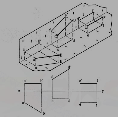
Line AB is in the H.P. Its top view ab is equal to AB; its front view a' b' is in xy.
Line CD is in the V.P. Its front view c'd' is equal to CO; its top view cd is in xy.
Line ff is in both the planes. Its front view e' f' and the top view if coincide with each other in xy.
Hence, when a line is contained by a plane, its projection on that plane is equal to its true length; while its projection on the other plane is in the reference line.
When the line is inclined to one plane and parallel to the other, the trace of the line is obtained only on the plane to which it is inclined, and no trace is obtained on the plane to which it is parallel.
When a plane is parallel to a reference plane, it has no trace on that plane. Its trace on the other reference plane, to which the earlier reference plane is perpendicular, is parallel to xy reference line.
(a) Line AB is parallel to the H.P.
a and b are the top views of the ends A and B respectively. It can be clearly seen that the figure ABba is a rectangle. Hence, the top view ab is equal to AB.
a'b' is the front view of AB and is parallel to xy.
(b) Line CD is parallel to the V.P. The line c'd' is the front view and is equal to CD; the top view cd is parallel to xy.
(c) Line ff is parallel to the H.P. and the V.P. ef is the top view and e'f' is the front view; both are equal to ff and parallel to xy.
Hence, when a line is parallel to a plane, its projection on that plane is equal to its true length; while its projection on the other plane is parallel to the reference line.
When a line is perpendicular to one reference plane, it will be parallel to the other.
(a) Line AB is perpendicular to the H.P. The top views of its ends coincide in the point a. Hence, the top view of the line AB is the point a. Its front view a' b' is equal to AB and perpendicular to xy.
(b) Line CD is perpendicular to the V.P. The point d' is its front view and the line cd is the top view. cd is equal to CD and perpendicular to xy.
Hence, when a line is perpendicular to a plane its projection on that plane is a point; while its projection on the other plane is a line equal to its true length and perpendicular to the reference line.
In first-angle projection method, when top views of two or more points coincide, the point which is comparatively farther away from xy in the front view will be visible; and when their front views coincide, that which is farther away from xy in the top view will be visible.
In third-angle projection method, it is just the reverse. When top views of two or more points coincide the point, which is comparatively nearer xy in the front view will be visible; and when their front views coincide, the point which is nearer xy in the top view will be visible.
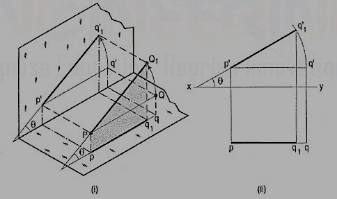
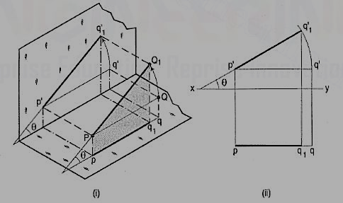
The inclination of a line to a plane is the angle which the line makes with its projection on that plane.
Line PQ1 [fig. (i)] is inclined at an angle 8 to the H.P. and is parallel to the V.P. The inclination is shown by the angle 8 which PQ1 makes with its own projection on the H.P., viz. the top view pq1.
The projections [fig.(ii)] may be drawn by first assuming the line to be parallel to both the H.P. and the V.P. Its front view p'q' and the top view pq will both be parallel to xy and equal to the true length. When the line is turned about the end P to the position PQ1 so that it makes the angle 8 with the H.P. while remaining parallel to the V.P., in the front view the point q' will move along an arc drawn with p' as center and p'q' as radius to a point q'1 so that p'q'1 makes the angle 8 with xy. In the top view, q will move towards p along pq to a point q1 on the projector through q'1. p'q'1 and pq1 are the front view and the top view respectively of the line PQ1.
Line inclined to both the planes:
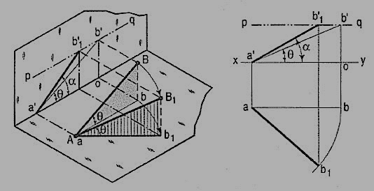
A line AB (fig. 23) is inclined at θ to the H.P. and is parallel to the V.P. The end A is in the H.P. AB is shown as the hypotenuse of a right-angled triangle, making the angle θ with the base.
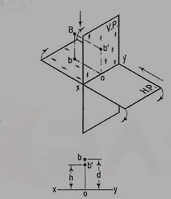
The top view ab is shorter than AB and parallel to xy. The front view a'b' is equal to AB and makes the angle θ with xy.
Keeping the end, A fixed and the angle θ with the H.P. constant, if the end B is moved to any position, say B1, the line becomes inclined to the V.P. also.
In the top view, b will move along an arc, drawn with a as center and ab as radius, to a position b1. The new top view ab1 is equal to ab but shorter than AB.
In the front view, b' will move to a point b'1 keeping its distance from xy constant and equal to b'o; i.e., it will move along the line pq, drawn through b' and parallel to xy. This line pq is the locus or path of the end B in the front view. b'1 will lie on the projector through b1. The new front view a'b'1 is shorter than a'b' (i.e., AB) and makes an angle a with xy. a is greater than θ.
Thus, if the inclination θ of AB with the H.P.is constant, even when it is inclined to the V.P.
(i) its length in the top view, viz. ab remains constant; and
(ii) the distance between the paths of its ends in the front view, b’o remains constant.
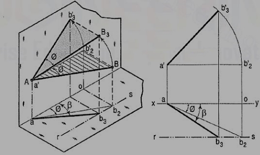
b) The same line AB (fig. 24) is inclined at ϕ to the V.P. and is parallel to the H.P. Its end A is in the V.P. AB is shown as the hypotenuse of a right-angled triangle making the angle ϕ with the base.
The front view a'b'2 is shorter than AB and parallel to xy. The top view ab2 is equal to AB and makes an angle ϕ with xy.
Keeping the end, A fixed and the angle ϕ with the V.P. constant, if B is moved to any position, say B3, the line will become inclined to the H.P. also.
In the front view, b'2, will move along the arc, drawn with a' as center and a'b'2 as radius, to a position b'3. The new front view a'b'3 is equal to a'b'2 but is shorter than AB.
In the top view, b2 will move to a point b3 along the line rs, drawn through b2 and parallel to xy, thus keeping its distance from the path of a, viz. b2o constant. rs is the locus or path of the end B in the top view. The point b3 lies on the projector through b'3. The new top view ab3 is shorter than ab2 (i.e. AB) and makes an angle β with xy. β is greater than ϕ.
Here also we find that, if the inclination of AB with the V.P. does not change, even when it becomes inclined to the H.P.
(i) its length in the front view, viz. a'b'2 remains constant; and
(ii) the distance between the paths of its ends in the top view, viz. b2o remains constant.
Hence, when a line is inclined to both the planes, its projections are shorter than the two length and inclined to xy at angles greater than the true inclinations. These angles viz. α and β are called apparent angles of inclination.
When the line is inclined to one plane and parallel to the other, the trace of the line is obtained only on the plane to which it is inclined, and no trace is obtained on the plane to which it is parallel.
When a line is inclined to a plane, it will meet that plane, produced if necessary. The point in which the line or line-produced meets the plane is called its trace.
The point of intersection of the line with the H.P. is called the horizontal trace, usually denoted as H.T. and that with the V.P. is called the vertical trace or V.T.
Refer to fig. 25.
(i) A line AB is parallel to the H.P. and the V.P. It has no trace.
(ii) A line CD is inclined to the H.P. and parallel to the V.P. It has only the H.T. but no V.T.
(iii) A line ff is inclined to the V.P. and parallel to the H.P. It has only the V.T. but no H.T.
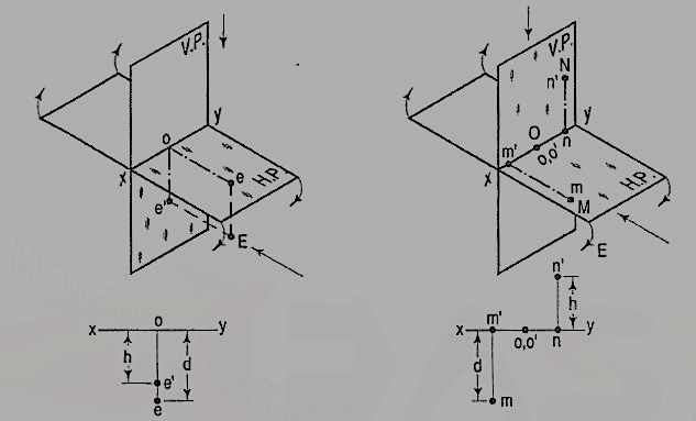
Thus, when a line is parallel to a plane it has no trace upon that plane.
(i) A line PQ is perpendicular to the H.P. Its H.T. coincides with its top view which is a point. It has no V.T.
(ii) A line RS is perpendicular to the V.P. Its V.T. coincides with its front view which is a point. It has no H.T.
Hence, when a line is perpendicular to a plane, its trace on that plane coincides with its projection on that plane. It has no trace on the other plane.
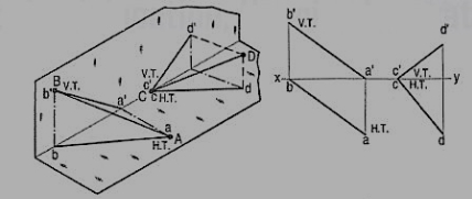
(i) A line AB has its end A in the H.P. and the end B in the V.P. Its H.T. coincides with the top view of A and the V.T. coincides with b' the front view of B.
(ii) A line CD has its end C in both the H.P. and the V.P. Its H.T. and V.T. coincide with c and c' (the projections of C) in xy. Hence, when a line has an end in a plane, its trace upon that plane coincides with the projection of that end on that plane.
Methods of determining traces of a line:
Method I:
Fig. 28 (i) shows a line AB inclined to both the reference planes. Its end A is in the H.P. and 8 is in the V.P. a'b' and ab are the front view and the top view respectively [fig. 28 (ii)].
The H.T. of the line is on the projector through a' and coincides with a. The V.T. is on the projector through b and coincides with b'.
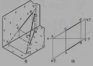
Let us now assume that AB is shortened from both its ends, its inclination with the planes remaining constant. The H.T. and V.T. of the new line CD are still the same as can be seen clearly in fig. 29 (i). c'd' and cd are the projections of CD [fig. 29 (ii)]. Its traces may be determined as described below.
(i) Produce the front view c'd' to meet xy at a point h.
(ii) Through h, draw a projector to meet the top view cd-produced, at the H.T. of the line.
(iii) Similarly, produce the top view cd to meet xy at a point v.
(iv) Through v, draw a projector to meet the front view c'd'-produced, at the V.T. of the line.
Method II:
c'd' and cd are the projections of the line CD [fig. 30 (ii)]. Determine the true length C1D1 from the front view c'd' by trapezoid method. The point of intersection between c'd'-produced and C1D1-produced is the V.T. of the line.
Similarly, determine the true length C2D2 from the top view ed. Produce them to intersect at the H.T. of the line.
Examples:
1. A line AB 50 mm long, has its end A in both the H.P. and the V.P. It is inclined at 30° to the H.P. and at 45° to the V.P. Draw its projections.
As the end A is in both the planes, its top view and the front view will coincide in xy.
(i) Assuming AB to be parallel to the V.P. and inclined at θ (equal to 30°) to the H.P., draw its front view ab' (equal to AB) and project the top view ab.
(ii) Again, assuming AB to be parallel to the H.P. and inclined at ϕ (equal to 45°) to the V.P., draw its top view ab1 (equal to AB). Project the front view ab'1.
ab and ab'1 are the lengths of AB in the top view and the front view respectively, and pq and rs are the loci of the end B in the front view and the top view respectively.
(iii) With a as center and radius equal to ab'1, draw an arc cutting pq in b'2. With the same center and radius equal to ab, draw an arc cutting rs in b2.
Draw lines joining a with b'2 and b2. ab'2 and ab2 are the required projections.
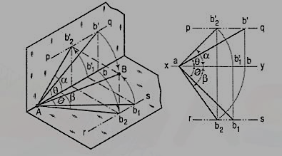
Fig. shows in pictorial and orthographic views, the solution obtained with all the above steps combined in one figure only.
References:
1. A Text Book of Engineering Drawing: RK Dhawan, S Chand & Company
2. Engineering Drawing Plane and Solid Geometry: N.D. Bhatt, Charotar Publishing House.


