UNIT – 4
NUCLEAR & ELEMENTARY IDEA OF PARTICLE PHYSICS
4.1.1 Charged particles with matter
A fast charged particle loses energy via the action of its electric field on the atoms it encounters as it passes through matter. In most cases, nearly all the energy is lost to electron. Both nuclei and electrons feel the coulomb forces due to the transient field, but the impulse, exerted as the ion passes by, transfer momentum and the much smaller mass of the electrons means it carry away much more energy than heavy nucleus. Also unless the energy is very high, nuclear collision are rare for most of ions and have little effect on overall energy loss process.
In a head-on collision with an ion of mass M and energy E, an electron (mass m << M) initially at rest emerges with a speed approximately twice that of the incident ion and its energy will be
 E = E(4m/ M)
For a 4-MeV  particle, this is about 2.2 keV. In general, the average energy loss will be much less than this. However, even this maximum energy transfer is small compared with E, and many collisions must occur before the ion comes to rest.
The heavy particle is deflected very little by these interactions with electrons and moves in an almost straight line during the slowing-down process. Fluctuations in its energy loss tend to average out and it will have a definite range depending on its energy, mass, charge and the nature of the stopping medium. The particle ionizes and excites many atoms in its passage through the stopping material. Also, the more energetic, recoiling electrons (known as delta rays) cause further ionization, generating more secondary electrons as they in turn lose their energy. The result is a trail of ionization and excitation of atoms and molecules along the path of the moving particle. This excitation and ionization in the medium is used to detect charged particles.
Charged particles mainly interact with matter through Coulomb forces with the orbital electrons within the absorber atoms. Entering the medium, the charged particle immediately interacts simultaneously with many electrons. In any one such encounter, the electron feels an impulse from the Coulomb force as the particle passes its vicinity.
Depending on the proximity of the encounter, this impulse may be sufficient either to raise the electron to a higher shell: excitation/ soft collision or to remove it completely from the atom : ionization/ hard collision.
In some hard collisions, enough energy is transferred to the electrons such that the electron itself causes substantial secondary ionization.
Interactions of the particles with nuclei occur rarely (not significant in the detector response). Typically σinel ~ 10-16 cm2 >> σnucl scatt ~ 10-24 cm2 (barn) dominant energy loss due to atomic electron collisions
4.1.2 Gamma-rays with matter
Photon’s lack of an electric charge makes impossible the many inelastic collisions with atomic electrons so characteristic of charged particles. They are many times more penetrating in matter than charged particles. A beam of photons is not degraded in energy as it passes through a thickness of matter, only attenuated in intensity. They interact with matter in mainly three ways, one dominant over other depending on the γ-ray energy. Three ways are
All these processes lead to the partial or complete transfer of the γ-ray photon energy to electron energy. Each of the interaction processes removes the γ-ray photon from the incident direction either by absorption or by scattering away. The probability that the γ-ray photon is removed from the beam is called linear attenuation coefficient μ and is given by
I(x) =Ioe-μx
Where μ= Nσ,
N: no. density of atoms,
σ: total interaction cross section

Figure 1: Attenuation of a beam of gamma radiation through an absorber of thickness x
Photoelectric absorption: the absorption of a photon by an atomic electron with the subsequent ejection of the electron from the atom. Outgoing electron energy E= hν– B.E. B.E is binding energy of the electron. Since a free electron cannot absorb a photon and also conserve momentum, photoelectric effect always occurs on bound electrons with the nucleus absorbing the recoil momentum. This is predominant mode of γ-interaction in all kinds of matter, especially the high-Z absorbers, at energies less than ~ 0.1 MeV. (Typical ionization potentials of K electrons are 2.3 keV ( Al ), 10 keV (Cu), and ~ 100 keV (Pb)).
The cross-section of photoelectric absorption is given by

v is the photoelectron speed, θ, φ are angles specifying the direction of photoelectron.
At energies above the highest electron BE of the atom (K shell), the cross section is relatively small but increases rapidly as the K-shell energy is approached. Just after this point, the cross section drops drastically (discontinuous jump) since the K-electrons are no longer available for the photoelectric effect (K absorption edge). Below this energy, the cross section rises once again and dips as the L, M levels etc are passed (L-absorption edges, M-absorption edge). The effect is more pronounced in the high-Z material.
Compton scattering: Interaction process of a γ-ray photon with a free electron in the absorbing material. If the photon energy is much higher than the binding energy of a bound electron, it can be considered to be a free electron. The incoming γ-ray photon is deflected through an angle θ w.r.t. to its original direction. The photon transfers a portion of its energy to the (recoil) electron. Because all angles are possible, the energy transfer vary from zero to a large fraction of the γ-ray energy.
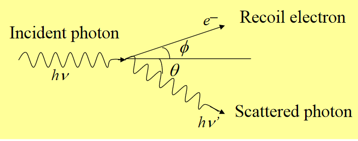
Figure 2: Compton scattering
For θ ≅0, very little energy transferred,
θ ≅ π , maximum energy transferred (γ-ray backscattered)
The sharp drop at the maximum recoil energy : Compton edge
The cross-section of Compton scattering is given by Klein-Nishina formula:
 /dQ= Z ro2 [ 1/ 1+α(1-cos
  2 [ (1+cos 2
  /2] [ 1 + α 2(1-cos
  ) 2 / (1 + cos 2
  )[ 1+α(1-cos
 0] ]
0] ]
Where α =hν/mc2, measure of the photon energy in units of the electron rest mass energy and r0= e2/mc2 is the classical electron radius
At any given α the angular distribution is peaked in the forward direction. As αincreases, the forward peaking becomes more pronounced. The deviation from Thomson scattering is largest at large scattering angles. In practice the Klein-Nishina cross section has been found to be in excellent agreement with experiments at least out to hν= 10 mc2.
Pair production: Transformation of a photon into an electron-positron pair. To conserve momentum, this can only occur in the presence of a third body, usually a nucleus. To create the pair the photon must have at least an energy of 1.022 MeV. Any excess energy carried by the photon goes into the kinetic energy shared by the pair.
This positron subsequently annihilates after slowing down in the absorbing medium. For typical energies, both the e─ and e+ travel a few mm before losing all the kinetic energy. At this point the e+ combines with an e─ and two annihilation photons (0.511 MeV each) are produced, virtually in coincidence with the pair production interaction. The probability of pair production per nucleus ∞Z2 of the absorber material and rises sharply with energy.
Key Takeaways
Ionization chamber
One of the simplest detectors conceptually is the ionization chamber, which measures the ionization produced when charged particles pass through a gas.
Ionization chamber is shown in Figure 3(a). it consists of two electrodes forming a parallel-plate capacitor (capacity C) between which a voltage is applied, normally through a large bias resistor R. The electric field, which is set high enough to prevent recombination, sweeps electrons to the anode and positive ions much more slowly to the cathode. The resulting current is proportional to the rate of production of ionization between the plates. The average energy required to ionize a gas atom or molecule depends on the gas, but, except for helium, it is about 30eV per ion pair. In air, for example, it is 34eV per ion pair. Thus, if particles entering an air-filled detector deposit an average of 1 GeVs-1 in the gas, the average current flowing through the chamber will be

which is measurable with a sensitive electrometer.
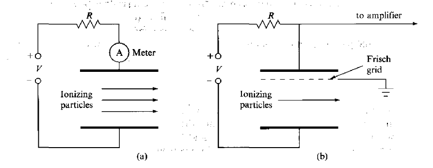
Figure 3: Ionization chamber (a) simple plate geometry (b) with the addition of Frisch grid for pulse counting
A single, charged particle entering the detector will produce a pulse of current and, if the time constant RC is large compared with the pulse duration, there will be a change in the voltage on the chamber as the electrons and ions are collected.
The total voltage change is q/C, where q is the charge collected. For example, the capacity of a chamber with electrodes 10 cm x 10 cm, separated by 2 cm, is about 4.5 pF and, if a 5-MeV  particle is stopped in it, the voltage pulse will be about 5 mV. This is rather small and must be amplified considerably before it can be analysed with conventional electronics.
As the electrons and ions move towards their respective electrodes under the influence of the applied field, they undergo many collisions with gas atoms or molecules on the way and quickly acquire drift velocities which depend on the voltage gradient.
For a voltage gradient of 100 V cm-1, ions move at about 1 m in air at STP and would take about 0.02 s to cross the 2 cm gap. Electrons move about 1000 times faster and are collected very much more quickly.
The slow collection time for the positive ions means that the simple ionization chamber is not suitable for detecting individual particles (pulse operation) where a count rate of several kilohertz may be required.
However, a more serious complication arises because the time dependence of the voltage induced on the electrodes depends on the movement of the charges as they are collected. Electrons and ions move at very different speeds and, since the shape of the output pulse depends on the time taken for the electrons and ions to reach their respective electrodes, it also must depend on where the ionization was formed between the plates.
A chamber designed for pulse operation is the gridded ion chamber, shown in figure 3(b), which has a fine mesh, called a Frisch grid, placed close to the anode. This serves to screen the anode from the effects of the movement of charge within the main body of the chamber until the electrons reach the gap between the grid and anode.
The full pulse, measured between the grid and the anode, is then developed quite quickly and the shape of the voltage pulse is determined only by the electron transit time between the grid and anode, which, typically, is a few microseconds. The amplitude of the voltage pulse is proportional to the charge collected and, therefore, to the energy deposited in the gas.
The choice of detector gas is important and depends on a number of factors that influence the time and efficiency for collecting electrons. For example, while air is adequate for a detector used in continuous (current) mode, it is not suitable for pulse operation. This is because oxygen has a high electron affinity, which means that it has a high probability for capturing electrons and thus degrading the fast part of the electronic pulse. Common gases used for pulse operation include inert gases (helium, argon) and certain organic gases, such as isobutane.
Key Takeaways
A common way of amplifying the signal from a gas-filled detector is by increasing the electric field until electron can gain sufficient energy between collisions with gas atoms to cause further ionization.

Figure 4: Proportional counter
The original electrons and the newly released ones can then go on to produce further ionization, and a rapid amplification of the original cascade occurs in what is called a Townsend avalanche.
The multiplication factor can be large (103-105) and, if the field in the chamber is not too high, the size of the output pulse remains proportional to the amount of the original ionization. Such a chamber is called a proportional counter.
To make it easier to achieve the required field strength, the geometry is usually cylindrical, as shown in Figure, with a thin anode wire (radius a) and a concentric outer cylinder (inner radius b) forming the cathode. The electric field in such an arrangement varies radially according to the formula:
 = V / r ln b/a
Typical values for b and a are 10 and 0.01 mm and, with an applied voltage Vof 1 kV, the field is over 107 Vm-1 near the wire.
Since nearly all the ionization is produced close to the central wire where the electric field is strongest, the output pulse is independent of where the initial ionization occurs. Electron collection times (1-10 ns) are much more rapid than in the ionization chamber, which is important if timing information is required. Positive-ion collection times are still slow, however, and this limits the ultimate count rate at which the detector can be operated. The variation of the logarithm of pulse height with applied voltage V for a gas detector is sketched in Figure 5. Two curves are shown in the figure corresponding to different amounts of energy deposited in the gas. Initially, the output signal increases with V as recombination of ions and electrons in the gas is reduced. This is followed by a plateau region where there is full charge collection and the output is independent of V. As the voltage is increases, charge multiplication begins to occur and we enter the proportional region where the output pulse increases rapidly with voltage, but still is a measure of the energy deposited in the detector. At the upper end, the proportionality of the output deposited energy becomes progressively weaker until, finally a point is reached where the output is very large, but become independent of the input energy. This is the region where the Geiger Mueller is operated.
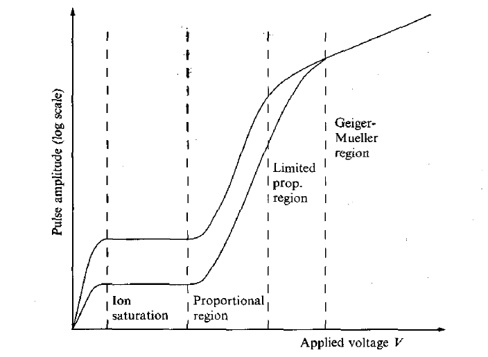
Figure 5: Variation of output signal from a gas filled ionization chamber as a function of applied voltage. Two curves correspond to different amount of energy deposited in the chamber.
Key Takeaways

A ‘particle detector’ to measure the ionizing radiation was developed by Geiger and Muller in the year 1928 and they called it a ‘Geiger Muller Counter’ which in short is known as the ‘GM counter.’
The G.M. Counter is a radiation detector. As Nuclear radiations emitted by disintegrating nuclei cannot be sensed directly. Indirect methods are employed to detect them.
PRINCIPLE
The ionizing particle passing through the tube ionizes the gas and electrons so produced move towards Anode. The velocity is quite high and they later produce secondary electrons after repeated collisions with the particles of the gas. These secondary electrons further produce more electrons in Geometric progression.
Due to this large multiplication action, a large ionization current is produced.
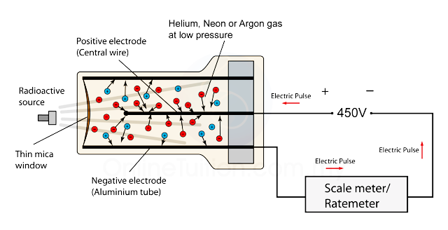
Figure 6: G. M. tube
CONSTRUCTION
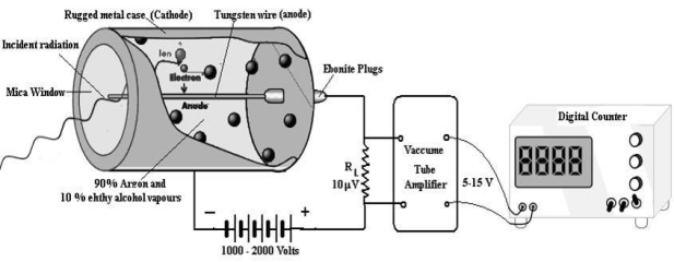
Figure 7: G. M counter laboratory assembly
A dc potential about 1200 volt is applied between the cathode and anode. When the radiation enters in the GM tube through the mica window it ionizes few argon atoms. If the applied voltage is strong enough, these ion produce a secondary avalanche that causes a current pulse. The current through RL produces a voltage pulse. This voltage is amplified up to 5 -15 Volt by vacuum tube amplifiers and is then applied to the counter. As each incoming radiation produces a pulse the number of radiation are counted. A rate meter or digital counter indicates the number of pulses or counts per second. The complete apparatus is often called a Geiger counter.
CHARACTERISTIC OF G M COUNTER
The characteristic shows the plot of count / min as a function of voltage
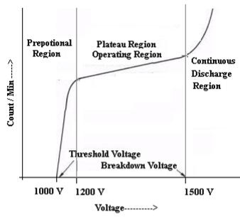
Figure 8: Characteristic curve
QUENCHING
It is the process to prevent the continuous discharge. Self-quenching is done by vapours of ethyl alcohol because its ionization energy is less than the ionization energy of Argon atom.
COUNTING RATE
The G M Counter can count about 5000 particles / sec. The counting rate depends upon the death and recovery time of G M Counter.
DEATH TIME
In the counter, the slowly moving positive argon ion takes 200  sec to reach the cathode. If the second radiation enters the tube during this time, it will not be registered this time is called death time of the counter
RECOVERY TIME
After death time the tube takes another 200  sec to regain the original working condition. This time is called recovery time of the counter.
PARALYSIS TIME
The sum of death and recovery time is known as paralysis time, which is 400  sec. The tube can respond to the second radiation after 400
  sec
sec
TRUE COUNT RATE
If the death time of the counter is τ and the count which is measured by the counter is no then, the true count rate n,
n = n0 / 1-no τ
ADVANTAGES OF GM COUNTER
DISADVANTAGES OF GM COUNTER
Thus, GM Counter is the one which is primarily used due to its advantages. Although it is not free from disadvantages, still its uses make it preferable over other counters.
USE
When radioactive isotopes are used in medical research work on humans, it is important to make sure that the amount of radioactive material administered to human subjects is as little as possible. In order to achieve this, a very sensitive instrument is necessary to measure the radioactivity of materials.
Key Takeaways
The most familiar example of the use of the scintillation mechanism is the TV screen, which emits visible photons under electron bombardment in a cathode-ray tube. It is also one of the oldest techniques used for detecting radiation. In the early years of nuclear physics, Rutherford and his co-workers detected a particles using a micro-scope to view scintillations from a zinc sulphide screen.

Figure 9: Scintillation Detector
The modern scintillation detector followed from the production of materials that are transparent to their own fluorescent light and the development of the photomultiplier tube (PMT) as an extremely sensitive detector of this light. A schematic arrangement for y-ray detection is shown in Figure.
There are several stages in a scintillation detector during which the energy carried by the radiation is transformed before being in the form of a signal suitable for data processing. First, after entering the block of the scintillator, the photon transfers all or part of its energy to an electron or an electron—positron pair. Multiple collisions with other electrons in the material then dissipate the energy into even smaller amounts with the net result that many electrons in the medium are raised to excited states.
Another stage occurs when these excited states lose their energy. In a scintillator, some of the energy transferred to the medium is emitted in the form of a large number of visible or near-visible photons as fluorescent radiation. As many of these photons as possible are directed on to the photosensitive surface (photocathode) of a PMT, which releases photo-electrons. In a PMT, a resistor chain establishes a voltage gradient between the photocathode and a series of electrodes (dynodes) further down the tube to the anode. Electrons from the photocathode are focused and accelerated by the resulting electric field and driven into the surface of the first dynode. Each arriving electron has enough energy to knock out several secondary electrons depending on the voltage applied to the tube. These secondary electrons are accelerated to the next dynode where further from the conduction band to the valence band, the emitted photon is energetic enough to re-excite an electron from the valence band, and the crystal, therefore, is not transparent to its own radiation.
In order to make the crystal into a useful scintillator, a small amount of impurity (activator) is often added — such as thallium to make NaI(TI). These impurity atoms provide states within the energy gap. Now, when energy is deposited in the crystal, a fraction of the excited electrons and holes migrate to the activator sites. Since the energy difference between the activator states is less than the band gap, the energy of photons emitted when these states lose their energy is below that needed to re-excite the main crystal and so the scintillator is transparent to them. The addition of the thallium shifts the wavelength of maximum emission from 333 nm in pure Nal to 410 nm in Nal(T1). The longer wavelength is better matched to the wavelength response of most PMTs.
Properties
Key Takeaways
4.6.1 SEMICONDUCTOR DETECTORS
Semiconductor detectors are widely used where an accurate energy measurement is needed. A detector consists of a single crystal of semiconductor either silicon or germanium, across which a voltage is applied between two attached electrodes.
The device operates like a solid ionization chamber. The transfer of radiation energy to the crystal creates electron-hole (e-h) pair, as in an inorganic scintillator. The electrons in the conduction band are mobile and, under the influence of an applied electric field, move through the crystal at a speed determined by their mobility.
Vacancies or holes in the valence band also move, but in the opposite direction, in a manner analogous to that of a bubble in a liquid, which rises in the opposite direction to the gravitational force acting on the surrounding liquid. The movement of electrons and holes in a semiconductor constitutes a current and if they arrive at their respective electrodes without recombining or becoming trapped at impurity sites in the crystal lattice, the result is a pulse of current proportional to the energy deposited in the crystal.
The average energy to create an e-h pair is about 3.6eV for silicon and 3 eV for germanium. Thus, many more e-h pairs are created per MeV than ion pairs in a gas, for which about 30 eV per ion pair is required.
However, the signal size is still very small and considerable post-amplification is needed. The total time to collect the positive charge in a semiconductor detector is, generally, much shorter than in a typical gas chamber and, therefore, a semiconductor detector can be operated at a higher rate.
The main technological requirement for a semiconductor detector is the extremely high purity (about 1 part in 1012) required in the sensitive region in order to reduce trapping and recombination to a negligible level as the electrons and holes are swept through the material.
In principle, a single crystal of many insulators could be used as a detector, but it is the special techniques developed for semiconductors that enable single crystals to be produced with the required purity from which a detector can be constructed.
Two types of semiconductor detector are in common use. One is called a p—n junction detector and the other an intrinsic detector. The former is usually made of silicon and the latter of germanium.
4.6.2 P-N JUNCTION DETECTOR
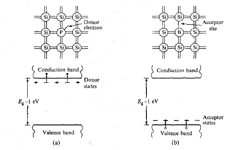
This type of detector is a diode, which is formed at the boundary between two different types of semiconductor. During manufacture, impurity atoms are introduced into the semiconductor material (e.g. boron or phosphorus into silicon), which have a valency one less or one more (3 or 5) than the semiconductor atoms. Phosphorus atoms incorporated into a silicon lattice are 'donor' sites with extra (donor) electrons occupying states which lie close to the conduction band, as shown in Figure 10(a).
These electrons are not strongly bound to these sites and are easily excited into the conduction band where they are mobile. Such material is called n-type because the mobile charge carriers have negative charge. Boron atoms, on the other hand, occupy 'acceptor' sites because they require an extra electron to form a full set of covalent bonds within the crystal. Electrons from the valence band can easily be promoted to these acceptor states, as indicated in Figure 10(b), leaving holes in the valence band, which are also mobile. A hole is effectively a positive-charge carrier and, hence, the material is called p-type. When a junction is made between the two types of semiconductor, electrons from n-type material migrate across the boundary and combine with holes in the p-type material, creating a zone of intrinsically much purer (compensated) material depleted of either weakly bound electrons or trapping sites.
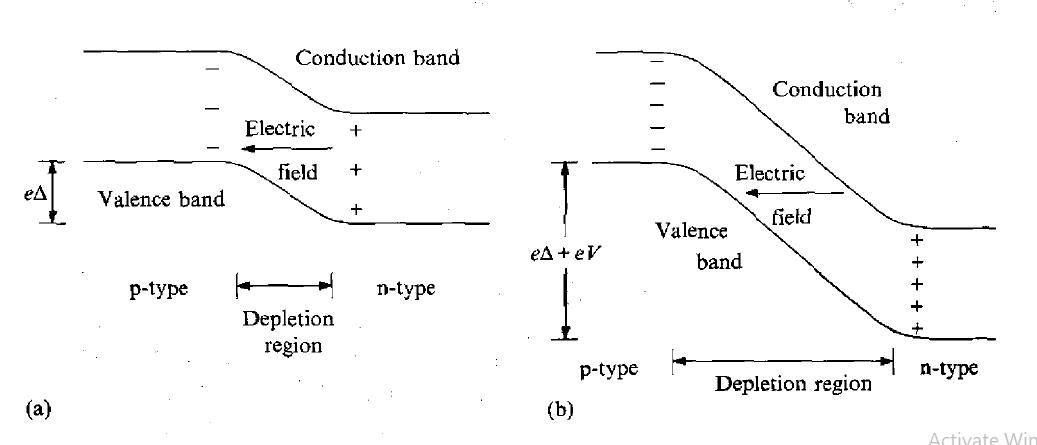
The movement of the charges sets up a voltage (bias) across the junction which eventually stops the net migration. The situation is illustrated in Figure 11(a). The depleted zone is the region of the detector sensitive to radiation. Electrons and holes created by the radiation move under the influence of the electric field across the region and form a current pulse, which is the detected signal. The depleted zone can be made deeper by applying an external voltage V in the reverse bias direction.
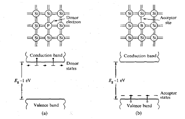
Figure 10: Electronic band structure (a) n-type semiconductor (b) p-type semiconductor
The depth of the zone also depends on the purity of the material. Reverse bias increases the electric field in the depletion zone and, therefore, also increases the rate and efficiency with which electrons and holes are collected at the electrodes.
However, it also gives rise to a small current, known as leakage current, which contributes to electronic noise and a consequent degradation in the signal-to-noise ratio of the output pulse. Much of this leakage can arise from thermal generation of e—h pairs in the semiconductor and is overcome by cooling the material. Thermal excitation is much more likely in germanium than in silicon because of its narrower band gap (0.75 eV) and, for this reason, germanium detectors are usually cooled to near liquid-nitrogen temperature 77 K).
Silicon detectors are normally operated at room temperature unless electronic noise is seriously limiting their performance. Silicon junction-diode detectors are commercially available in a wide range of areas and thicknesses up to several mm. They can also be made very thin (down to about 10 inn) and it is often possible to use several of them stacked together as a detector telescope, which can measure the stopping power of a charged particle passing through the stack, as well as its energy.
Silicon junction diodes are ideal for detecting charged particles and, when cooled, for low-energy photon detection. Their main advantages, relative to gas detectors, are their small size, faster response time and better energy resolution.
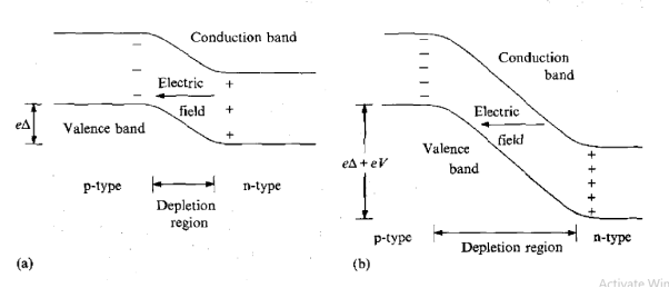
Figure 11: (a) Depletion region in pn junction diode (b) Increased depth of depletion region when reverse biased voltage applied
Multiple detectors can be formed on a single slice of silicon with any desired geometry and they can be made position sensitive. However, all semiconductor detectors suffer from radiation damage since neutrons and other heavy particles can knock atoms from their sites creating imperfections in the crystal lattice where electrons and holes can be trapped. This means that there is a finite, integrated flux of particles of a given type which can be detected before the energy resolution becomes noticeably degraded.
Key Takeaways
4.7.1 BIOLOGICAL EFFECTS OF NUCLEAR RADIATION
We are complex biological organisms constantly exposed to nuclear radiation. When our tissue is exposed, the primary physical interactions are similar to those in any other material, but there are important secondary effects involving chemical reactions.
In addition living tissue actively responds to any damage and has repair mechanisms which have ensured that life has been able to develop and, indeed, thrive in a low-level radiation environment over geological time.
The sequence of events leading to a radiation injury is complex and involves a number of stages during which transformations take place each with its own approximate time scale. Initial interactions occur very quickly (10-12 to 10-8 s) as radiation energy is transferred to the tissue, Some of this causes direct damage to biologically sensitive molecules and some leads to the generation of highly active chemicals which cause additional biomolecular damage in a time scale of 10-7 s to several hours.
Further consequences occur over a period of several days to weeks and, depending on the extent of damage done earlier, may result in the death of cells and even the death of the animal itself. More subtle biological changes, leading to the onset of cancer and the transmission of genetic defects to future generations, may take many years and even centuries to manifest themselves.
The biological effects of radiation have been studied for many decades and are continually being reassessed. A good deal of information about the effects on humans has been obtained from survivors of two nuclear bomb explosions over Japan in 1945 and from major nuclear accidents. As a result, our knowledge of the results of massive human exposure is considerable. Relatively little is known about the more subtle effects of small doses.
4.7.2 DIRECT AND INDIRECT PHYSICAL DAMAGE
The immediate result of the interaction of any radiation with matter is the deposition of energy causing ionization and excitation of atoms and molecules. As we have seen that the extent to which this occurs depends very much on the nature of the radiation and its energy and we review below, for each radiation type, the relevant details pertinent to living tissue.
Heavy charged particles (protons, a particles, heavy ions): These interact directly with the tissue, losing energy according to the Bethe-Bloch formula primarily by colliding with electrons. The density of ionization and excitation generally is high and varies with the square of the charge on the particle for a given speed. It reaches a maximum at the Bragg peak near the end of the range. In tissue, 1-MeV a particles travel only a few tens of micrometres and thus are easily stopped by skin. However, they can cause a great deal of damage if an  -emitting isotope is ingested and more sensitive, internal organs are irradiated.
Electrons: Electrons also lose energy by colliding with electrons but, being light, they are easily scattered and so, unlike heavy charged particles, do not travel in approximately straight lines through matter. Also, their energy loss per unit distance travelled is much smaller than that of 2 particles of the same energy, which means that they are more penetrating. A few millimetres of metal is needed to shield I-MeV  particles. Electrons also lose energy by emitting bremsstrahlung radiation as photons, which may be absorbed elsewhere in the tissue. The net result is that the electron's energy is distributed within a much greater volume and the resulting ionization density is much smaller than that caused by a heavy, charged particle. .
Neutrons: Neutrons do not cause ionization directly. They are uncharged and interact only with other nuclei. Low-energy neutrons (0.025-100 eV) lose energy primarily through the (n, y) capture reaction. Since living tissue has a high density of hydrogen atoms, mostly in the form of water, the main capture process is n + p  d +
d + , releasing a 2.2-MeV photon. At high energies (keV), neutrons lose energy through elastic collisions. Again, because of the high hydrogen content in tissue, elastic scattering by protons predominates. Proton and neutron masses are very similar and, on average, a neutron loses a large fraction of its energy in collision with a proton. The proton recoils, producing a dense trail of ionization as it slows down. Neutrons also collide with other nuclei in tissue, such as carbon and oxygen, which then cause even greater ionization density over a very short range. A 2-MeV neutron travels about 6 cm before being thermalized and thus fast neutrons can deposit regions of high ionization density to a considerable depth in living tissue. At intermediate energies (0.1-20 keV), both scattering and capture are important. However, as the neutrons slow down, rapture predominates because the capture cross section generally varies inversely with the speed of the neutron. In the energy range 0.2-0.025 eV, neutrons can also induce molecular excitation, but the biological damage this may cause is still an open question.
Photons: Photons transfer their energy to electrons via Compton scattering, the photoelectric effect and pair production. The attenuation coefficient for photons depends strongly on energy and the atomic number Z of the material. Tissue contains mainly low Z elements (C, H and 0) and Compton scattering is the most important interaction process for photon energies above about 40 keV to several tens of MeV. The scattered photons may interact further by a second Compton scattering or by photoelectric absorption, depending on the energy. Overall energy deposition in general is not localized. It varies approximately exponentially with depth and can reach deep into tissue. Gamma rays of a few MeV are particularly penetrating and require many centimetres of lead to provide an effective shield.
4.7.3 INDIRECT CHEMICAL DAMAGE
The result of all the physical interaction processes between the tissue and the incident radiation is a trail of ionized and excited atoms and molecules. Some of the radiation energy is transferred by direct interaction on to biologically sensitive material at critical sites and, for highly ionizing particles, this direct action is an important cause of irreversible, biological damage.
However, most of the primary interactions of radiation in tissue result in the ionization of simpler molecules and the creation of chemically active free radicals.
A free radical is an electrically neutral atom or molecule that has an unpaired electron. There is a strong tendency for this electron to pair with a similar one in another radical or to eliminate the odd electron in an electron-transfer reaction. Thus, free radicals are chemically extremely reactive and can be electron acceptors (oxidizers) or donors (reducing agents),
Free radicals are important since they can diffuse far enough to reach and induce chemical changes at critical sites in biological structures. It is this secondary, chemical damage which can dominate the total biological disruption arising from exposure to radiation.
Most direct ionization occurs on water since it comprises about 80% of tissue. For a proper understanding of radiobiological effects, therefore, the radiochemistry of water is of crucial importance. Ionization of a water molecule produces a free electron and a positively charged molecule:

Released electron captured by another water molecule to create negative ion.
As both the ions are unstable so it dissociate as
Creating free radicals OH* and H*
Abstracting hydrogen from organic molecule RH, these free radical create organic free radical R*

The organic free radicals may react with and disrupt other molecules that may be part of a biologically more complex system, such as a chromosome, possibly disabling it and leading to the death of a cell.
Alternatively they may modify the genetic information that is passed on to future generations (a genetic mutation). Evidently, biologically important molecules can be changed both directly by the radiation itself, and indirectly, by the action of secondary free radicals. It is the indirect, chemical damage that accounts for the majority of the changes.
At low radiation levels most of this indirect chemical damage and that caused by relatively weakly ionizing radiation (photons and fi particles) is reparable and does not lead to permanent damage.
Reactions with oxygen in tissue lead to other chemical reactions of biological significance because they produce damaging peroxide radicals (HO2*and hydrogen peroxide (H202). In addition, another set of processes involving organic free radicals is possible in an environment rich in oxygen

These reactions not only fix the molecular change, but result in another free radical which can continue the process in a chain reaction. The increased effectiveness of radiation in the presence of oxygen is known as the oxygen effect.
It has the consequence that irradiated cells have a lower chance of survival in tissue rich in oxygen than in tissue less rich in oxygen. This is unfortunate for the treatment of many tumours, which generally have an inferior blood supply than normal tissue and thus are less well oxygenated.
Key Takeaways
The theories and discoveries of thousands of physicists since the 1930s have resulted in a remarkable insight into the fundamental structure of matter: everything in the universe is found to be made from a few basic building blocks called fundamental particles, governed by four fundamental forces. Our best understanding of how these particles and three of the forces are related to each other is encapsulated in the Standard Model of particle physics. Developed in the early 1970s, it has successfully explained almost all experimental results and precisely predicted a wide variety of phenomena. Over time and through many experiments, the Standard Model has become established as a well-tested physics theory.
As a result of experiments which measure the results of the collision of cosmic rays or accelerated stable particles (such as the electron and proton) with matter, more than 400 "elementary" particles have been discovered. Many of these are unstable, with half-lives ranging from 10^-6 to 10^-23 seconds. The challenge to particle physicists has been to make sense out of this apparently complicated structure of the sub nuclear world. Around 1970, this question was simplified with the discovery that many of the particles (not including electrons or photons) could be considered to be made up of subunits named quarks.
Elementary particles are those microscopic elementary constituents out of which all matter in this universe is made of. Bound neutron is stable but unbound neutron is unstable and it decays according to equation
n → p + e+  (anti-nutrino)
Half-life of free neutron is 14 min 49 sec.
Particle Classification
Elementary particles can be divided into four groups
1. Photons
2. Leptons
π+→ μ++νμ
π–→μ–+ 

μ–→e–+νμ+ ν e ¯
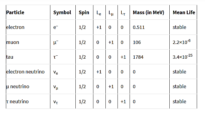
Leptons have (B=0) (fermions) and their properties are

Figure 12: Properties of Leptons
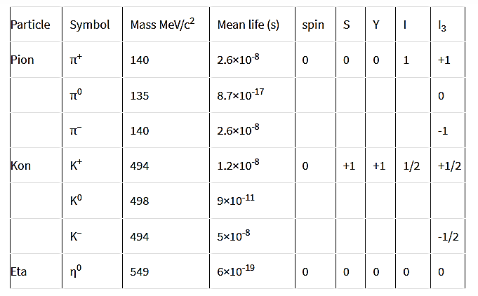
3. Mesons
π-mesons
K mesons
K+→π++π0K+→μ++νμ
K+→π++π++π0
K+→π++π0+π0
K+→e++ν+π0

Figure 13: Properties of Mesons
4. Baryons
Λ0 →p+π–
Σ+→p+π0 ; Σ+→n+π+
Σ–→n+π–
its mass being slightly greater than Σ+ and is 2341 me.
Σ0→Λ0+γ
its mass is 2328me
Ξ–→Λ0+π– and Ξ0→Λ0+π0
Their masses are about 2582 me

Figure 13: Properties of Baryons
Key Takeaways
Fundamental interactions
To understand the properties of elementary particles (by implication, the basis of the entire natural world) we need to describe the forces (or interactions) between them. Four fundamental types of particle interaction have been identified. Matter is effected by forces or interactions (the terms are interchangeable). There are four fundamental forces in the Universe:
The first two you are familiar with, gravity is the attractive force between all matter, electromagnetic force describes the interaction of charged particles and magnetics. Light (photons) is explained by the interaction of electric and magnetic fields.
The strong force binds quarks into protons, neutrons and mesons, and holds the nucleus of the atom together despite the repulsive electromagnetic force between protons. The weak force controls the radioactive decay of atomic nuclei and the reactions between leptons (electrons and neutrinos).
Current physics (called quantum field theory) explains the exchange of energy in interactions by the use of force carriers, called bosons. The long range forces have zero mass force carriers, the graviton and the photon. These operate on scales larger than the solar system. Short range forces have very massive force carriers, the W+, W- and Z for the weak force, the gluon for the strong force. These operate on scales the size of atomic nuclei.
The forces of gravity and electromagnetism are familiar in everyday life. Two new forces are introduced when discussing nuclear phenomena: the strong and weak interactions. When two protons encounter each other, they experience all four of the fundamental forces of nature simultaneously. The weak force governs beta decay and neutrino interactions with nuclei. The strong force, which we generally call the nuclear force, is actually the force that binds quarks together to form baryons (3 quarks) and mesons (a quark and an anti-quark). The nucleons of everyday matter, neutrons and protons, consist of the quark combinations uud and udd, respectively. The symbol u represents a single up quark, while the symbol d represents a single down quark.
The force that holds nucleons together to form an atomic nucleus can be thought to be a residual interaction between quarks inside each individual nucleon. This is analogous to what happens in a molecule. The electrons in an atom are bound to its nucleus by electromagnetism: when two atoms are relatively near, there is a residual interaction between the electron clouds that can form a covalent bond. The nucleus can thus be thought of as a "strong force molecule."
The force between two objects can be described as the exchange of a particle. The exchange particle transfers momentum and energy between the two objects, and is said to mediate the interaction. In each case the interaction is due to the exchange of some particle whose mass determined the range of the interaction. The exchanged particle is said to mediate the interaction.
|
|
Figure 14: Fundamental Forces
Key Takeaways
References:
