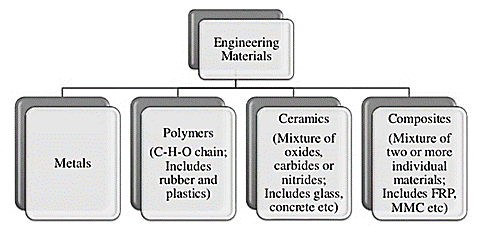
Fig.1 Classification of materials
Mechanical properties of materials:
Classification of steels are as follows: -
Depending upon %C:
These 3 types are further sub-classified as;
Low carbon steels:
Medium carbon steels are also known as machinery steels.
Properties:
Applications: Bolts, axles, springs, wires, wheel spokes, rods, hammers, lock washers, crankpin, turbine rotors, railway rails, railway tyres, cylinder liners etc
High carbon steels:
Properties:
Applications: Knives, Chisels, cutting tools, forging dies, punches, hammers, springs, clips, clutch discs, drills, leaf springs, razer blades, balls and races for ball bearings, mandrels, cutters, reamers etc
Properties:
Properties can be adjusted by suitable alloying elements and heat treatment
This tool contains 3 parts:
1. Center Head
2. Protractor Head
3. Square Head
2. Center Head • Center Head is primarily used for determining the center of round objects but it can also be used to measure 45-degree angle with the rule.
3. Protractor Head • The Protractor head is primarily used to measure exact angles and leveling a surface.
4. Square Head • Square is used to for measuring right angles (90 degree) and 45 degree. This can be used for measuring depths too.
5. Surface Plate • A surface plate is a solid flat plate used as main horizontal reference for precision inspection, like marking out and tooling setup.
6. Angle Plates • This tool is used for marking out and usually supporting tool. This tool is made of cast iron as well.
7. Marking-Out Table • Marking out is a process of transferring a design or pattern to a work and measurement to be taken.
8. V-Blocks • V-Blocks are precision metalworking used to hold round metal rods for performing drilling or milling operation.
9. Spring Dividers • Dividers are tools that used for measuring distances between two point, like arc, radius. • These are classified by their length and legs.
High strength, high hardness and wear resistance, high creep resistance and high oxidation resistance at elevated temperatures.
Contain W, Mo, V and Cr as alloying elements.
High speed steels and super high speed steels belong to this category.
Nickel base alloys:
Inconels, hastealloys, nimonics and waspalloy are some of the alloys belonging to this category Composition of nimonic alloy: 0.2% C, 10% Cr, 20% Co, 5% Mo, 5% Al, 1.3% Ti and rest Ni.
Contain Mo, Cr, Ni and rest Co.
Refractory metals and alloys:
The primary metal castings were created throughout the amount from 4000 to three000 B.C., exploitation stone and metal molds for casting copper. Varied casting processes are developed over time, every with its own characteristics and applications, to fulfill specific style necessities. An outsized form of components and elements are created by casting, cherish engine blocks, crankshafts, automotive elements and powertrains, agricultural and railroad instrumentality, pipes and plumbing fixtures, power-tool housings, gun barrels, cookery pans, jewelry, medical science implants, and extremely massive elements for hydraulic turbines. 2 trends have had a significant impact on the casting trade. The primary is that the mechanization and automation of the casting method, that has LED to vital changes within the use of apparatus and labor. Advanced machinery and automatic process-control systems have replaced ancient ways of casting. The second major trend has been the increasing demand for high-quality castings with shut dimensional tolerances. These classifications are involving mould materials, pattern production, molding processes, and ways of feeding the mold with liquified metal. The key classes are as follows:
Six basic steps in this process:
The pattern is the replica of the device which is the output of the casting process. This when molded in sand forms mold. After filling the mold with the molten metal there is a formation of casting. Patterns play a very important role in casting as they decide the quality as well as perfection in a particular casting process. Gates and runners are the most important components in several types of patterns. The pattern is the basic requirement for the creation of mold and it is always bigger than the size of the casting. There should be a proper selection of patterns so it must be able to sustain rough handling. It forms a mold cavity for casting processes. The patterns may be made of metals like aluminum, brass, plaster, and wax.
2.11.1 Types of Pattern
The various kinds of patterns that we use in casting process are
1. Single piece pattern is the cheapest pattern among all other types of pattern. This pattern generally used in simple processes. It is applied in small scale production. It is often used for the generation of large castings such as stuffing box of steam engine and for creating simple shapes, flat surfaces like simple rectangular blocks. The important characteristic of this pattern is that there is no need of joint in the mold area. In this pattern one surface is considered as flat portion. This flat surface is used for parting plane. Sand tools are used to cut the sand which ultimately make gating system. The molding becomes a difficult task if there is absence of this flat surface. It is expected to lie in cope or drag.
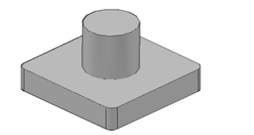
Figure . One Piece Solid Pattern
2. Two- Piece Pattern
Two- piece pattern is also called as split piece pattern. It is the popularly used for intricate castings. The shape of casting decides the exact place of parting plane. This parting plane may be flat or irregular surface. In two- piece pattern half part is always molded in drag and other half part is molded in cope. The cope part of the pattern has dowel pins. These dowel pins are used to align the two halves of split piece pattern. Holes in the drag half of the two- piece pattern matches exactly with dowel pins. It is used in applications where it is very difficult to withdraw casting from the mold. Two- piece patterns are used where the depth of casting is very high.
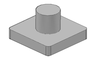
Fig. Two piece pattern
3. Multi Piece Pattern
Sometimes castings have very difficult and complicated designs. In such difficult situations multi piece types of patterns are used. 3 or more patterns are included in multi piece pattern. For instance, if we consider three- piece pattern which comes under multi piece pattern. This three- piece pattern consists of top, bottom and middle parts. The bottom part is drag, top part is cope where the middle part is termed as check box.
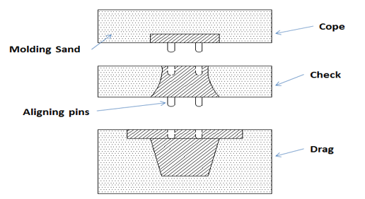
Figure . Multi Piece solid pattern
4. Match Plate Pattern
Basically, Match plate pattern is a split pattern. Cope and drag areas are on the opposite faces of metallic plate. This metallic plate is termed as Match Plate. This type of pattern requires very less hard work and gives very high output. Because the gates and runners are also on the match plate. This is used in various manufacturing industries. This is very expensive and gives accuracy as well as high yield. This pattern is widely used for casting metals like aluminium.
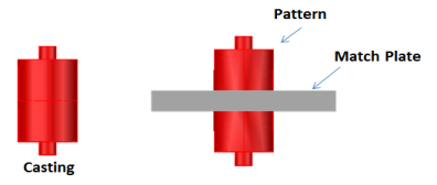
Figure . Match Plate pattern
2.11.2 Pattern Allowance
It is defined as the amount of something that is permitted, especially within a set of regulations or for a specified purpose. While designing pattern, the allowances commonly considered are discussed below.
Shrinkage Allowance:
Generally, metals shrink in size during solidification and cooling in the mould. So, casting becomes smaller than the pattern and the mould cavity.
Therefore, to compensate for this, mould and the pattern should be made larger than the casting by the amount of shrinkage. The amount of compensation for shrinkage is called the shrinkage allowance.
Machining Allowance
In case the casting designed to be machined, they are cast over-sized in those dimensions shown in the finished working drawings. Where machining is done, the machined part is made extra thick which is called machining allowance.
Draft Allowance or Taper Allowance
When a pattern is drawn from a mould, there is always a possibility of damaging the edges of the mould. Draft is taper made on the vertical faces of a pattern to make easier drawing of pattern out of the mould. The draft is expressed in millimeters per meter on a side or in degrees.
Rapping or Shaking Allowance
When the pattern is shaken for easy withdrawal, the mould cavity, hence the casting is slightly increased in size. In order to compensate for this increase, the pattern should be initially made slightly smaller. For small and medium sized castings, this allowance can be ignored. But for large sized and precision castings, however, shaking allowance is to be considered.
Distortion or Chamber Allowance
Sometimes castings, because of their size, shape and type of metal, tend to warp or distort during the cooling period depending on the cooling speed. This is due to the uneven shrinkage of different parts of the casting. Expecting the amount of warpage, a pattern may be made with allowance of warpage. It is called camber. For example, a U-shaped casting will be distorted during cooling with the legs diverging, instead of parallel. For compensating this warpage, the pattern is made with the legs converged but, as the casting cools, the legs straighten and remain parallel Warpage depends on the thickness and method of casting and it is actually determined by experience. Generally, 2 to 3 mm is considered appropriate for 1 meter length.
A riser, also known as a feeder, is a reservoir built into a metal casting mould to prevent cavities due to shrinkage. Most metals are less dense as a liquid than as a solid so castings shrink upon cooling, which can leave a void at the last point to solidify. Risers prevent this by providing molten metal to the casting as it solidifies, so that the cavity forms in the riser and not the casting. Risers are not effective on materials that have a large freezing range, because directional solidification is not possible. They are also not needed for casting processes that utilized pressure to fill the mould cavity. A feeder operated by a treadle is called an under feeder. The activity of planning of how a casting will be gated and risered is called foundry methoding or foundry engineering.
The passageway the metal flows through to get to the gates from the sprue.
Runner Design
One of the most important things to remember in your runners and gates is to avoid sharp corners. Any changes in direction or cross-sectional area should make use of rounded corners. Also make sure the runners and gates are well rammed and smooth. This will help avoid sand erosion and turbulence.
To ensure that the metal is not flowing too fast in the runners the rule of thumb is that the ross sectional area of the runners should be greater than the area of the choke. The walls of the runners should be as smooth as possible to avoid causing turbulence. The runners should be filled with metal before the gates are, one way to ensure this happens is to put the runners in the drag and the gates in the cope. If you need to have a choke in the runner to restrict flow it should be at least 6" from the first gate.
The cross-sectional area of the runners should decrease as the gates come off them to keep the same gating ratio. A good gating ration for aluminum is 1:4:4. The 1 is for the cross-sectional area of the choke. The first 4 is the total cross-sectional area of the runners (measured
after the choke but before the first gate) and the final 4 is total cross-sectional area of the gates.
For example, say you have a tapered sprue with an exit area of 0.5 sq. in., two runners with 2 gates off of each runner. The total runner area should be 2 sq. in so each runner would be 1 sq. in. The total gate area should be 2 sq. in., there are 4 gates so each gate would have an area of 0.5 sq. in. The gate calculation only works this way if there are an equal number of gates on each runner. If that is not the case divide the area of the runner by the number of gates on that runner to get the area of each gate.
The area of the runners should be reduced just after a gate by an amount equal to the area of that gate. This will ensure that each gate in the system will have the same flow of metal, even if it's farther from the sprue. The first bit of metal poured is most likely to be contaminated by air and sand entrapment. To prevent this metal from going into the mold cavity you use a runner extension. That first bit of metal will flow to the end of this dead end and be trapped there, where it can't harm the piece, you're trying to cast. The runner extension will have the same area as that of the last gate on that runner.
Gated Pattern:
They are used in mass production for such castings multi – cavity moulds are prepared i.e.; a single sand mould carries a number of cavities patterns and these castings are connected to each other by means of gate formers. Which provides suitable channels or gates in sand for feeding all the cavities. Gated patterns reduce the moulding time somewhat. Because of their higher cost, these patterns are used for producing small castings in mass production systems and on moulding machines.
Ingredients Of Molding Sands and its composition:
Sand casting is widely used for centuries because of the simplicity of the process. The sand-casting process involves the following basic steps:
(a) place a wooden or metallic pattern in sand to create a mold,
(b) fit in the pattern and sand in a gating system,
(c) remove the pattern,
(d) fill the mold cavity with molten metal,
(e)allow the metal to cool, and
(f) Break the sand mold and remove the casting.
The sand-casting process is usually economical for small batch size production. The quality of the sand casting depends on the quality and uniformity of green sand material that is used for making the mold.

Figure: Construction of sand casting
The major features of molds in sand casting are as follows:
1. The flask, which supports the mold itself. Two-piece molds consist of a cope on top and a drag on the bottom; the seam between them is the parting line. When more than two pieces are used in a sand mold, the additional parts are called cheeks.
2. A pouring basin or pouring cup, into which the molten metal is poured.
3. A sprue, through which the molten metal flows downward.
4. The runner system, which has channels that carry the molten metal from the sprue to the mold cavity. Gates are the inlets into the mold cavity.
5. Risers, which supply additional molten metal to the casting as it shrinks during solidification.
6. Cores, which are inserts made from sand. They are placed in the mold to form hollow regions or otherwise define the interior surface of the casting. Cores also are used on the outside of the casting to form features such as lettering on the surface or deep external pockets.
7. Vents, which are placed in molds to carry off gases produced when the molten metal comes into contact with the sand in the mold and the core. Vents also exhaust air from the mold cavity as the molten metal flows into the mold.
Process of sand casting
The molten metal is poured through the pouring cup and it fills the mold cavity after
passing through down sprue, runner and gate. The core refers to loose pieces which are placed inside the mold cavity to create internal holes or open section.
The riser serves as a reservoir of excess molten metal that facilitates additional filling of mold cavity to compensate for volumetric shrinkage during solidification. Sand castings process provides several advantages. It can be employed for all types of metal.
Advantages:
The tooling cost is low and can be used to cast very complex shapes.
Limitations:
However, sand castings offer poor dimensional accuracy and surface finish.
Applications:
Engine blocks
Sand Casting:
Sand casting is the simplest method of casting aluminum. Sand is made into a mould by forming around a wooden "pattern". The pattern is removed, the sand mould assembled and molten metal poured in. The process is chosen for small production runs, for complex shape castings requiring intricate cores or for very large castings.
Advantages:
Limitations:
Plaster Mould Casting:
Permeable plaster moulds give a smooth surface finish (80~125 rms) with a finer surface detail than is obtainable with shell moulds. Castings as thin as 0.5 mm are possible. Slow solidification rates reduce internal stresses so that any casting distortion is negligible. Machining and finishing operations may be eliminated by the use of plaster moulds. Small holes may be cast to size ready for tapping. Surface finish and dimensional accuracy equates to die casting qualities. LM25 alloys are commonly cast by this process.
Investment Casting:
This casting method involves producing a "wax pattern" by injecting wax or plastic into a pattern die. The pattern is attached to gating and runner systems and this assembly is dipped in a hard setting refractory slurry, which is then cured. The pattern is melted out of the mould to leave an exact cavity. The mould is heated to cure the refractory and to volatilize the remaining wax pattern material. The moulds are baked and molten metal is poured into the mould cavity. On solidification of the casting, the mould material is broken away from the castings.
Shell Moulding:
A shell mould consists of a sand shell, varying in thickness between 4-10 mm. The sand particles are bonded together with phenolic resins giving a permeable mould. The production of shell moulds may be automated which lends itself to medium to high production runs. The resin coated sand is placed on a hot metal pattern; this is fired in an oven to harden the shell. After cooling, the shell is removed from the pattern and is ready for use. Molten metal is then poured into the shell mould cavity and allowed to cool. The mould material is broken off the casting. Better dimensioned tolerances are possible than with sand moulding, which reduces machining costs. Fine surface finishes equal to that of permanent moulds (12~130 rms) may be obtained. and consistently reproducible thin castings with fine detail may be made. The process is more costly than sand, permanent mould or die casting.
Core Sands:
A sand used for making cores is known as core sand. It is silica sand mixed with core oil (linseed oil, resin, mineral oil) and other binding materials (dextrine, corn flour, sodium silicate). It has remarkable compressive strength.
Core making:
Core making is the process which forms the interior part of the casting. The mould provides a space for the molten metal to go, while the core keeps the metal from filling the entire space.
Cores are produced by blowing, ramming or in heated processes, investing sand into a core box. The finished cores, which can be solid or hollow, are inserted into the mould to provide the internal cavities of the casting before the mould halves are joined. Sand cores are also widely used in die-casting, where permanent metal moulds are employed.
A core assembly for an injection molding-machine. The assembly includes a movable mold half and a stationary mold half clamped onto each their platen of an injection molding-machine. It also includes an actuator for advancing and retracting during operation at least one core into and from a mold cavity in a mold. The actuator is connected to a core-carrier for carrying the at least one core. The core-carrier is slidingly mounted to and partly projecting from a guidance connected to one of the mold halves. A first hole is formed in the closed mold for slidingly receiving the projecting part of the core-carrier. The core assembly allows products to be continuously molded with an extremely high degree of accuracy, and it is simple, inexpensive and easy to mount and maintain while also allowing for positioning of cores at various angles relative to the mold.
Mold assembly is one of the most critical steps of mold making procedure, all the parts machined or purchased need to be put together and required to be work functionality. Mold assembly job requires comprehensive understanding of mold structure as well as injection molding. Quality of mold assembly determines the mold precision, injection productivity. The work instructions below can be treated as a guide for mold makers.
All parts are machined correct and clean, the work tools required are available and the workplace is well organized, before assembling the mold, all the components must be check and verified.
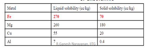
The solubility of hydrogen in various metals are shown in figure. Here solubility S is the volume of H2 gas absorbed by 100 g. of metal. The solubility of hydrogen in solid and liquid phases (pressure = 1 atm) at solidus temperature is given in table.
S = C exp [ _Es / (k
Es – heat of solution of one mol of hydrogen; sign determines endothermic or exothermic
Pouring:
Once heating, the metal is prepared for gushing. Introduction of liquefied metal into the mould, as well as its flow through the gating system and into the cavity could be an essential step within the casting method. For this step to achieve success, the metal should flow into all regions of the mould before curing. Factors moving the gushing operation embody pouring temperature, gushing rate, and turbulence. The gushing temperature is that the temperature of the liquefied metal because it is introduced into the mould. What’s vital here is that the distinction between the temperature at gushing and also the temperature at that temperature reduction begins (the freezing point for a pure metal or the liquidus temperature for alloy). This temperature distinction is usually observed because the superheat. This term is additionally used for the number of warmth that has to be off from the liquefied metal between gushing and once curing commences.
Gushing rate refers to the meter rate at that the liquified metal is poured into the mould. If the speed is simply too slow, the metal can chill and freeze before filling the cavity. If the gushing rate is excessive, turbulence will become a significant drawback. Turbulence in fluid flow is characterized by erratic variations within the magnitude and direction of the rate throughout the fluid. The flow is agitated and irregular instead of swish and efficient, as in streamline flow. flow ought to be avoided throughout gushing for many reasons. It tends to accelerate the formation of metal oxides which will become entrapped throughout curing, so degrading the standard of the casting. Turbulence conjointly aggravates mould erosion, the gradual eroding of the mould surfaces because of impact of the flowing liquefied metal. The densities of most liquefied metals are a lot of above water and alternative fluids we have a tendency to usually affect. These liquefied metals also are rather more with chemicals reactive than at temperature. Consequently, the damage caused by the flow of those metals within the mould is important, particularly beneath turbulent conditions. Erosion is very serious once it happens within the main cavity as a result of the pure mathematics of the forged part is affected.
Engineering Analysis of Pouring:
There are many relationships that govern the flow of liquid metal through the gating system and into the mould. A very important relationship is Bernoulli’s theorem that states that the additions of the energies (head, pressure, kinetic, and friction) at any 2 points in a very flowing liquid are equal. This will be written within the following form:

where h = head, cm (in); p = pressure on the liquid, N=cm2(lb/ in2);  = density, g/cm3 (lbm/in3); v = flow velocity; cm/s (in/sec); g = gravitational acceleration constant,981 cm/s/s (32.2×12 = 386 in/sec/sec); and F = head losses due to friction, cm (in). Subscripts1 and 2 indicate any two locations in the liquid flow.
Bernoulli’s equation is simplified in many ways that. If we have a tendency to ignore friction losses (to take care, friction can have an effect on the liquid flow through a sand mold), and assume that the system remains at gas pressure throughout, then the equation is reduced to

This can be accustomed confirm the rate of the liquefied metal at the bottom of the tropical sprue. Allow us to outline purpose one at the highest of the tropical sprue and point two at its base. If purpose two is employed because the reference plane, then the pinnacle at that time is zero (h2 = 0) and h1 is that the height (length) of the tropical sprue. Once the metal is poured into the gushing cup and overflows down the tropical sprue, its initial speed at the highest is zero (v1 = 0). Hence, Eq. more simplifies to

which is resolved for the flow velocity:

where v = the velocity of the liquid metal at the base of the sprue, cm/s (in/sec);
g = 981 cm/s/s (386 in/sec/sec); and h = the height of the sprue, cm (in).
Another relationship of importance throughout gushing is that the continuity law, that states that the quantity rate of flow remains constant throughout the liquid. the quantity flow is up to the rate increased by the cross-sectional space of the flowing liquid. The continuity law is expressed:

where Q = volumetric flow rate, cm3/s (in3/sec); v =velocity as before;
A = cross-sectional area of the liquid, cm2 (in2); and also, the subscripts check with any 2 points within the flow system. Thus, a rise in space leads to a decrease in speed, and contrariwise.
Above equations indicate that the tropical sprue ought to be tapered. Because the metal accelerates throughout its descent into the tropical sprue gap, the cross-sectional space of the channel should be reduced; otherwise, because the speed of the flowing metal will increase toward the bottom of the tropical sprue, air is aspirated into the liquid and conducted into the mould cavity. to forestall this condition, the tropical sprue is meant with a taper, in order that the quantity flow vA is that the same at the highest and bottom of the tropical sprue. Presumptuous that the runner from the tropical sprue base to the mould cavity is horizontal (and thus the pinnacle h is that the same as at the sprue base), then the quantity rate of flow through the gate and into the mould cavity remains up to vA at the bottom. Consequently, we are able to estimate the time needed to fill a mould cavity of volume V as

Where TMF = mold filling time, s (sec); V = volume of mold cavity, cm3 (in3); and Q = volume flow rate, as before. The mold filling time computed by Eq. must be considered a minimum time. this is often as a result of the analysis ignores friction losses and potential constriction of flow within the gating system; so, the mould filling time are going to be longer than what's given by above Eq.
In context with the casting process, fettling means the removal of unwanted metal, e.g., flashings, risers etc.
It can include processes like chipping, grinding, shot blasting etc.
It involves the removal of the cores, gates, sprues, runners, risers and chipping of any of unnecessary projections on the surface of the castings.
Fettling operations can be divided into different stages:
Varied defects will develop throughout producing that rely on factors cherish materials, half style, and process techniques. Whereas some defects have an effect on solely the looks of the components created, others will have major adverse effects on the structural integrity of the components. Many defects will develop in castings. As a result of totally different names are utilized in the past to explain an equivalent defect, the International Committee of metalworks Technical Associations has developed an identical word consisting of seven basic classes of casting defects, known with boldface capital letters:
A-Metallic projections, consisting of fins, flash, or projections cherish swells and rough surfaces.
B-Cavities, consisting of rounded or rough internal or exposed cavities as well as blowholes, pinholes, and shrinkage cavities.
C-Discontinuities cherish cracks, cold or hot tearing, and cold shuts. If the curing metal is unnatural from shrinking freely, cracking and tearing might occur. Though many factors are concerned in tearing, coarse grain size and also the presence of low-melting-point segregates on the grain boundaries (inter granular) increase the tendency for warm tearing. Cold shut is interface in a very casting that lacks complete fusion as a result of the meeting of 2 streams of liquid metal from totally different gates.
D-Defective surface, cherish surface folds, laps, scars, adhering sand layers, and compound scale.
E-Incomplete casting, cherish misruns (due to premature solidification), lean volume of the metal poured, and run out (due to loss of metal from the mould once pouring). Incomplete castings can also result from the liquefied metal being at too low a temperature or from pouring the metal too slowly.
F-Incorrect dimensions or shape, because of factors cherish improper shrinkage allowance, pattern-mounting error, irregular contraction, malformed pattern, or crooked casting.
G-Inclusions, that type throughout melting, solidification, and molding; these are typically nonmetal. They’re considered harmful as a result of they act as stress raisers and so cut back the strength of the casting. Inclusions might type throughout melting once the liquefied metal reacts with the atmosphere (usually oxygen) or with the vessel or mould material. Chemical reactions among elements within the liquefied metal itself might manufacture inclusions; slags and alternative foreign material entrapped in the molten metal conjointly become inclusions, though filtering will take away particles as little as thirty um. Finally, spilling of the mould and core surfaces will manufacture inclusions, so indicating the importance of the standard of molds and of their maintenance.
Residual Stresses:
“Internal” or “residual”, regardless of however we have a tendency to outline them, in a very metal material such stresses continually derive from some irregularity conditions within the fabric, irregularity that in castings is mostly including the very fact that the casting cooling doesn't occur at the same time altogether points, since the inner surface cools quicker than the fabric core, and also the zones with refined walls before the massive components. Generally terms “the residual stresses are generated within the part once irregularity components are gift within the science or material method characteristics”. within the case of castings, aside from gross errors resulting in have homogeneity variations of the fabric among the varied zones of the half, the most supply of residual stresses is beyond any doubt the cooling method or, better, the non-simultaneous cooling among the varied zones of an equivalent part. Reminding of course that the particular volume of a metal material is directly proportional to temperature, it results that once the cooling of the external casting half happens, and internal half is implanted by high-temperature material.
Once the cooling extends to the fabric core, too, this may not shrink freely as a result of unnatural by the external solid surface: thus, we are going to have the external half stressed by compression by the core material, that in its flip are going to be stressed by traction by the external half. Analogue concerns are valid if the casting options components with totally different thickness, with components with refined stable walls before the parts with larger section, so the establishing of mutual traction or perhaps of deformations. we are able to thus state that the strain state in a very casting with refined walls has a minimum of 2 elements, one that we have a tendency to might outline “vertical” elicited by the interactions between the fabric on the surface and also the underlying material, and a “geometrical” one elicited by the constraints implanted by the encompassing material.
PRESSURE TESTING:
DESTRUCTIVE TESTING:
NON-DESTRUCTIVE TESTING:
Here parts to be tested are inspected for internal.
Here parts to be tested are inspected for internal defects and surface defects without destroying the defects and surface defects without destroying the component.
Various methods available are:
Reference Books: