Unit 3
Cold Working
1. Shearing
It is a cut in a straight line across a strip, sheet or bar. It leaves a lean edge on the piece of metal is sheared or cut. In this operation, a sheet metal workpiece is placed or kept between two dies from one end. And, the punch is hit at the other end of the sheet, producing a shearing effect.
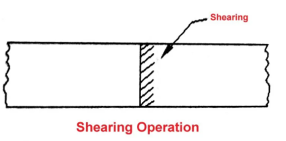
Figure 1. Shearing
It has 3 basic stages:
a) Plastic Deformation
When a metal is placed between the upper and lower blades of the shear and pressure is applied, plastic deformation takes place. It extends into metal for about 5 to 40% of metal thickness.
b) Fracture
At the point of greatest stress concentration fracture takes place.
c) Shear
Small fractures are found and the metal is sheared.
2. Blanking
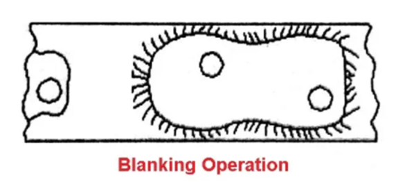
Figure 2. Blanking
It is an operation of cutting a whole piece from sheet metal. In which enough scrap is left all around as shown in fig. A punch and die is applied for this type of sheet metal operation.
3. Punching
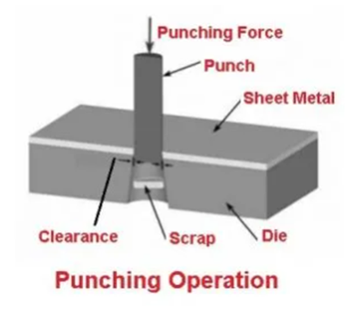
Figure 3. Punching
It is an operation of producing circular holes on a sheet of metal by a punch and die. This is the exact opposite of blanking but the operation is nearly the same. A Punch and die are further used here such as blanking operations.
4. Piercing
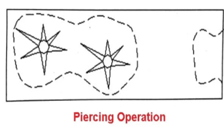
Figure 4. Piercing
Piercing is the process in which desired shape holes are produced in a piece of sheet metal without eliminating any material from the sheet or removing a very small amount of material as shown in the figure. Both punch and die are also applied in this operation. The punch used in the piercing operation is usually bullet-shaped.
5. Trimming
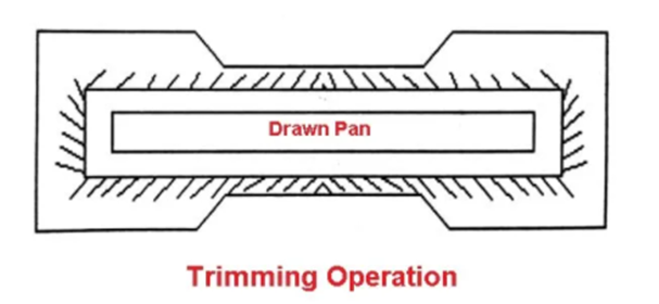
Figure 5. Trimming
The trimming operation is also known as shaving operation. It is a finishing operation by removing the burrs from the cut edges is taken out in order to make edges smooth and also provide dimensional accuracy.
6. Drawing
It is an operation of producing thin-walled hallows or vessel shaped parts from sheet metal. It can be divided into two categories:
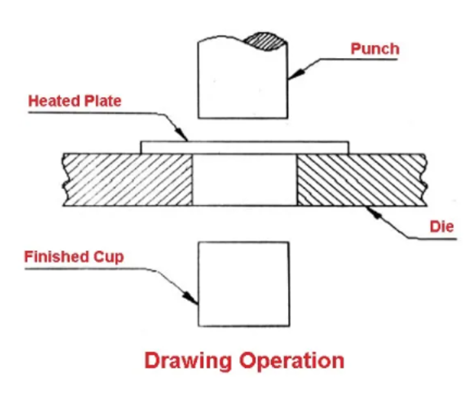
Figure 6. Drawing
a) Deep Drawing
The length of depth of the object to be drawn is deeper than its width.
b) Shallow Drawing
The length of the object to be drawn is less than its width. The examples of drawing are pans, tubes and cams.
7. Embossing
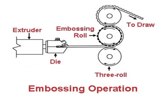
Figure 7. Embossing
It is the metalworking operation which is used to create raised surfaces or lettering in sheet metal. There is no change in metal thickness during this operation.
8. Bending
It occurs when forces are applied to localized areas. Here the metal flow is uniform along the bend axis with the inner surface in compression and outer surface in tension.
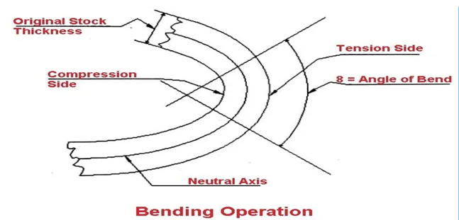
Figure 8. Bending
9. Squeezing
It is a quick and widely used way of forming ductile metals. It has different operations such as sizing, coining, riveting etc.
1. Sizing
Sizing operation is a squeezing operation that reduces the thickness of the metal. The sizing is done in an open die and only the surface where the die and workpiece touch will be sized.
2. Coining
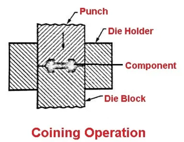
Figure 9. Coining
It is a process of pressing metal in a die so that it flows into the die space. For example, Medals, Coins, and Jewellery.
Measuring instruments:
2. MEASURING TAPE:
3. VERNIER CALLIPERS:
4. SCREW GAUGE:
1. Shearing
It is a cut in a straight line across a strip, sheet or bar. It leaves a lean edge on the piece of metal is sheared or cut. In this operation, a sheet metal workpiece is placed or kept between two dies from one end. And, the punch is hit at the other end of the sheet, producing a shearing effect.
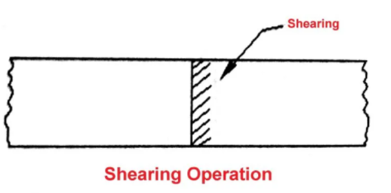
Figure 10 . Shearing Operation
It has 3 basic stages:
a) Plastic Deformation
When a metal is placed between the upper and lower blades of the shear and pressure is applied, plastic deformation takes place. It extends into metal for about 5 to 40% of metal thickness.
b) Fracture
At the point of greatest stress concentration fracture takes place.
c) Shear
Small fractures are found and the metal is sheared.
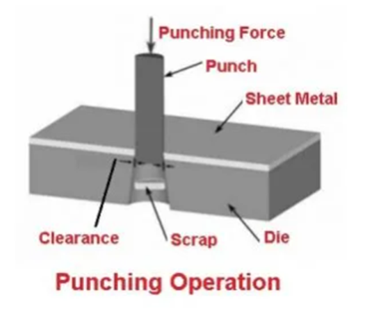
Figure 11. Punching Operation
It is an operation of producing circular holes on a sheet of metal by a punch and die. This is the exact opposite of blanking but the operation is nearly the same. A Punch and die are further used here such as blanking operations.
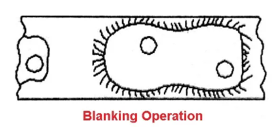
Figure 12. Blanking Operation
It is an operation of cutting a whole piece from sheet metal. In which enough scrap is left all around as shown in fig. A punch and die is applied for this type of sheet metal operation.
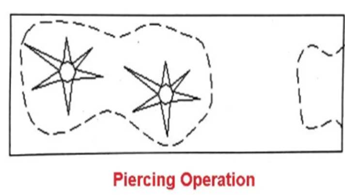
Figure 13. Piercing Operation
Piercing is the process in which desired shape holes are produced in a piece of sheet metal without eliminating any material from the sheet or removing a very small amount of material as shown in the figure. Both punch and die are also applied in this operation. The punch used in the piercing operation is usually bullet-shaped.
Forming is a process in which the desired size and shape are obtained through the plastic deformation of a material. The stresses induced during the process are greater than the yield strength, but less than the fracture strength of the material. The types of loading may be tensile, compressive, bending, or shearing, or a combination of these.
This is a very economical process as the desired shape, size, and finish can be obtained without any significant loss of material. Moreover, a part of the input energy is fruitfully utilized in improving the strength of the product. The typical forming processes are (i) rolling, (ii) forging, (iii) drawing, (iv) deep drawing, (v) bending, and (vi) extrusion.
Bending:
It occurs when forces are applied to localized areas. Here the metal flow is uniform along the bend axis with the inner surface in compression and outer surface in tension.
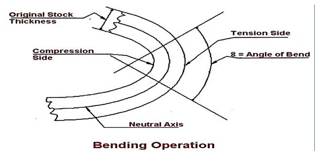
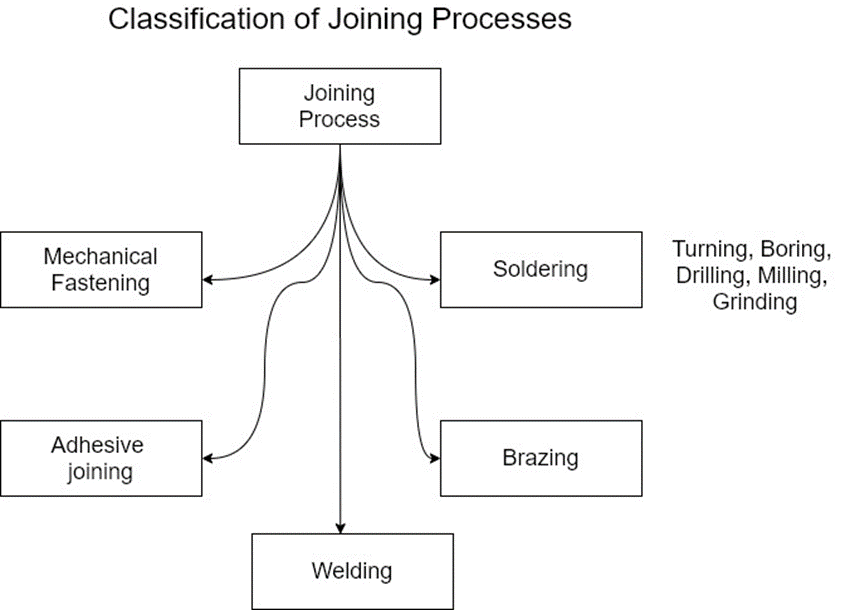
Figure 14. Bending and Joining process
The process of joining two similar or dissimilar materials is referred as joining process. The joining process is referred as joining process, when there is the use of fasteners to joint them.
The term ‘joining’ is mainly used for welding, brazing, soldering, and adhesive bonding that form a permanent or a temporary joint between the parts. Permanent joint is referred to a joint that cannot easily be separated while temporary joint is the joint that can be easily separated when required.
The joining process can be divided into a liquid state joining or a solid-state joining process.
These processes are primarily used for the assembly of the machine to join various parts either permanently or temporarily.
Joining process generally contains the processes like welding, brazing, soldering, joining, adhesive bonding, etc.
Welding process is the most widely used process for a permanent joint. While joining process is most widely used process for temporary joint.
Joining process can be divided into three types:

b. Semi-permanent fastening process: It includes snap fit, Blind rivet, press fit, etc.
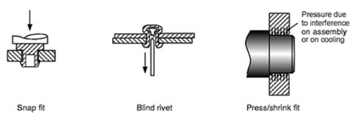
c. Non-permanent fastening process: When the joint required is temporary, then non-permanent fastening process is used. It includes Retaining, self-tapping, nut-bolt assembly, etc.

Figure 15. Joining Fastening Process
3.10.1 Advantages
1. The amount of wastage of metal during metal forming process is negligible.
2. Grain orientation is possible.
3. Because of grain orientation the material is converted from isotropic to anisotropic material.
4. Sometimes the strength and hardness of work material i s increasing.
5. Some other metal forming process, the surface finish obtained on the component is very good and excellent.
3.10.2 Limitations
If the metalworking process is carried out above its re-crystallization temperature, it is called hot working.
Re-crystallization temperature is the temperature at which atomic mobility can be repaired when any defect was present in the metal caused by the working process. In this process, the metal is heated to the plastic state, and then the pressure is applied to get various sizes and shapes. When the pressure is applied, the metal grain size will be varied, and the metal’s mechanical properties are improved.
3.11.2 Principles
If the pressure is applied by a hand hammer, then it is called hand or smith forging. If hand hammering is replaced by power hammers, then it is called hammer forging. Such a type of hot working of metals is called hot forging. Hot-working can be used for forging, extrusion, and drawing, etc.
When metals are worked above the re-crystallization temperature, then it becomes plastic and causes the growth of grains. During the hot working, the grains become loosened in their structure, and they realign properly. Only small pressure is required to shape the metal.
Rolling: In this process, the workpiece in the form of slab or plate is compressed between two rotating rolls in the thickness direction, so that the thickness is reduced. The rotating rolls draw the slab into the gap and compresses it. The final product is in the form of sheet.
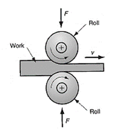
Fig16. Rolling
Extrusion: In this, the workpiece is compressed or pushed into the die opening to take the shape of the die hole as its cross section.
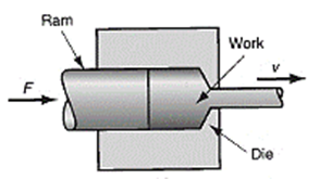
Fig17. Extrusion
Drawing is an operation in which the cross-section of solid rod, wire or tubing is reduced or changed in shape by pulling it through a die. The principle of this procedure consists of reducing the thickness of a pointed, tapered wire by drawing it through a conical opening in a tool made of a hard material. The wire will take shape of the hole. Drawing improves strength and hardness when these properties are to be developed by cold work and not by subsequent heat treatment.
This process is widely used for the production of thicker walled seamless tubes and cylinders therefore; shafts, spindles, and small pistons and as the raw material for fasteners such as rivets, bolts, screws. Drawing is classified as
1. Wire drawing
2. Tube drawing
Wire Drawing:-
Wire drawing is a metal-reducing process in which a wire rod is pulled or drawn through a single die or a series of continuous dies, thereby reducing its diameter. Because the volume of the wire remains the same, the length of the wire changes according to its new diameter. Various wire tempers can be produced by a series of drawing and annealing operations. (Temper refers to toughness.) (a)
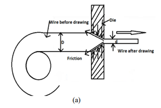
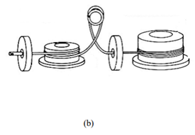
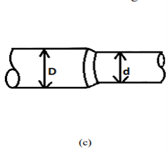
Figure18-(a)Wire Drawing sectional view (b) wire drawing set up (c) Enlarge View of Wire Reduction
Process Characteristics
Tube Drawing
When a hollow tube is drawn through a die, generally a mandrel or plug is used to support the inside diameter of the tube, this process is called tube drawing. The function of the plug is to effect wall reduction and to control the size of the hole. However, the mandrel may be omitted if it is not necessary to make a reduction in the wall thickness, or if the dimensions and surface of the inside are not important. The process to draw a pipe without any mandrel is known as tube sinking.
In drawing tubes over a stationary mandrel, the maximum practical sectional area reduction does not exceed 40 per cent per pass due to the increased friction from the mandrel. If a carefully matched mandrel floats in the throat of the die, it is possible to achieve a reduction in area of 45 percent, and for the same reduction the drawing loads are lower than for drawing with a fixed plug. This style is called the drawing with floating plug. It is worth mentioning here that in this style, the tool design and lubrication can be very critical. Problems with friction in tube drawing are minimized in drawing with a long mandrel. The mandrel consists of a long hard rod or wire that extends over the entire length of the tube and is drawn through the die with the tube.
In this design, the area reduction can be 50 per cent. However, after drawing, the mandrel must be removed from the tube by rolling (reeling), which increases the tube diameter slightly and disturbs the dimensional tolerances. The drawing process discussed above has been illustrated in the figure
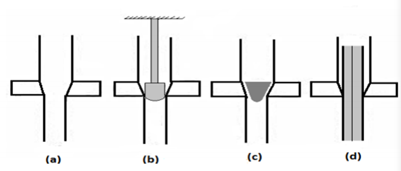
Figure 19-Tube drawing processes. (a) Sinking; (b) fixed plug; (c) floating plug; (d) moving mandrel
Defects in drawing process:

Figure 20 (a) Wrinkling in the flange or (b) in the wall (c) tearing, (d) Earing, (e) surface scratches
Eg: Lathe , Shaper, Planer , Milling, Drilling
Machine tools are defined as machines used for carrying out the metal cutting processes and surface finish processes by removing the material from the work piece in the form of chips.
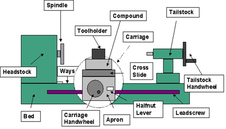
Figure 21. Lathe
A lathe is one of the oldest & most important machine tools ever developed. The job to be machined is rotated & the cutting tool is moved relative to the job. That is why, It’s also called as “ Turning Machine”.A Lathe was basically developed to machine cylindrical surfaces. But many other operations can also be performed on lathes. e.g.-facing, parting, necking, knurling, taper turning & forming. We also can perform operations of other machine tools on a lathe, e.g. drilling, reaming, milling & drilling operation etc.A lathe is called the mother of the entire machine tool family.The lathe can be defined as a machine tool which holds the work between two rigid & strong centres, or in a chuck or face plate while the latter revolves. The cutting tool is rigidly held & supported in a tool post & feed against the revolving work.
Planer and shaper:
Planning and shaping are similar operations, which differ only in the kinematics of the process. Planning is a machining operation in which the primary cutting motion is performed by the workpiece and feed motion is imparted to the cutting tool. In shaping, the primary motion is performed by the tool, and feed by the workpiece.
Milling
Milling is a process of producing flat and complex shapes with the use of multi-point (or multi-tooth) cutting tool. The axis of rotation of the cutting tool is perpendicular to the direction of feed, either parallel or perpendicular to the machined surface. Milling is usually an interrupted cutting operation
since the teeth of the milling cutter enter and exit the workpiece during each revolution.
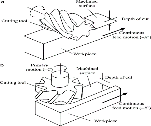
Figure 22. Milling
Drilling
Drilling is a process of producing round holes in a solid material or enlarging existing holes with the use of multi-point cutting tools called drills or drill bits. Various cutting tools are available for drilling, but the most common is the twist drill.
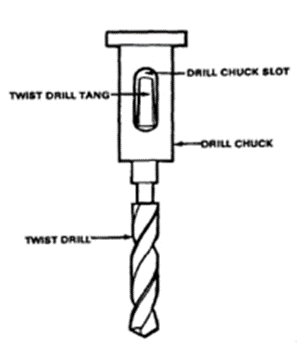

Figure 23: A cross-sectional view of the machining process; Tool with negative rake angle
1.2 Types of Cutting Tool
(a) Single-point tools and (b) Multiple-cutting-edge tools.

Figure 24: (a) A single-point tool showing rake face, flank, and tool point; and (b) a helical milling cutter, representative of tools with multiple cutting edges.
(i) Side cutting edge: The top edge of the major flank
(ii) End cutting edge: The top edge of the minor flank
The angles of a single point cutting tool have great importance. Each angle has its own function and specialty.
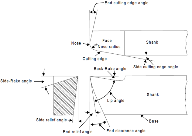
Figure 25: Tool Geometry of a single point cutting tool
Tool wear:
Tool subjected to:
1. Forces
2. Temperature
3. Sliding action
After continuous use for some time, tool gives unsatisfactory or inefficient performance.
Unsatisfactory or inefficient performance is due to “Tool Wear or Tool failure”. Consequences:
1. Loss of dimensional accuracy
2. Increased surface roughness
3. Increased power requirement
4. Excessive vibration and abnormal sound (Chatter)
5. Total breakage of the tool
Tool is replaced or reconditioned usually by grinding.
Tool Wear depending factors:
1. Type of tool material and its hardness
2. Type and condition of work piece material
3. Dimensions of cut (Feed and depth of cut)
4. Cutting speed
5. Tool geometry
6. Tool temperature (function of cutting speed, feed and depth of cut)
7. Type of cutting fluid
Classification of Tool Wear
1. Flank wear
2. Crater wear on tool face
3. Localized wear such as the rounding of Cutting edge
4. Chipping of the cutting edge
Mechanics of Chip Formation:
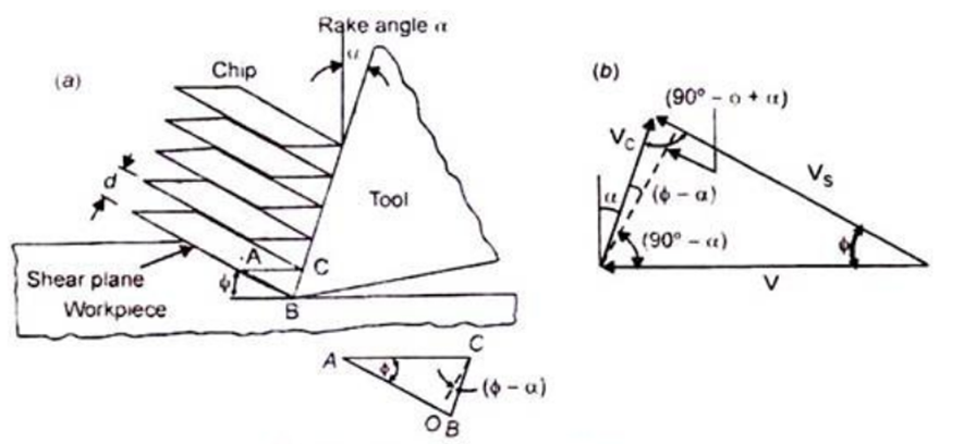
Figure 26: Mechanics of chip formation

Shear Plane
Shear Plane Angle
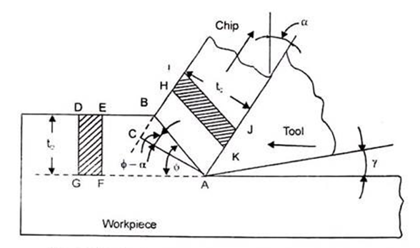
Figure 27: Mechanism of chip formation in orthogonal cutting
Derivation to Calculate Shear Angles:
(i) Tool should contacts the chip on its rake face.
(ii) Plain strain conditions considered. It means there is no side flow of the chip during cutting.
(iii) The deformation zone is very thin (in the order of 10-2 to 10-3 mm) adjacent to the shear plane AB.
In the figure 1.7 following symbols was used:
α – Rake angle
γ – Clearance (relief) angle
φ – Shear angle
AB – Shear plane
t0 – Uncut chip thickness
tc – Chip thickness (deformed)
Area DEFG – Area of uncut chip
Area HIJK – Chip area after cutting.
From the above figure,


The chip thickness ratio can be expressed as

The chip reduction ratio becomes


This is the required relation to calculate the shear angle (φ). This relation shows that φ depends upon the t0, tc, and α (rake angle). It means by measuring t0, tc and α of the tool, shear angle (φ) can be determined using above expression.
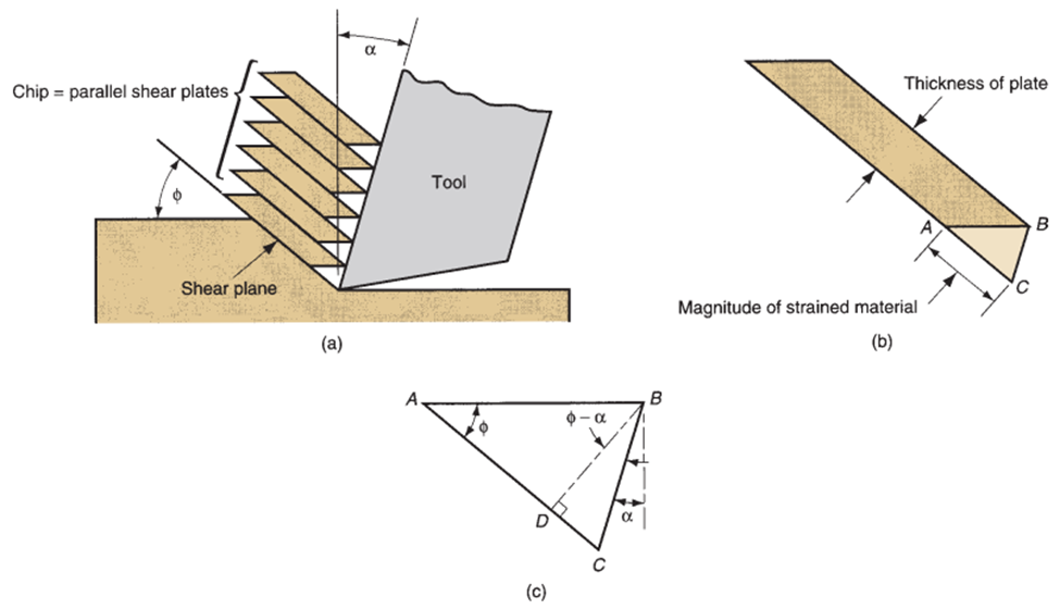
Figure 28: Shear strain during chip formation: (a) chip formation depicted as a series of parallel plates sliding relative to each other; (b) one of the plates isolated to illustrate the definition of shear strain based on this parallel plate model; and (c) shear strain triangle

It can be reduced to the following definition of shear strain in metal cutting process

Velocities in Metal Cutting Process:
(i) Cutting Speed or Velocity (V):
Cutting velocity is the velocity of the cutting tool relative to the work piece.
(ii) Shear Velocity (Vs):
Shear velocity is the velocity of chip relative to the work piece. This is the velocity at which shearing takes place.
(iii) Chip Velocity (Vc):
Chip velocity is the velocity of the chip, up the tool face (rake face) during cutting.
Let, V – Cutting Velocity
Vs – Shear Velocity
Vc – Chip velocity
φ – Shear angle
α – Rake angle
r – Chip thickness ratio
γ – Clearance angle
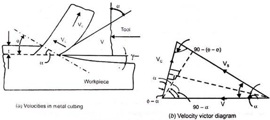
Figure 29: Velocities in Metal Cutting Process
Using continuity equation, the volume of metal removal before and after is same:
V.t = Vc. tc
Vc / V = t / tc = r
Using sine rule to the velocity vectors we can write:


Similarly, 
Also, 
From kinematics theory, the relative velocity of the two bodies (tool and chip) is equal to the vector difference between their velocities relative to the reference body (work piece).
V = VC + VS
Four Basic Types of Chip in Machining:
1. Discontinuous chip
2. Continuous chip
3. Continuous chip with Built-up Edge (BUE)
4. Serrated chip
Continuous chips usually form under the following conditions:
CCs may, because of friction, develop a secondary shear zone at tool–chip interface. The secondary zone becomes thicker as tool–chip friction increases. In CCs, deformation may also take place along a wide primary shear zone with curved boundaries.
2. Discontinuous chips:
1. Brittle work piece materials
2. Work piece materials that contain hard inclusions and impurities, or have structures such as the graphite flakes in gray cast iron.
3. Very low or very high cutting speeds.
4. Large depths of cut.
5. Low rake angles.
6. Lack of an effective cutting fluid.
7. Low stiffness of the machine tool.
Because of the discontinuous nature of chip formation, forces continually vary during cutting. Hence, the stiffness or rigidity of the cutting-tool holder, the Work holding devices, and the machine tool are important in cutting with both DC and serrated-chip formation.
3. Built-Up Edges Chips:
4. Serrated chips:
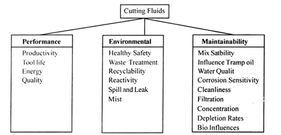
Functions of Cutting Fluids:
The main functions of cutting fluids used in machining process are:
1. For Heat Dissipation:
To dissipate the heat generated during machining cutting fluids are used.
2. To Cool the Workpiece:
To cool the workpiece by carrying away the heat by coolant.
3. To Cool the Tool:
To cool the cutting tool by cooling down the cutting zone.
4. To Reduce Friction and Wear:
To reduce the friction and wear of the tool with the help of lubricants.
5. To Reduce Forces and Energy Consumption:
It decreases the power consumption in cutting the material, by reducing wear.
6. To Improve the Tool Life:
By dissipating the heat generated properly.
7. To Improve the Surface Finish:
By carrying away the heat from work material.
8. To Flush Away the Chips:
To keep the cutting zone free from hot chips and to cause chips to breakup into small parts.
9. To Protect Machined Surface from Environmental Corrosion:
Corrosion inhibitors like triethanolamine or sodium nitrate is added in the cutting fluids to prevent corrosion of the machined surface.
Desirable Properties of Cutting Fluid:
1. Lubricating Qualities:
This quality reduces frictional force between the workpiece and the tool. It also prevents the formation of built-up edge on the workpiece.
2. High Heat Carrying (Cooling) Capacity:
Cutting fluid must carry maximum heat from cutting zone quickly. Thus, reducing the temperature of the workpiece and the tool. This will reduce tool wear, increase tool life and surface finish of the work.
A small reduction in temperature can considerably increase the tool life, according to the following empirical relation:
Tθn = K
Where, T= Tool life (min)
θ = Temperature at the chip tool interface (°C)
n = An exponent that depends on tool form and material
K = Constant
3. Corrosion Resistant:
The cutting fluid must prevent the work material from environmental rusting or corrosion. For this purpose corrosion inhibitor like sodium nitrate along with other additives is added in cutting fluid.
4. Low Viscosity:
It must have low viscosity; so that chip and dirt can settle quickly.
5. Stability:
It must have long life; it should not get spoiled quickly, both in use and in storage.
6. Non-Toxic:
It must be non-toxic and should not be injurious to the human skin.
7. Non-Flammable:
It must have high flash point, and should not burn easily.
8. Non-Smokey:
It must not smoke or foam easily.
9. Small Molecular Size:
It must have small molecular size to allow rapid diffusion and better penetration to the chip-tool interface.
10. Chemically Stable or Inert:
It must not adversely react with work material.
11. Odourless:
It must be free from undesirable odours.
References: