Unit - 4
Welding
Welding is referred a material joining process where two or more parts are joined at their contacting surfaces through appropriate application of heat and pressure. Most of the welding processes are achieved via means of heat alone or with pressure alone. In few welding processes, filler material is introduced to facilitate bonding. The assemblage of elements which are joined by welding is known as weldment. Welding is most commonly related to metal parts, whereas the process is additionally used for joining plastics.
Principle of welding: The welding process is a complex process that involves heat and liquid-metal transfer, chemical reactions. A gradual formation of the welded joint is obtained through liquid-metal deposition and subsequently there is a transformation from cooling into the solid state.
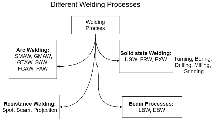
Figure 1. Welding process
Gas welding is also named oxy-fuel gas welding (OFW). Gas welding derives heat from the combustion of fuel gas such as acetylene in combination with oxygen. The process is a fusion welding process where the joint is completely melted to obtain the fusion. Necessary considerations for gas welding.
Fuel Gases
Fuel gas for Gas welding used is acetylene due to its high temperature in the flame. Thereby the gas welding may be known as oxy-acetylene welding (OAW).
4.3.1 Oxy Acetylene Welding
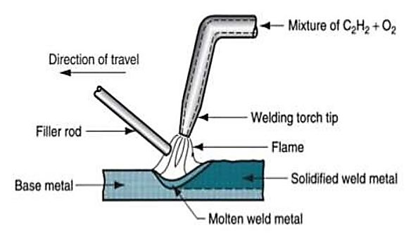
Figure 2. Gas Welding
Working principle of Gas Welding:
4.3.2 Resistance Welding
Resistance welding processes differ from other welding processes in that no fluxes are employed, the filler metal is rarely used, and the joints are often of the lap type. The amount of heat generated in the workpiece depends on the magnitude of the current, the resistance of the current-conducting path, and the time for which the current is made to flow.
This is expressed in terms of joule heating. By the simple application of Ohm’s law, the voltage (V) required for a current flow (I) is given by the relationship
V = IR,
where R is the resistance offered by the workpiece to the flow of current.
The heat generated is, thus, expressed by the formula:
H = IVt
= I (IR) t
= I2 Rt
where, H = heat generated, joules
I = current, rms amperes
R = resistance, ohms
t = time of current flow, seconds.
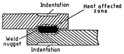
The heat generated is, thus, directly proportional to the resistance offered by any point in the circuit. As the interface of the two surfaces forming the lap joint is the point of greatest resistance, it is also the point of greatest heat. In simple resistance welding processes, a low voltage high amperage current flows from one adjoining plate to the other until the metal at the interface is heated to a high enough temperature to cause localized fusion which under the applied pressure squeezes the molten metal from the two parts to a homogenous mass called the weld nugget, as shown in Fig.
Figure 3.Resistance Welding
4.3.3 Spot and Steam Welding
Resistance Spot Welding:
In this process, overlapping sheets are joined by local fusion, at the interface, by the concentration of current flowing between two electrodes. It is characterized by low cost, high speed, and dependability making it, at present the most widely used resistance welding process. high enough the essential features of the process, and the basic circuit components are shown in Fig.
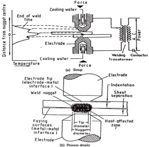
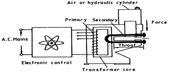
Figure 4. Resistance spot welding
Spot Welding Sequence:
All resistance welding operations are automatic, and therefore all process variables are pre-set, and maintained constant. Once a welding operation has been initiated there is no way in which its progress can be controlled, and, thus, the weld cycle is completed as per the pre-set times.
Welding Cycle:
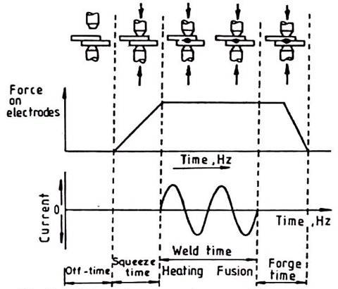
The welding cycle for spot, seam, and projection welding consists basically of four elements viz., squeeze time, weld time, hold time, and off time. These timings are pre-set for a particular metal, and a thickness range and the shop operator normally cannot change them on his own. Each one of these four-time phases has its role to play in achieving a sound weld of the required size.
Squeeze Time:
The time interval between the application of electrode pressure to the work, and switching on the welding current is called the squeeze time. This time interval is provided to assure the contact between the electrode, and the work, and to initiate the application of force on it.
Weld Time:
It is the time for which the welding current flows to melt the metal at the interface.
Hold Time:
It is the time for which the electrodes are kept in position, after the welding current is switched off, to assure the application of pressure to consolidate the molten metal into a nugget which is then cooled by the dissipation of heat to the surrounding work material. If the applied force is excessive it may result in the expulsion of molten metal from in-between the sheets.
Off Time:
The time allowed to shift the work to the next location before the cycle is repeated is referred to as the off-time. The electrodes are kept off the work during this time interval.
All these phases of a weld cycle are shown in fig.:
Figure 5. Weld cycle
Machine Rating:
The actual welding is done in the secondary circuit of the resistance welding machine but the voltage is not known, and the current flowing, for a fraction of a second for each weld cycle, is very heavy. It is, therefore, not easy or economical to measure these electrical parameters in the secondary circuit. The machine rating is, thus, based upon the current drawn by the system at the mains supply, and is given in the KVA unit. Some part of this power is lost in the system which goes to heat up the windings, and stampings.
This leads to a rise in temperature of the transformer which necessitates water cooling of the system otherwise the insulation may get damaged. To give a higher margin of safety the KVA ratings of these machines are quoted based upon the power that can be drawn for thirty seconds in each minute, this accounts for the cooling requirements of the system. The KVA rating of the resistance welding machines for spot, seam, and projection welding, normally varies between 5 to 500 KVA.
Spot Welding Electrodes:
Electrodes are an important part of a resistance spot welding unit. They serve four important functions viz., conduct the welding current to the work, transmit the desired force to the workpieces, dissipate a part of the heat from the work, and provide jigging action to it.
To achieve the desired current density, it is important to have a proper electrode shape for which three main types of electrodes are used; these are pointed, domed, and flat electrodes.
Pointed tips are most widely used particularly for ferrous materials; with continued wear, they mushroom uniformly. The pointed electrodes are basically truncated cone electrodes with an angle of 120° – 140°. Compared with other types, the contact area can be controlled more accurately with a truncated cone or pointed electrodes, and any wear in service can be easily seen. However, the pointed tip electrodes make more obvious surface marking on the workpiece, and require more accurate alignment.
Domed electrodes are characterized by their ability to withstand heavier pressure and severe heating without mushrooming which makes them particularly useful for welding non-ferrous metals. The radius of the dome varies but a 50 to 100 mm radius is most commonly used. Filing of electrodes while on the machine should not be permitted as it is not possible to reproduce their original shape by that method.
When inconspicuous or invisible welds are desired or where the weld indentation is to be minimum, a flat lip electrode is used. A combination of one flat and one domed electrode is usually used in such cases. All three types of electrodes are shown in Fig.
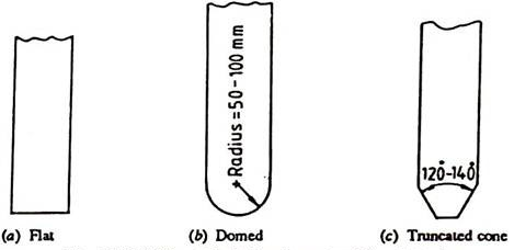
Figure 6. Spot Welding
Offset electrodes can be used to make spot welds in places that are inaccessible to weld by conventional type electrodes e. g., for making comer welds, and for welding parts with overhanging flanges as shown in Fig. 11. If there is excessive off-set undue tip deflection, skidding, and surface deformation may result. If the size of the electrode is restricted to accommodate the joint, overheating may result.
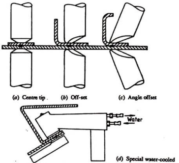
Figure 7. Spot Welding Electrodes
Spot welding electrodes are made of materials with higher electrical, and thermal resistivities, and with sufficient strength to withstand high pressure at elevated temperatures, for example, copper-base alloys such as copper beryllium, and copper tungsten are often chosen for the purpose.
4.3.4 Arc Welding
Carbon arc welding (CAW) is a process which produces coalescence of metals by heating them with an arc between a non- consumable carbon (graphite) electrode and the work-piece. It was the first arc-welding process developed but is not used for many applications today, having been replaced by twin-carbon-arc welding and other variations. The purpose of arc welding is to form a bond between separate metals. In carbon-arc welding a carbon electrode is used to produce an electric arc between the electrode and the materials being bonded. This arc produces temperatures in excess of 3,000 °C. At this temperature the separate metals form a bond and become welded together.
4.3.5 Metal Arc
Manual metal arc welding
In this process, the heat is generated by an electric arc between base metal and a consumable electrode. As the electrode movement is manually controlled hence it is termed as manual metal arc welding. This process is extensively used for depositing weld metal because it is easy to deposit the molten weld metal at right place where it is required, and it doesn’t need separate shielding. This process is commonly used for welding of the metals, which are comparatively less sensitive to the atmospheric gases. This process can use both AC and DC. The constant current DC power source is invariably used with all types of electrode (basic, rutile and cellulosic) irrespective of base metal (ferrous and non-ferrous). However, AC can be unsuitable for certain types of electrodes and base materials. Therefore, AC should be used in lights of manufacturer recommendations for electrode application. In case of DC welding, heat liberated at anode is generally greater than the arc column and cathode side. The amount of heat generated at the anode and cathode may differ appreciably depending upon the flux composition of coating, base metal, polarity and the nature of arc plasma. In case of DC welding, polarity determines the distribution of the heat generated at the cathode and anode and accordingly the melting rate of electrode and penetration into the base metal are affected.
4.3.6 TIG and MIG Welding
Tungsten inert gas (TIG) welding or gas tungsten arc is an inert gas shielded arc welding using a non-consumable electrode. This electric arc is produced by the passage of current through a conductive ionized inert gas that provides shielding of the electrode, molten weld pool, and solidifying weld metal from contamination by the atmosphere. The process may be used with or without the addition of filler metal using metal rods. (a) The gas tungsten arc welding process, formerly known as TIG (for tungsten g inert-gas) welding. (b) Equipment for gas tungsten-arc welding operations.
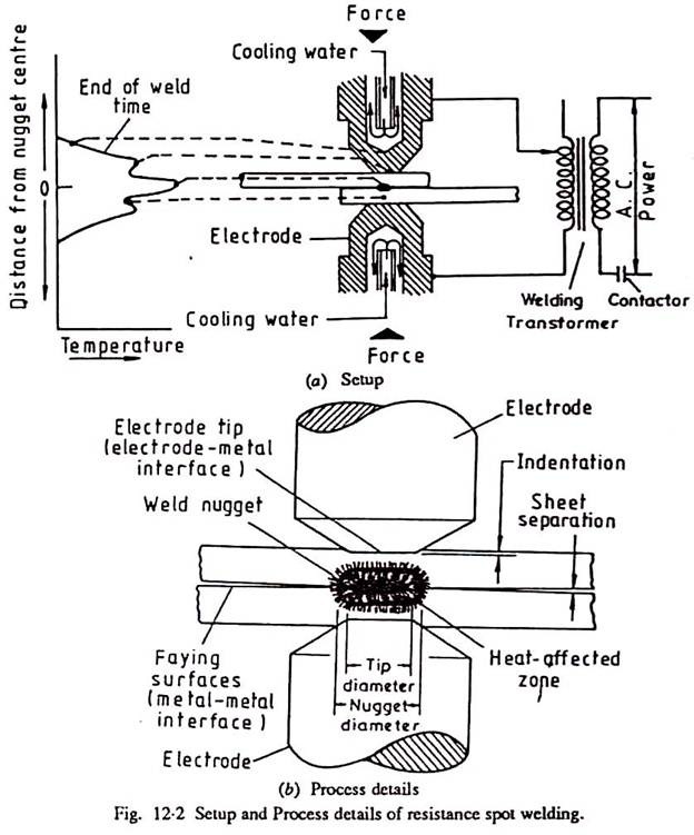
Figure 8. TIG welding
Electrode: In TIG welding, tungsten refers to the element used on the electrode. The function of the electrode is to serve as one of the electric terminals which supply the heat required to the weld. Care must be taken so that the tungsten electrode does not come in contact with the weld pool in any way to avoid its contamination resulting in the faulty weld. Pure tungsten is less expensive and will carry less current. Some other elements may be added to the tungsten, like cerium, lanthanum, thorium, and zirconium creating electrode alloys to improve arc stability, emissivity, and bring higher melting points. The electrode may contain 1 to 2% thoria (thorium oxide) mixed along with the core tungsten or tungsten with 0. 15 to 0. 40% zirconia (zirconium oxide). The thoriated tungsten electrodes carry a high current, and more desirable as they can strike, and maintain a stable arc. The zirconia added with tungsten is better than pure tungsten but inferior to the thoriated tungsten electrode.
Tungsten inert gas welding set up: It consists of a welding torch at the center of which is the tungsten electrode. The inert gas supplied to the welding zone through the annular path surrounding the tungsten electrode to effectively displace the atmosphere around the weld puddle.
MIG
This is also known as Metal inert-gas arc welding (MIG) because it utilizes a consumable electrode. Other gas-shielded arc-welding processes are utilizing consumable electrodes such as flux-cored arc welding, all of which coming under MIG. It’s quite stable for thicker sheets because filler metal requirement in the welding process makes gas-tungsten arc welding (GTAW or TIG) difficult to use, which is more suitable for thin sheets. (a) Schematic illustration of the gas metal-arc welding process, formerly known as MIG (for metal inert-gas) welding. (b) Basic equipment used in gas metal-arc welding operations.
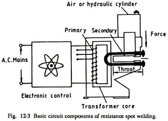
Figure 9. MIG welding
The consumable electrode is in the form of a wire reel fed at a constant rate through the feed rollers. The welding torch is connected to the gas supply cylinder, which provides the necessary inert gas. The electrode and the work piece are connected to the welding power supply. The power supply is always of the constant voltage type. The current from the welding machine is changed by the rate of feeding of the electrode wire. Normally, DC arc-welding machines are used for GMAW with electrode positive (DCEP). The DCEP increases the metal- deposition rate, and also provides a stable arc and smooth electrode metal transfer. With DCEN the arc becomes highly unstable, and also results in spatter. But special electrodes having calcium, and titanium oxide mixtures as coatings are found to be good for steel with DCEN.
Metal Transfer
The short-circuiting metal transfer occurs with relatively low current settings of the order of 75 to 175 A for an electrode diameter of 0. 9 mm. The number of times that the pinching takes place depends on the inductance of the welding machine used, and the parameters set. The rate at which the short-circuiting current increases is controlled by the inductance of the welding machines. Too low an inductance gives rise to a very high short-circuiting current, and consequently a high pinching rate. With high inductance, the short-circuiting becomes low and results in a somewhat lower pinching force. The effect of inductance is measured in terms of response rate (raising rate of current due to short-circuiting, kA/s). It can be observed that the optimum response rate depends on the electrode wire size. Hence, he is welding machines to be used for short-circuiting transfer make use of a variable choke system which can be tuned for different wire sizes. The frequency of metal transfer may be of the order of 50 to 200per second. This rate also depends on the open-circuit voltage, and wire-feed rate employed.
Shielding gases
Argon, helium, nitrogen, oxygen, carbon dioxide, and a mixture of the above gases in various proportions are used in GMAW as shielding gases. Argon is the most widely used of all the shielding gases, because it reduces the spatter, and concentrates the arc, which in turn gives deep penetration welds. Besides, argon ionizes easily requiring smaller arc voltages, and also has lower thermal conductivity, and hence conducts heat very slowly from the arc to the weld zone. Thus, it is good for welding thin sheets. Because of the lower voltages employed, it is suitable for out-of-position welding. For spray transfer of metal, a large percentage of argon is required. Helium is the most expensive of all the shielding gases. Due to its better thermal conductivity, it is suitable for thicker sheets as well as for metals having higher thermal conductivity such as copper, and aluminum. The filler metal-deposition rate by helium is much higher compared to argon because of the higher current-carrying capacity. The arc in carbon dioxide shielding gas is unstable, and therefore a short arc is to be used to reduce the metal spatter. It is the least expensive of all the shielding gases. Since about 7. 5% of the carbon dioxide decomposes into carbon monoxide, and oxygen in the arc, deoxidizers such as aluminum, and silicon are to be used while using carbon dioxide. It is a heavy gas, and therefore it covers the weld zone very well. The metal transfer is globular only with the carbon dioxide shielding gas. Sometimes the mixtures of gases such as argon-helium, argon-carbon dioxide, argon-oxygen are used for special applications. Shielding gases should always flow in a laminar manner without causing any turbulence because turbulence causes weld contamination. The gas flow rates to be used depend upon the thickness of the sheet being welded, the position of the weld as well as the base material.
Electrodes
The electrode wire comes generally in the form of coils, and normal sizes may be of the order of 0. 5 to 3. 2 mm. Depending upon the base material, various wire compositions are available. For steels, electrodes wire having deoxidizers are used because the deoxidizers help in the reduction of oxidation of the weld metal as well as the porosity. The electrode wire is produced by wire drawing, and uniform diameter throughout otherwise the arc may saunter.
4.3.7 Welding Defects and Remedies
Welding Defects can be defined as the irregularities formed in the given weld metal due to wrong welding process or incorrect welding patterns, etc. The defect may differ from the desired weld bead shape, size, and intended quality. Welding defects may occur either outside or inside the weld metal. Some of the defects may be allowed if the defects are under permissible limits but other defects such as cracks are never accepted.
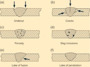
Figure 10. Welding
Defects in welding joints are classified into 2 broad categories.i.e., those that occur internally and those that occur externally.
External Welding Defects
External defects are also known as surface of visual defects because they manifest themselves on the surface itself. They include surface cracks, overlaps, undercuts, porosity, and spatter. We will discuss each one of them in the next section.
i. Cracks
Cracks are the most common defects and they can occur anywhere on the surface of the weld material. Some cracks can also be present inside the weld material especially on areas that are affected by direct heat (HAZ). Cracks presents themselves in two major types:
Causes of Cracks
Remedies
ii. Overlaps
Overlap results when the weld pool overflows on the surface of the weld metal. The molten metal does not fuse with the base metal leading to an overlap which may extend to form an angle not exceeding 90 degrees.
Causes of Overlaps
Remedies
iii. Undercuts
Undercuts presents themselves as narrow gutters on the base metal next to the weld metal near the edge. This occurs when the base metal melts away from the weld area reducing the thickness of the base metal and the result is a weakened workpiece. These undercuts run parallel to the metal weld.
Causes of Undercuts
Remedies
iv. Porosity
Porosity is a condition that manifests itself inform of gases or air bubbles that are trapped in the weld metal. It is mainly as a result of contamination of the weld metal which is weakened and it can actually collapse with time.
Causes of Porosity
Remedies
v. Spatter
Spatter occurs when metal particles from the weld is stuck on the area adjacent to the weld area. This defect is common in gas metal arc welding and it is sometimes very hard to remove the particles.
Causes of Spatter
Remedies
Internal Welding Defects
These are defects that occur at some depth in the material. They are visually invisible since they are not present on the surface but they carry equal weight as the external ones. These defects include incomplete fusion, slag inclusion, and incomplete penetration.
i. Incomplete Fusion
Lack of fusion or incomplete fusion occurs when the weld metal and the base metal are not accurately welded due to improper melting resulting into unfilled gap. Improper fusion can also occur between layers within the weld itself. Although this is an internal problem, it can be manifested on the outer surface too if the outer sidewall is not properly fused with the parent metal.
Causes of Incomplete fusion
Remedies
ii. Incomplete Penetration
Incomplete penetration results when the depth of the weld is not sufficient. As such, the metal grove is not filled fully meaning that the weld does not extend through the entire joint.
Causes of an Incomplete Penetration
Remedies
vi. Slag Inclusion
Slag inclusions are compounds such as oxides that are mainly trapped in the weld or on the surface of the weld zone. These compounds are byproducts of welding processes such as stick welding and arc welding. In addition, insufficient cleaning can leave some slag behind which reduces the strength of the weld and also it can act as a starting point of serious cracking. Serious slag inclusion may require you to do a re-weld.
Causes of Slag Inclusion
Remedies
Soldering
soldering is a process of joining two metals by using another low temperature metal alloy. The metal used for the joining purpose is called solder. Solders are of two types:
hard solder is an alloy of copper and zinc whereas the soft solder is an alloy of tin and lead.
Process
The surfaces to be joined are cleaned and are placed on each other. A fluxes employed to prevent oxidation. Zinc chloride is commonly used for this purpose. The soldering iron is heated either electrically or by some external heat. Then the heart and is dipped into the flux and solder is pressed against the surfaces to be joined. A joint is formed by melting the solder.
Applications
soldering is widely used for sheet metal work and in radio and television work for joining wires.
Advantages
Disadvantages
Brazing
The process of joining two metal surfaces by heating, and adding a non-ferrous alloy with a melting point above 400-degree Celsius is known as brazing.
Process
The surfaces to be joined are cleaned from all oil, dirt oxides. Then both the surfaces are placed in the joining position. Flux is sprinkled or placed on it. The heat is given to the surface and the filler metal. The molten filler metal flows to the surfaces to be joined. On cooling, a brazing joint is formed. The filler metals used are copper, copper alloy, silver alloy, and Aluminium alloys. In brazing, the filler metal melts but the surfaces to be joined remain unmelted. The various methods used to melt the filler metal, and flux are:
Applications
Brazing is used for electrical items, radiators, heat exchangers comma pipes, and pipe fittings, and tooltips.
Advantages
Disadvantages
SR. No. | Brazing | Soldering |
1 | Filler metal has the melting point above 400°c | Filler metal has the melting point below 400°c |
2 | More stable joints can be made | Less stable joints can be made |
3 | High pressure and temperature do not affect the joint | Joints are affected by high temperature and pressure |
4 | Equipment cost is more | Equipment cost is very low. |
Sl No | Parameter | Welding | Brazing | Soldering |
1 | Temperature | Very high about more than 5000 degree c | Melting point of the filler metal is above 600 degree c | Melting point of the filler metal is below 450 degree |
2 | Type of metal to be joined | Only similar metals | Dissimiliar metals | Only similar metals |
3 | Surface finish | Moderate | Good | Poor |
4 | Strength | Very high | high | Weak |
Key points
1) Soldering is a process of joining two metals by using another low-temperature metal alloy. The metal used for the joining purpose is called solder.
2) The process of joining two metal surfaces by heating, and adding a non-ferrous alloy with a melting point above 400-degree Celsius is known as brazing.
Grinding:
Advantages:-
Anodizing:
Advantages:-
Lapping:
Characteristics of lapping process:
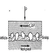
Fig11. Scheme of lapping process
Advantages:-
2. Fixed Costs – Do not vary with production rate but relate “directly” to production function.
3. General Expenses – Functions to which operations must contribute – overhead burden.
Manufacturing cost Examples:
Maintenance and Repairs: -
Supervisory and Clerical Labour: -
Depreciation: -
References:
1. Manufacturing Science - Amitabha Ghosh & Ashok Kumar Malik, - East-West Press.
2. Manufacturing Process and Systems - Ostwald, Munoz, John Wiley.
3. Workshop Technology, Vol. 1, 2 & 3 – Chapman, WAJ, Edward Arnold.
