Unit – 1
D.C. Circuit Analysis
Electric circuit: A circuit is an interconnection of electrical components.
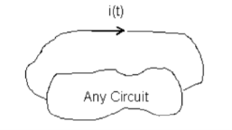
Figure 1. Circuit
Electric charge: is one of the fundamental quantities and exists in every atom.
Symbol: Q or q
Unit: Coulomb (C).
Electric Current: The time rate of change of charge.
i(t ) = dq/dt
Symbol: i t( ) or i or I depending on whether the current is constant or time varying quantity.
Unit: Ampere (A); A = 1.C / 1.s
Voltage (Potential Difference):
Voltage => Work done on q to move it from point A to point B per unit charge
=> Difference in potential energy per unit charge
Symbol: V or v(t ) v t
Unit: Volt (V); 1.V = 1.J/1.C
Power: The time rate of change of energy is defined as power.
Symbol: P or p.
Unit: Watts (W). 1 W = 1 J / 1 s.
In general i, v and p are used to represent time varying parameters.
∴ Change in energy from time t1 to t2
∆w =  =
= 
Statement - Ohm’s Law states that the current flowing through a conductor is directly proportional to the potential difference applied across its ends, provided the temperature and other physical conditions remain unchanged. Mathematically it can be represented as,
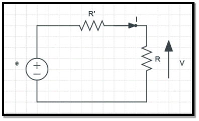
Figure 2. Ohms law
Potential difference ∝ Current
V ∝ I
(When the value of V increases the value of I increases simultaneously)
V = IR ………………………. (eq.1)
Where,
Calculating Various Parameters Using Ohm’s Law
As an equation (eq.1), the Ohm’s Law serves as master for calculating the current (I), when the resistance (R) and the potential difference (V) are known. Similarly, if any two parameters in the equation (eq.1) are known, then the unknown third one can be easily calculated as follows:
V = IR …………………………… (eq.2)
I=VR ……………………………… (eq.3)
R=VI ……………………………… (eq.4)
An independent voltage source maintains a voltage fixed or varying with time not affected by any other quantity.
Similarly an independent current source maintains a current fixed or time-varying which is unaffected by any other quantity. The usual symbols are shown in figure.

Figure 1.3: Symbols for independent sources
Some voltage or current sources have their voltage or current values varying with some other variables. They are called dependent voltage or current sources or controlled voltage or current sources, and their usual symbols are shown in figure

Figure 1.4: Symbols for dependent sources. Variables in brackets are the controlling variables whose values affect the value of the source.
A passive element is an electrical component that does not generate power, but instead dissipates, stores, and/or releases it. Passive elements include resistances, capacitors, and coils also called inductors. These components are labelled in circuit diagrams as R, C and L, respectively. In most circuits, they are connected to active elements, typically semiconductor devices such as amplifiers and digital logic chips.
The components in electrical circuits can be connected in series or in parallel.
Series connections
Components that are connected one after another on the same loop of the circuit are connected in series. The current that flows through each component connected in series is the same.
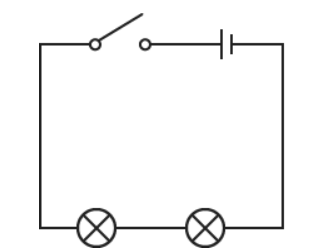
Two lamps connected in series
The circuit diagram shows a circuit with two lamps connected in series. If one lamp breaks, the other lamp will not light.
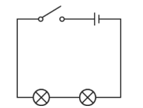
Figure 1.5 Two lamps connected in series with open switch and cell
The sum of all the potential differences across the components in a series circuit is equal to the total potential difference across the power supply.
Parallel connections
Components that are connected on separate loops are connected in parallel. The current is shared between each component connected in parallel. The total amount of current flowing into the junction, or split, is equal to the total current flowing out. The current is described as being conserved.
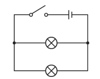
Two lamps connected in parallel
The circuit diagram shows a circuit with two lamps connected in parallel. If one lamp breaks, the other lamp will still light.
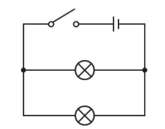
Figure 1.6 Two lamps connected in parallel
The lights in most houses are connected in parallel. This means that they all receive the full voltage and if one bulb breaks the others remain on.
For a parallel circuit the current from the electrical supply is greater than the current in each branch. The sum of all the current in every branch is equal to the current from the electrical supply.
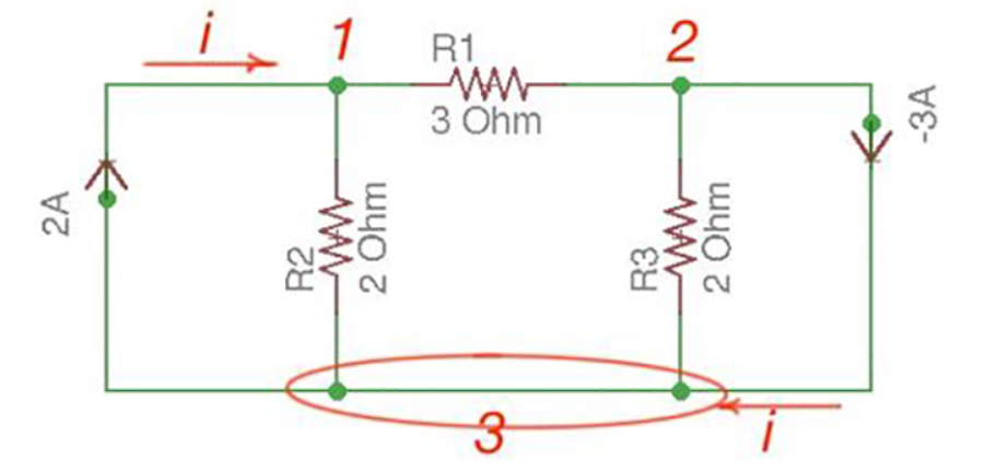
Kirchhoff’s Current Law (KCL)
Statement - The algebraic sum of currents meeting at a junction or node in a electric circuit is zero or the summation of all incoming current is always equal to summation of all outgoing current in an electrical network.
Explanation
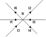
Figure 1.7 KCL
Assuming the incoming current to be positive and outgoing current negative we have


I e incoming current = ∑ outgoing current thus, the above Law can also be stated as the sum of current flowing towards any junction in an electric circuit is equal to the sum of currents flowing away from that junction.
Kirchhoff’s Voltage Law (KVL)
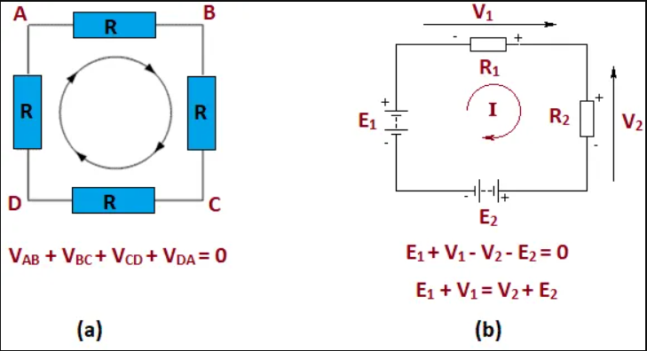
The second law of Kirchhoff’s laws is Kirchhoff’s Voltage Law. It states that in any closed loop network, the sum of the emf values in any closed loop is equal to the sum of the potential drops in that loop.
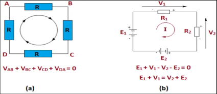
Fig. 1.8 – Kirchhoff’s Voltage Law
In another words, it can also be said as “The total voltage around the loop is equal to the sum of all the voltage drops within the same loop”, which is equal to zero.
Example :
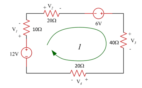
Consider the following circuit :
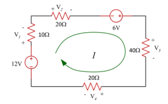
-12 + V1 + V2 -6 +V3 + V4 =0
V1+V2+V3+V4 = 12 +6
V1 + V2 + V3 + V4 = 18
The applications include:
Nodal analysis
In the nodal method we are finding the node voltages with the following steps:
Consider the following circuit.
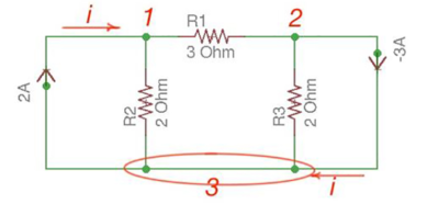
Figure 1.9 Nodal Analysis
Let us consider a reference node – 3.
In a real circuit a reference node is ground is assumed to have potential.
By the Kirchhoff’s Law having the following current relation:
I1 = i1 + i2
I2 = i2 -i3
Let us represent currents like ratio of voltage and resistance by the Ohm’s Law:
i 1 = v1 /R1 ;i 2 = v1 -v2 /R2 ; i3 = v2/R3;
or
i 1= v1 * G1 ; i2 =(v1 -v2)*G2 ; i3 =v2 * G3
i1 = v1 * G1 + (v1-v2) * G2 ;
i2 = (v1-v2) * G2 – v2 * G3
i1= v1 * (G1 +G2) – v2 * G2
i2 = v1 *G2 – v2 *(G3 +G2)
or
And we achieve the following matrix equation, which can be resolved by the Cramer’s rule:
[ G1 + G2 -G3 -G3 ] [v1] = [I1]
[ G2 -G2][v2] =[I2]
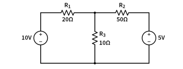
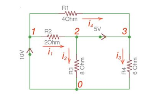
Consider the following figure :
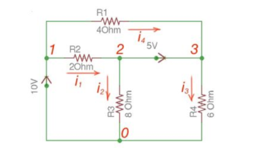
Figure 10. Mesh circuit
There are two possibilities that exist:
Applying Kirchhoff’s Law we achieve the following equations:
i 1 + i4 = i2 + i3
-v2 +5+v3 =0
v 1 =10
By Ohm’s Law
These equations will help determine node voltages.
Loop Analysis
Loop analysis is a special application of KVL on a circuit. We use a special kind of loop called a 'mesh' which is a loop that does not have any other loops inside of it. A mesh starts at a node and traces a path around a circuit, returning to the original node without hitting any nodes more than once. We can only apply mesh analysis to planar circuits, that is circuits without crossover connections. If a circuit cannot be redrawn without the intersecting disconnected lines then we cannot use mesh analysis.
Superposition Theorem
Question 1. Find the current through  resistance.
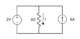
Solution:
 1= 0
1= 0
 2=
2=
 1 +
1 +  2
2 
Special Case:
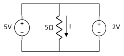
Since two voltage sources with different magnitude in parallel which cannot be connected as in single branch two different current is not possible (if 5V than I = zero).
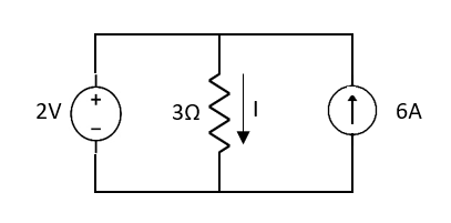
Question:
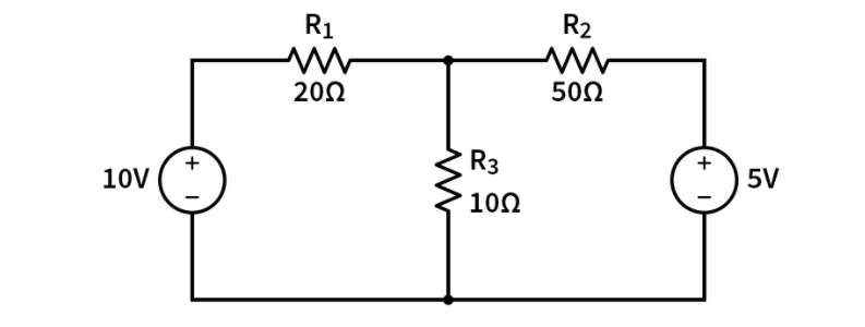
 1 =
1 = 
 2 =
2 = 
=
 1 +
1 +  2
2
= 
Thevenin’s and Norton’s Theorem
Thevenin’s equivalent of A
Norton’s equivalent of A
 sc = Vth/Rth
CONDITIONS FOR APPLICATION
Method for finding Rth :
Firstly, open circuit terminal A and B.
2. If network A is operating with independent and dependent sources:
3. If network is operating with only dependent sources:
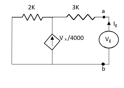
Connect generation between A and B

Method for Vth:
First open circuit terminal A and B.
Find out the voltage between A and B this is Vth
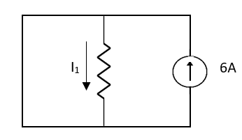
Method for Isc:

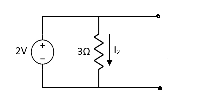
Question:
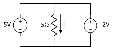
Answer:
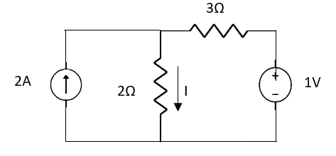


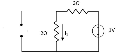


Finding Isc from circuit directly:
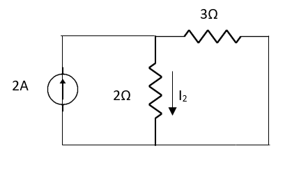
By KCL,


Question:
Answer
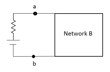
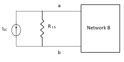
Also, clear from circuit that Vth = 1V.
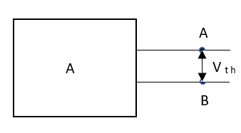
By applying KVL we get,
1-3Isc=0
Isc= A
A
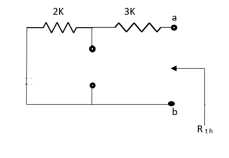
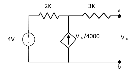
Que:
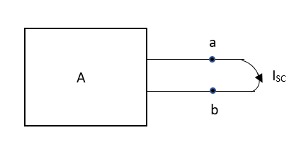
Ans;
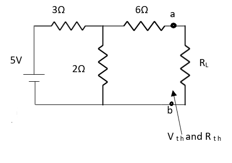
Rth=3k+2k=5k
By applying KVL we get


Therefore, 
Question:
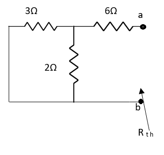
Solution: For Rth
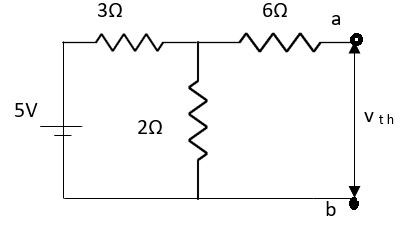
By KCL,


But, 


By KVL,


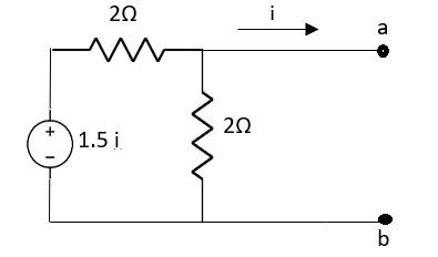
Question:
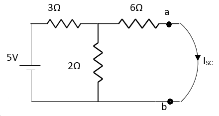
Solution: Since, no independent source is present so,
Isc = 0
And we know that,


Since Rth cannot be zero
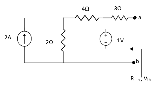


But 


Question: Find out the Norton’s equivalent
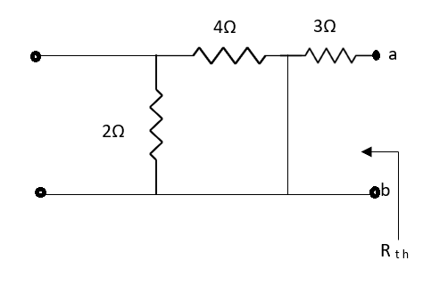
Solution:
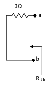
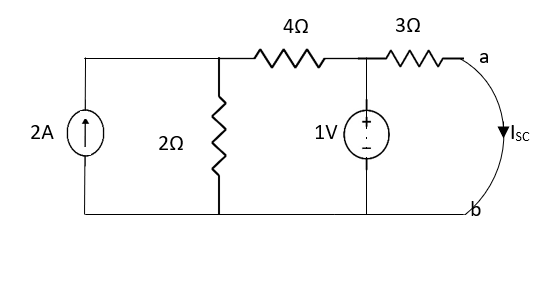

Since, there is no significance of current source


Figure 12. Reciprocity theorem
The resistances R1, R2 and R3 is connected in the circuit diagram. It is clearly shown the voltage and current sources are interchanged for solving the network.
Step 1 – Firstly, select the branches between which reciprocity is established.
Step 2 – The current in the branch is obtained using any conventional network analysis method.
Step 3 – The voltage source is interchanged between the branch which is selected.
Step 4 – The current in the branch where the voltage source was existing earlier is calculated.
Step 5 – Hence it is seen that the current obtained in the previous connection, that is step 2 and the current which is calculated when the source is interchanged, that is step 4 are identical to each other.
Problem:
Verify the reciprocity theorem for the given network.
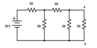
Find the current in branch AB
RT = 2+[3||(2 + 2 || 2)
RT = 3.5 Ω
IT = V / RT = 20/3.5 = 5.71 A
Apply current division technique for the circuit to find the current through branch AB
= 5.71 x 3 / 6 = 2.855 A
Current in branch AB = 2.855 x 2/4 = 1.43A
Interchanging the source to branch AB
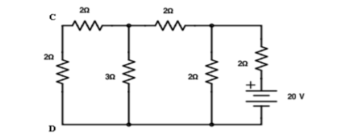
Total resistance RT = 3.23Ω IT = 20/3.23 = 6.19A
Apply current division technique for the circuit to find current through branch CD = 6.19 x 2/5.2 = 2.38A
Current in branch CD = 2.38 x 3/5 = 1.43A
Hence reciprocity theorem verified.
Verify the reciprocity theorem for the given circuit:
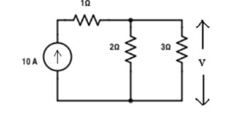
Apply current division technique for the circuit to find current through branch 3Ω
= 10 x 2 / 5 = 4 A.
Voltage across 3Ω = 4 x 3 = 12 V
Replace the current source and find the open circuit voltage.
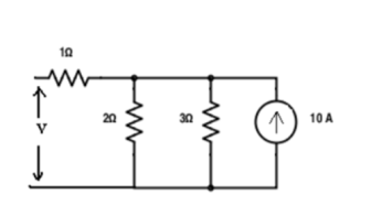
Apply current division technique and find the current through 2 Ω resistor.
= 10 x 3 / 5 = 6
Voltage across 2Ω resistor = voltage across AB = 6 x 2 = 12 V
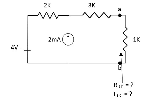
Figure 13. Maximum Power Transfer

where Rth is Thevenin’s equivalent resistance across a and b.
Maximum power is absorbed by ZL when
Condition: 


Comparing real and imaginary parts


OR


Maximum power absorbed by ZL is


Question: Find out the value of load resistance if power absorbed is maximum.
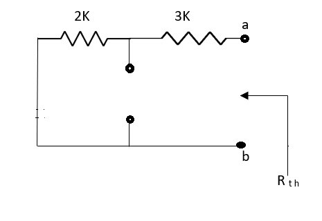
Solution: find Thevenin’s equation



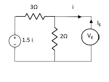
Question: Find maximum power delivered is RLif its value is

Solution


Therefore, 
Millman’s Theorem
In other words; it determines the voltage across the parallel branches of the circuit have more than one voltage sources which reduces the complexity of the electrical circuit.
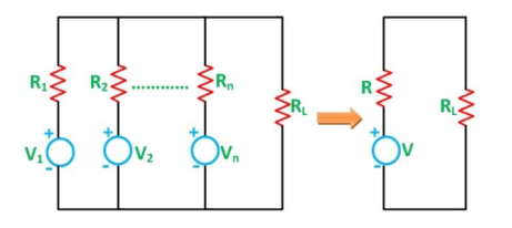
Figure 14. Millmans theorem
V =  V1 G1
V1 G1  V2 G2
V2 G2  ………………………
  Vn Gn / G1 + G2 ……………+Gn
And
R = 1/G = 1/ G1 + G2 + …………………..+Gn
Assuming a DC network of numerous parallel voltage sources with internal resistances supplying power to a load resistance RL as shown in the figure below
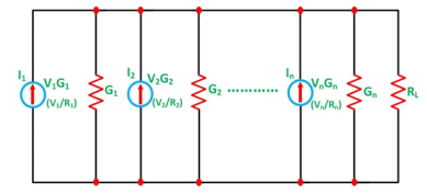
Figure 15. DC network
Let I represent the resultant current of the parallel current sources while G the equivalent conductance as shown in the figure below
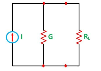
Figure 16. Equivalent
I = I1 + I2 + I3 + …………………….. and
G = G1 + G2 + G3 + …………………
Next, the resulting current source is converted to an equivalent voltage source as shown in the figure below
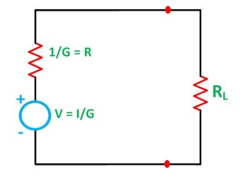
Figure 17.Final circuit
Thus,
V = 1/G =  I1
I1  I2
I2  ……………………
 In / G1 + G2 + ………………..+ Gn
Positive (+) and negative (-) sign appeared to include the cases where the sources may not be supplying current in the same direction.
Also,
R = 1/G = 1/ G1 + G2 +………………….+ Gn
And as we know,
I = V/R, and we can also write R = I/G as G = I/R
So, the equation can be written as
V =  V1/R1
V1/R1  V2 / R2
  ……………………
 Vn/Rn / 1/R1 + 1/R2 +……………..+1/Rn
Where R is the equivalent resistance connected to the equivalent voltage source in series.
Thus, the final equation becomes
V =  V1G1
V1G1  V2 G2
V2 G2  ……………………
 VnGn / G1 + G2 +……………..+Gn or
V =  /
/  and Gk = 1/Rk
Steps for Solving Millman’s Theorem
Following steps are used to solve the network by Millman’s Theorem
Step 1 – Obtain the conductance (G1, G2,….) of each voltage source (V1, V2,….).
Step 2 – Find the value of equivalent conductance G by removing the load from the network.
Step 3 – Now, apply Millman’s Theorem to find the equivalent voltage source V by the equation shown below
V =  V1G1
V1G1  V2 G2
V2 G2  ……………………
 VnGn / G1 + G2 +……………..+Gn
Step 4 – Determine the equivalent series resistance (R) with the equivalent voltage sources (V) by the equation
R = 1/G
Step 5 – Find the current IL flowing in the circuit across the load resistance RL by the equation
IL = V / R + RL
Star to delta conversion to final equivalent resistance
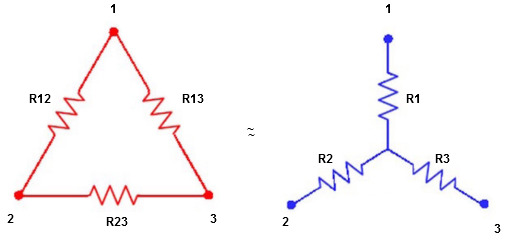
Figure 18. Delta to star
We know that (from delta to star conversion)
R1 =  …….①
…….①
R2 =  …..②
…..②
R1 =  ……③
……③
Multiply ① X ② L.H.S and R.H.S
R1 R2 =  …….④ where
Similarly multiply ② X ③
R2 R3 =  …….⑤
…….⑤
And ③ X①
R1 R3 =  …….⑥
…….⑥
Now add equation ④, ⑤, and ⑥ L.H.S and R.H.S


 ……refer eq. ②
 =
=  +
+  +
+ 
 =
=  +
+ 

(Delta) star star
Similarly R23 = R2+R3 + 
R23 = R1+R2 + 
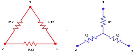
Delta  Star
Star
= R12// (R23 + R13) =R1 + R2
= 
 = R1 + R2
= 

Here let R = R12 + R23 + R13
= 
 R2 + R3

 R1 + R3
Now the 3 equations after equating L.H.S. and R.H.S
R1 + R2 =  …….①
…….①
R2 + R3 =  ……②
……②
R1 + R3 =  …..③
…..③
Now subtract ② and ① on L.H.S. and R.H.S
R2+ R3 – R1 – R2 = 
 R3 – R1 =
  …..④
…..④
Now add equation ④ and ③
R3 – R1 + R1 + R3 = 
2R3 = 

Similarly R1 = 
And R2 = R23 R12/R where R = R12 + R23 + R13
ie star equivalent from delta network is ratio of product of adjacent branches in delta to the addition of all branches in delta.
Maximum power transfer theorem:
The circuit as shown in figure provides power to the load 27. This can be viewed as simulating a power amplifier delivering power to a complex load. It is the Thevenin equivalent of a more complex circuit. Calculate and plot a graph of the power delivered to the load for each of the following frequencies: 10 kHz, 30 kHz, 50 kHz, 80 kHz, and 100 kHz.
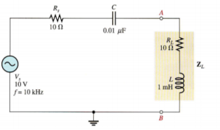
Figure 20. Maximum Power Transfer
For f= 10 kHz,
Xc = 1/ 2  f C = 1/ 2
  (10kHz) (0.01 μ F) = 1.59 kΩ
XL = 2 π f L = 2  (10KHz) (1mH) = 62.8 Ω
The magnitude of the total impedance is
Ztot =  (Rs + RL) 2 + (XL – Xc) 2 =
  (20 Ω) 2 + (1.53 k Ω) 2 = 1.53 k Ω
The current is
I = Vs / Ztot = 10/1.53k = 6.54 m A
The load power
PL = I 2 RL = (6.54 m A) 2 x 10 Ω = 428 μ W
For f=30KHz
Xc = 1/2∏(30kHz)(0.01μF)
XL = 2 ∏ (30kHz) (1mH) = 189 Ω
Zout =  (20 Ω) 2 + (342Ω) 2 = 343 Ω
I = Vs / Zout = 10V / 343 Ω = 29.2 m A
PL = I 2 RL (29.2 mA) 2 (10 Ω) = 8.53 m W
F=50kHz
Xc = 1/2∏(50kHz)(0.01μF)=318Ω
XL = 2 ∏ (50kHz) (1mH) = 314 Ω
Zout =  (20 Ω) 2 + (4Ω) 2 = 20.4 Ω
I = Vs / Zout = 10V / 20.4 Ω = 490 m A
PL = I 2 RL (490 mA) 2 (10 Ω) = 2.40 m W
For f =80kHz
Xc = 1/2∏(80kHz)(0.01μF)=199Ω
XL = 2 ∏ (80kHz) (1mH) = 503 Ω
Zout =  (20 Ω) 2 + (304Ω) 2 = 305 Ω
I = Vs / Zout = 10V / 305 Ω = 32.8 m A
PL = I 2 RL (490 mA) 2 (10 Ω) = 10.8 m W
F=100kHz
Xc = 1/2∏(100kHz)(0.01μF)=159Ω
XL = 2 ∏ (100kHz) (1mH) = 628 Ω
Zout =  (20 Ω) 2 + (304Ω) 2 = 469 Ω
I = Vs / Zout = 10V / 305 Ω = 21.3 m A
PL = I 2 RL (490 mA) 2 (10 Ω) = 4.54 m W
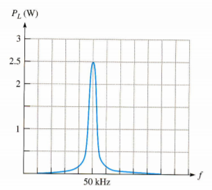

Figure 21: Open new schematic
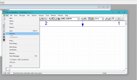
Figure 22: Saving schematic

Figure23 : Getting new part
the figure below,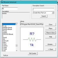
Figure 24: Place resistor
with each other. the resistors.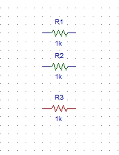
Figure : Resistors placed
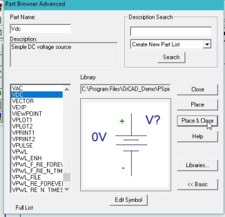
Figure 25. Input dc placed
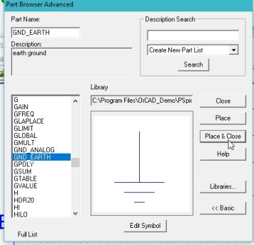
Figure 26: Ground placed
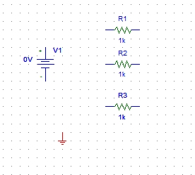
Figure 27: Placed components
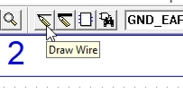
Figure 28: Drawing wire
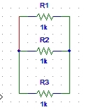
Figure 29: Parallel resistor
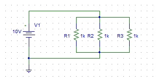
Figure 30: Complete circuit diagram
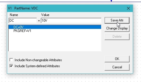
Figure 31: DC attributes
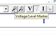
Figure 32: Voltage marker
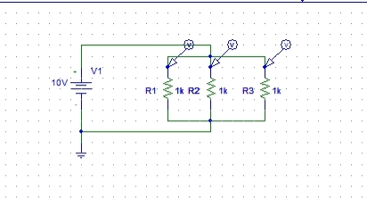
Figure 33: Voltage marker placed
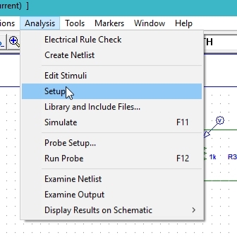
Figure 34: Analysis setup
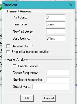
Figure 35.Transient properties
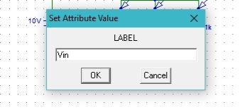
Figure 36: Labeling the wire
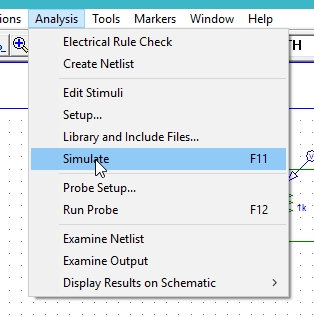
Figure 37: simulation
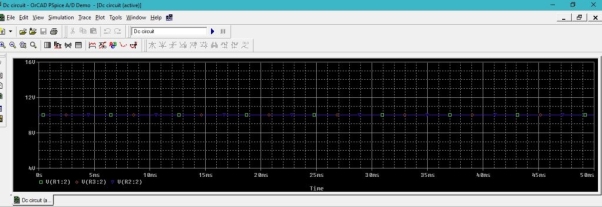
Figure38 : Output Voltages
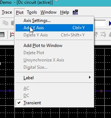
Figure39 : Adding Y axis
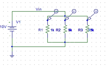
Figure40 : Updating resistance value

Figure 41: Current marker

Figure 42: Current output
References
Basic Electrical Engineering Book by I.J. Nagrath
Objective Electrical Technology Book by Rohit Mehta and V.K. Mehta