Unit – 3
Three Phase Circuits and Measuring Instruments
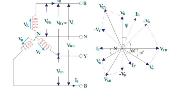
Figure 1. Three Phase
Suppose due to load impedance the current lags the applied voltage in each phase of the system by an angle ϕ. As we have considered that the system is perfectly balanced, the magnitude of current and voltage of each phase is the same. Let us say, the magnitude of the voltage across the red phase i.e. magnitude of the voltage between neutral point (N) and red phase terminal (R) is VR.
Similarly, the magnitude of the voltage across yellow phase is VY and the magnitude of the voltage across blue phase is VB.
In the balanced star system, magnitude of phase voltage in each phase is Vph.
∴ VR = VY = VB = Vph
We know in the star connection, line current is same as phase current. The magnitude of this current is same in all three phases and say it is IL.
∴ IR = IY = IB = IL, here, IR is line current of R phase, IY is line current of Y phase and IB is line current of B phase. Again, phase current, Iph of each phase is same as line current IL in star connected system.
∴ IR = IY = IB = IL = Iph.
Now, let us say, the voltage across R and Y terminal of the star connected circuit is VRY.
The voltage across Y and B terminal of the star connected circuit is VYB<!–
The voltage across B and R terminal of the star connected circuit is VBR.
From the diagram, it is found that
VRY = VR + (− VY)
Similarly, VYB = VY + (− VB)
And, VBR = VB + (− VR)
Now, as angle between VR and VY is 120o(electrical), the angle between VR and – VY is 180o – 120o = 60o(electrical).
VL = |VRY| = √ VR2 + VY2 + 2 VRVY cos 60
= √ Vph 2 + Vph 2 + 2 Vph.Vph x ½
= √3 Vph
VL = √3 Vph
Thus, for the star-connected system line voltage = √3 × phase voltage.
Line current = Phase current
As, the angle between voltage and current per phase is φ, the electric power per phase is
Vph Iph cos ɸ = VL/√3 IL cos ɸ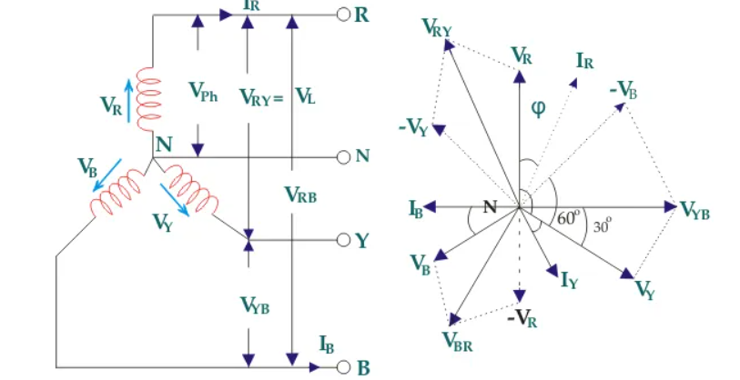 So the total power of three phase system is
3 x VL/√3 IL cos ɸ = √3 VL IL cos ɸ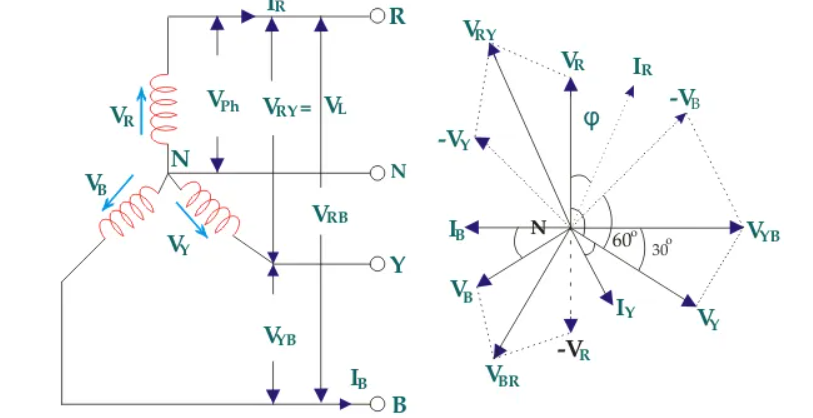
Consider equation ①
Note : we are getting resultant line current IR by subtracting 2 phase currents IRY and IBR  take phase currents at reference as shown
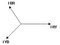
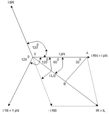
Cos 300 = 
 =
= 

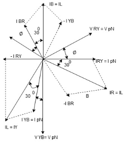
Figure 2. Balanced star and delta
Phase current IYB lags behind VYB which is phase voltage as the load is inductive
PPh = VPh IPh Cos Ø
For 3 Ø total power is
PT= 3 VPh IPh Cos Ø …….①
For star
VL and IL = IPh (replace in ①)
 PT = 3
  IL Cos Ø
 PT = 3
  VL IL Cos Ø – watts
For delta
VL = VPh and IL =  (replace in ①)
PT = 3VL
= 3VL  Cos Ø
Cos Ø
 PT
PT VL IL Cos Ø – watts
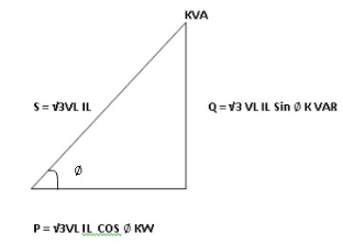
total average power
P =  VL IL Cos Ø – for ʎ and
  load
load
K (watts)
Total reactive power
Q =  VL IL Sin Ø – for star
  delta load
K (VAR)
Total Apparent power
S =  VL IL – for star
  delta load
K (VA)
In star and power in delta
Consider a star connected balance load with per phase impedance ZPh
we know that for
VL = VPh andVL =  VPh
VPh
now IPh = 
 VL = =
And VPh = 
 IL =
IL =  ……①
……①
Pʎ =  VL IL Cos Ø ……②
Replacing ① in ② value of IL
 Pʎ =
Pʎ =  VL IL
VL IL  Cos Ø
Cos Ø
 Pʎ =
Pʎ =  ….A
….A
IPh = 
 IPh = =
And IL =  IPh
IPh
 IL =
IL =  X
X  …..①
…..①
P =
=  VL IL Cos Ø ……②
Replacing ② in ① value of IL
P =
=  Cos Ø
Cos Ø
 P
P =
=  …..B
…..B

Pʎ from …A
 …..C
…..C
 =
=  P
P
We can conclude that power in delta is 3 time power in star from …C
Or
Power in star is  time power in delta from ….D
For star VPh = 
For delta VPh = VL
2. Calculate IPh using formula
IPh = 
3. Calculate IL using relation
IL = IPh - for star
IL =  IPh - for delta
4. Calculate P by formula (active power)
P =  VL IL Cos Ø – watts
5. Calculate Q by formula (reactive power)
Q =  VL IL Sin Ø – VAR
6. Calculate S by formula (Apparent power)
S =  VL IL– VA
The most important three-phase power equations relate power (P, in watts) to current (I, in amps), and depend on the voltage (V). There is also a “power factor” (pf) in the equation that takes account for the difference between the real power and the apparent power supplied to the circuit. Most types of three-phase power calculations are performed using this equation:
P = √3 × pf × I × V
Two Wattmeter Method can be employed to measure the power in a 3 phase, three-wire star or delta connected the balanced or unbalanced load.
In two wattmeter method, the current coils of the wattmeter are connected with any two lines, say R and Y and the potential coil of each wattmeter is joined on the same line, the third line that is B as shown below in
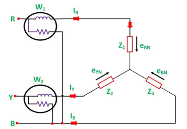
Figure 3. Two wattmeter method
The total instantaneous power absorbed by the three loads Z1, Z2 and Z3, is equal to the sum of the powers measured by the two -watt meters, W1 and W2.
Measurement of Power by Two Wattmeter using star connection.
Considering the above figure in which Two Wattmeter W1 and W2 are connected, the instantaneous current through the current coil of Wattmeter, W1 is given by the equation shown below:
W1 = i R
The instantaneous potential difference across the potential coil of Wattmeter, W1 is given as:
W1 = e RN – e BN
The Instantaneous power measured by Wattmeter W1 is
W1 = i R (e RN – e BN) ---------------------------(1)
The instantaneous current through the current coil of Wattmeter, W2 is given by the equation:
W2 = i Y (eYN – e BN) ----------------------------------------------------(2)
The instantaneous potential difference across the potential coil of Wattmeter, W2 is given as:
W2 = e YN – e BN --------------------------------------------(3)
Instantaneous power measured by Wattmeter, W2 is
W2 = iY ( eYN – e BN)
Therefore, the total power measured by the two- watt meters W1 and W2 is obtained by adding the equation (1) and (2).
W1 + W2 = i R (e RN – e BN) + iY ( eYN – e BN)
W1 + W2 = i R e RN + iY eYN - e BN ( i R + i Y) or
W1 + W2 = i R e RN + iY eYN + i B e BN ( that is i R + i Y + i B =0)
W1 + W2 = P
Where, P – the total power absorbed in the three loads at any instant.
Measurement of Power by Two Wattmeter Method in Delta Connection
Considering the delta connected circuit shown in the figure below:
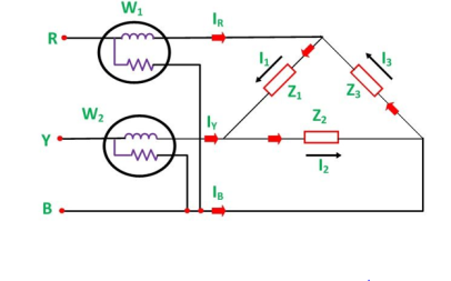
Figure 4. Two Wattmeter by delta
The instantaneous current through the coil of the wattmeter, W1 is given by the equation:
W 1 = i R = i 1 – i 3
Instantaneous power measured by the Wattmeter, W1 will be:
W 1 = e RB
Therefore, the instantaneous power measured by the wattmeter, W1 will be given as:
W 1 = eRB( i 1 – i 3) …………………(3)
The instantaneous current through the current coil of the Wattmeter, W2 is given as:
W2 = i Y = i2 – i1
The instantaneous current through current coil of the Wattmeter W2 is given as :
W 2 = i Y = i 2 – i 1
The instanteneous potential difference across the potential coil of wattmeter, W 2
W2 = e YB
Therefore the instantaneous power measured by Wattmeter W2 will be:
W2 = e YB (i2 – i1 ) ……………………(4)
Hence, to obtain the total power measured by the two wattmeter the two equations, i.e. equation (3) and (4) has to be added.
Where P is the total power absorbed in the three loads at any instant.
W1 + W2 = e RB ( i1 – i3) + e YB ( i2 – i1)
W1 + W2 = i 1 e RB + i 1 e YB – i 3 e RB – i1 e YB
W 1 + W 2 = i 2 e YB + i 3 e BR – i1 ( eYB + e BR) ( that is – e RB = e RB )
W 1 + W 2 = i 1 e RY + i 2 e YB + i 3 e BR
W 1 + W 2 = P
The power measured by the Two Wattmeter at any instant is the instantaneous power absorbed by the three loads connected in three phases. In fact, this power is the average power drawn by the load since the Wattmeter reads the average power because of the inertia of their moving system.
The moving coil instrument works on the principle of the DC motor (electrodynamic effect). It operates by the interaction of the magnetic field produced by a movable coil due to the flow of current with the field of a permanent magnet. It uses a coil for measuring voltage and current.
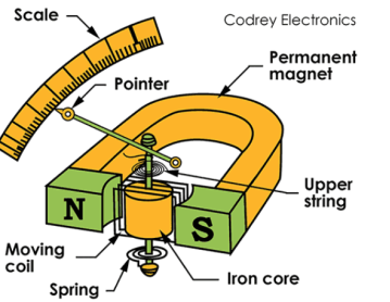
Figure 5. Moving Coil Measuring Instrument
The moving coil meter construction consists of a U-shaped permanent electromagnet. A movable coil of copper wire wounded on a soft iron core and is mounted in the field of a permanent magnet.
The copper coil has many turns and it is pivoted on a jeweled bearing. It can freely rotate in the magnetic field produced by the magnet. Hence these are often known as Permanent magnet type instruments.
The controlling torque is provided by the two control springs (one in lower and other in upper) made of phosphor bronze which is mounted on the jewel bearing and coiled in opposite direction.
A pointer is attached to the spindle which moves over a graduated scale. It has a section over the scale to form a fine blade which helps to reduce error while reading the scale.
Working Principle
The working principle of permanent magnet moving coil type instruments is, When a current being measured is applied to the coil through control springs, it creates a magnetic field. Interaction between this induced field and the field produced by the magnet produces a torque in the coil. This causes the coil to rotate and the pointer deflects on the scale.
The spring is controlled by the spring control method. The damping torque is produced by the eddy current damping.
The deflecting torque in any moving-iron instrument is due to forces on a small piece of magnetically ‘soft’ iron that is magnetized by a coil carrying theoperating current. In repulsion type moving–iron instrument consists of two cylindrical soft iron vanes mounted within a fixed current-carrying coil. One iron vane is held fixed to the coil frame and other is free to rotate, carrying with it the pointer shaft. Two irons lie in the magnetic field produced by the coil that consists of only few turns if the instrument is an ammeter or of many turns if the instrument is a voltmeter.
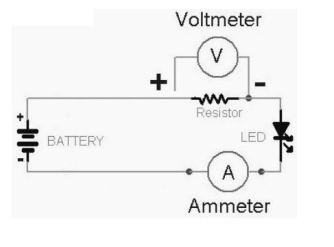
Figure 6. Moving Iron Voltmeter and Ammeter
Current in the coil induces both vanes to become magnetized and repulsion between the similarly magnetized vanes produces a proportional rotation. The deflecting torque is proportional to the square of the current in the coil, making the instrument reading is a true
‘RMS’ quantity Rotation is opposed by a hairspring that produces the restoring torque . Only the fixed coil carries load current, and it is constructed so as to withstand high transient current.
Moving iron instruments having scales that are nonlinear and somewhat crowded in the lower range of calibration.
Ammeter
Voltmeter
3.7 Electrodynamic type wattmeter
Dynamometer type wattmeter works on very simple principle and this principle can be stated as when any current carrying conductor is placed inside a magnetic field, it experiences a mechanical force and due to this mechanical force deflection of conductor takes place.
There are two types of coils present in the electrodynamometer. They are :
Moving Coil
Moving coil moves the pointer with the help of spring control instrument. Limited of current flows through the moving coil to avoid heating. So, in order to limit the current, we have connected the high value resistor in series with the moving coil.
The moving is air cored and is mounted on a pivoted spindle and can move freely. In electrodynamometer type wattmeter, moving coil works as pressure coil. Hence moving coil is connected across the voltage and thus the current flowing through this coil is always proportional to the voltage.
Fixed Coil
The fixed coil is divided into two equal parts and these are connected in series with the load, therefore the load current will flow through these coils. The reason is very obvious of using two fixed coils instead of one, so that it can be constructed to carry considerable amount of electric current. These coils are called the current coils of electrodynamometer type wattmeter.
To derive the expressions for the controlling torque and deflecting torques. In order to derive these expressions let us consider the circuit diagram given below:
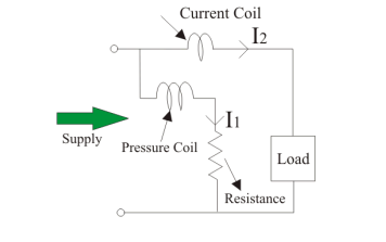
Figure 7. Controlling torque
The instantaneous torque in electrodynamic type instruments is directly proportional to the product of instantaneous values of currents flowing through both the coils and the rate of change of flux linked with the circuit.
Let I1 and I2 be the instantaneous values of currents in pressure and current coils respectively. So the expression for the torque can be written as:
T = I1 x I2 x dM/dx
Where, x is the angle.
Now let the applied value of voltage across the pressure coil be
v =  V sinwt
Assuming the electrical resistance to the pressure coil be very high hence we can neglect reactance with respect to its resistance. In this the impedance is equal to its electrical resistance therefore it is purely resistive.
The expression for instantaneous current can be written as I2 = v / Rp where Rp is the resistance of pressure coil.
I 2 =  x V sin wt / Rp
If there is phase difference between voltage and electric current, then expression for instantaneous current through current coil can be written as
I1 = I(t) =  I sin(wt - ɸ)
As current through the pressure coil is very very small compared to the current through current coil hence current through the current coil can be considered as equal to total load current.
Hence the instantaneous value of torque can be written as
 x V sin wt/ Rp x
  x I x sin(wt - ɸ) x dM/dx
Average value of deflecting torque can be obtained by integrating the instantaneous torque from limit 0 to T, where T is the time period of the cycle.
Td = deflecting torque = VI/Rp cos ɸ x dM/dx
Controlling torque is given by Tc = Kx where K is spring constant and x is final steady state value of deflection.
Single phase induction type energy meter is extensively used to measure energy supplied to a single phase circuit.
Operating principle of Single phase induction type energy meter:
The operation of induction type energy meter depends on the passage of alternating current through two suitably located coils producing rotating magnetic field which interacts with a metallic disc suspended near to the coils and cause the disc to rotate.
The current coil carries the line current and produces field in phase with the line current. The pressure coil is made highly inductive so that the current through it lags behind the supply voltage by 90 degrees. Thus, a phase difference of 90 degrees exists between the fluxes produced by the two coils. This sets up rotating field which interacts with the disc to cause it to rotate.
Construction of Single phase induction type energy meter:
A single phase induction type energy meter generally has:
1. Moving system
2. Operating mechanism
3. Recording mechanism
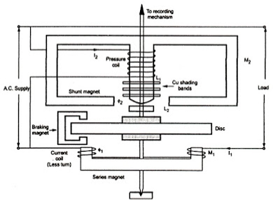
Figure8.Single phase induction type energy meter diagram |
1. Moving system: The moving system consists of a light aluminium disc mounted on a vertical spindle. The spindle is supported by up-shaped jewelled bearings at the bottom end and has a spring journal bearing at the top end.
There is no pointer and control spring so that the disc makes continuous rotation under the action of deflecting torque.
2. Operating mechanism: It consists of series magnet, shunt magnet and breaking magnet.
Series magnet: The series magnet consists of a number of U-shaped laminations assembled together to form a core. A thick wire of few turns is wound on both legs of the U-shaped laminated core. The wound coil is known as current coil and is connected in series with the load so that it carries the load current. The series magnet is placed underside the aluminium disc and produces magnetic field proportional to and in phase with the current.
Shunt Magnet: The shunt magnet consists of a number of M-shaped laminations assembled together to form a core. A fine wire of large turns is wound on the central limb of this magnet.
The wound coil is known as pressure coil and is connected across the load so that it carries current proportional to supply voltage. the shunt magnet is placed above the aluminium disc as shown.
In order to obtain deflecting torque, current in the pressure coil must lag behind the supply voltage by 90 degrees. This necessary phase shift is obtained by placing a copper ring over central limb of shunt magnet.
This copper ring acts as a short- circuited transformer secondary. As its inductance is high as compared with its resistance, the current circulating in the ring will lag by nearly 90 degrees behind the voltage producing it.
Braking magnet: The speed of aluminium disc is controlled to the required value by the C-shaped permanent braking magnet. The magnet is mounted so that the disc revolves in the air gap between the polar extremities.
As the disc rotates, currents are induced in the disc because it cuts the flux produced by the breaking magnet. The direction of the current in the disc is such that it opposes the rotation of the disc.
Since the induced currents in the disc are proportional to the speed of the disc, therefore, breaking torque is proportional to the disc speed.
3. Recording mechanism: The number of revolutions of the disc s a measure of the electrical energy passing through the meter and is recorded on dials which are geared to the shaft.
Working:
When the energy meter is connected in the circuit to measure electrical energy, the current coil carries the load current whereas the pressure coil carries current proportional to the supply voltage.
The magnetic field due to current coil is in phase with line current whereas the magnetic field produced due to pressure coil lags approximately 90 degrees behind the supply voltage.
The current coil field produces eddy currents in the disc which reacts with the field due to the pressure coil. Thus, a driving force is created which causes the disc to rotate.
The braking magnet provides the braking torque on the disc. By altering the position of this magnet, desired speed can be obtained. The spindle is geared to the recording mechanism so that electrical energy consumed in the circuit is directly registered in kWh.
References:
Basic Electrical Engineering Book by Rohit Mehta and V.K. Mehta
Text Book of Electrical Technology Book by B.L. Theraja
Basic Electrical Engineering Book by I.J. Nagrath
Electrical Engineering: Principles and Applications Book by Allan R. Hambley
