Back to Study material
SURVEY

Unit - 5

Construction survey & Modern Techniques such as Space Based Positioning System (SBPS)


  • The main object of the construction survey is as follows:
  • Points and lines are re-established on the ground during construction work
  • Grades are re-established on the ground at the time of construction.
  • It also involves in staking out various details such as bridges and culverts and carrying on the other type of surveying which is more essential during construction.
  • There are some important surveying operations which are being used for the purpose of construction.
  •  

  • Important surveying operations are as follows:
  • Retracing the centre line which is shown on the plan and referencing the certain points on the curves.
  • Checking bench marks (B. M.) and centre line levels are run over the retraced line,
  • Taking elevations at all the station points.
  • Setting slope stakes and grade stakes.
  • Setting stakes for the complete layout of bridges and culverts.
  • Setting out curves.
  • Reporting and making function able changes if any in line or grade or minor adjustments in the drainage structure.
  • Progress Reporting.
  • Final estimate of the object.
  •  


  • Establishing of horizontal and vertical controls play an important role in the procedure of topographical.
  • Establishing Horizontal Control:

  • Horizontal controls involve in location of ground control points. These ground controls points cover the complete area to be surveyed.
  • The boundary of the area to be surveyed can be found out by horizontal control. Horizontal control forms a frame or skeleton of survey of required terrain from which other details and contours can be located.
  • "Working from whole to part" is the fundamental principle of surveying. Excessive error which may be accumulated, can be prevented by following the fundamental principle strictly.
  • For establishing the horizontal control, there are two common methods employed into the surveying work are as follows:
  • Triangulation .
  • Traversing Methods.
  • When the area is small:

  • If the area is small, then only single station is taken in the horizontal control.
  • The other points of the area involved in the boundary can be connected to the single station by measuring relative distance and direction which further forma the triangles.
  • When the area is very large:

  • If the area is very large, then a traverse or series of connected traverses are involved in the horizontal control.
  • Stadia survey is used for an uneven area.
  • When the area is more extensive:

  • If the area is more extensive, then it is feasible to employ the survey into two system of horizontal control.
  • System of horizontal control for large extensive area:

  • Primary control (By triangulation and Precise traversing)
  • Secondary control (By tape traverse or by transit survey or Theodolite traversing)
  • Primary control:

  • Primary control is done by the method of triangulation and precise traversing or only by triangulation. It is not suitable for dense wooded country since triangulation is more expensive and uneconomical.
  • Control points are established on the boundary of the given area in primary control. Then other station within primary control traverse is fixed to form the secondary control with less precision.
  • The degree of accuracy varies from 6√K mm to 10 √K mm according to scale of map. K is a distance in "km'
  • Secondary control:

  • It is done within the primary control. The secondary control stations are established by running transmit survey or tape survey and details can be located.
  • In the Fig., it can be seen that each traverse is started form one primary control station and it is closed on the other primary control station
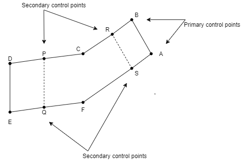
  • Fig.5.1: Primary and Secondary control

  • Note that, sometimes, the secondary control can be done by plane table. P. Q.R.S are secondary control points. For flat and wooded country, for which the method of triangulation is not suitable, the horizontal control is done by precise traversing.
  • The frame work of the terrain or area to be surveyed should cover cach and every portion of the ground.
  • Degree of accuracy varies from 10 √K mm to 204 mm K is a distance in km.
  •  

    Establishing Vertical Control:

  • The method of finding the elevations of various ground features is termed as vertical control. The frame work or skeleton of the area is formed by vertical control.
  • Vertical control is very important because topographical map shows 3D or 3-dimensional relationship or relief of a required area.
  • The main purpose of vertical control is
  • To find the elevations of primary control points
  • To establish bench marks (B. M.) at convenient interval. Bench marks covers the entire area so as to start the levelling operations from starting to end and bench marks also used as reference points for any future work
  • The primary vertical control is done by running high order spirit levelling circuit for the survey having more larger areas
  • The levelling work is possibly done on level or gental slope area
  • The secondary vertical control is established by finding the elevations of traverse station and bench marks near to the station. The secondary vertical control can be done by tacheometric survey or spirit levelling.
  • With the help of levels, the elevation of control station can be found out by running levelling circuits. Note that, it is important to establish the bench mark in such way that bench marks can be observed from nearby horizontal control points
  • Degree of accuracy in case of vertical control varies from 10 √K mm to 20 √K mm in which K distance in km'
  •  

    Key Takeaways:

    1)  Establishing Horizontal Control: Horizontal controls involve in location of ground control points. These ground controls points cover the complete area to be surveyed.

    2)  Establishing Vertical Control: The method of finding the elevations of various ground features is termed as vertical control. The frame work or skeleton of the area is formed by vertical control.


  • The first stage of construction in a site is a setting out of buildings: Setting out consists of outlining the building structure on the ground. For any new housing scheme or extensions or alterations, mapping out is very important so as to avoid the possible costly errors.
  • Following factors which should be considered while laying out the building plans on site-
  • Size of plot,
  • Neighbours,
  • Driveways,
  • Sun direction.
  • Other factors which are required by the local authorities and services on site are as follows:
  • Electricity,
  • Sewers,
  • Water,
  • Communication,
  • Road.
  • When setting of the building is to be done on the ground, the angle with respect to boundary line is considered. The house should be offset from the boundary line by at least 20° to 40° and a building set parallel to the boundary line has a small visual plot size. This offsets also provide good space which can be used in the front and backyards and also make the sun run through the house east to west providing warmful atmosphere in the whole house. For getting maximum sun, set the position of the house north to south.
  • Procedure of setting out of the building is started from a plot corner by putting a peg. Then offset the peg by 4 m at an angle of 20 from the plot end. Length of the building along this angle is then measured and a peg is placed. Then width along 90° from this is marked and completed to the first peg. Then with the four corners in place, map out the area with chalk powder. Use the drawing to locate the extent of the building line with in the mapped area and mark corners.
  • Further, procedure of setting out should proceed by making profile boards. These boards are made of metal or timber which set off the building line. These boards indicate the foundation width and wall thickness. Then strings along this marks is pulled to draw the foundation lines for the whole house. Centre line is then marked for each wall. Squarness is checked and all the dimensions at every intersection is cross checked so as to commence the work.
  •  

    Key Takeaways:

    1)  The first stage of construction in a site is a setting out of buildings: Setting out consists of outlining the building structure on the ground. For any new housing scheme or extensions or alterations, mapping out is very important so as to avoid the possible costly errors.


  • The conventional method to check the verticality of the building is the use of plumb bob. The plumb bob is the most commonly used tool for maintaining verticality of the building.
  • Verticality of the building can be maintained by two plumb bobs at the end of each face of a building, extending upto a fixed height from the base of the tower so that, same reference points are used at all times which give the best result of maintaining verticality of tall buildings.
  • In advanced method, total station can be used for monitoring the northing and easting of the four corners of the building at each level. To do this, four reference pillars or fixed station are to be established on the ground away from the tower from where the corners of the building can be viewed through the telescope of total station till the building reaches its total height.
  • Verticality of tall or high-rise building can also be done by laser beam.
  • The laser plumb can be used for measuring the deviation the transmitter is fixed at the base and the target glass plate is attached to the moving form work. This method is used in the construction of circular silos, chimneys where the slip form method is used for raising the R.C.C tower.
  •  

    Key Takeaways:

    1)  Verticality of the building can be maintained by two plumb bobs at the end of each face of a building, extending upto a fixed height from the base of the tower so that, same reference points are used at all times which give the best result of maintaining verticality of tall buildings.


    After map study engineering or field survey are carried out to finalise the highway alignment.

    The object of thèse surveys is to locate the alignment of a road which provides maximum transportation facilities with minimum cost of construction and maintenance.

    For locating a highway, the following engineering or field survey are undertaken.

  • Reconnaissance survey,
  • Preliminary survey,
  • Location survey.
  • Reconnaissance survey:

  • A field survey party examines the general character of a fairly broad stretch of land between the terminal stations in the field, along the proposed alternative alignments marked on the map is known as reconnaissance survey.
  • In this survey, simple survey instruments like prismatic compass, abney level, tangent clinometer, barometer etc. may be used to collect additional details rapidly.
  • Objects:
  • To collect the details of obstruction along the route which are not available in the map. For example, valleys, ponds, lakes, marshy land, ridge, hills, permanent structure etc.
  • To collect geological features of field. For example, soil type along routes from field identification tests and observation required for the foundation work of bridges of road pavements.
  • To collect information regarding the availability of local construction material, water and labour.
  • To determine the approximate values of gradient, length of gradients and radius of curves of alternate alignments.
  • To locate the obligatory points along the alternative routes.
  • To determine approximate estimate of the total cost of construction of the road along each route.
  • To determine two or three best possible routes.
  • Preliminary survey:

  • Defination: The art of finding the details of alternative alignments found suitable during the reconnaissance survey is known as preliminary survey.
  • In preliminary survey, the survey instruments to be used are chain tape, prismatic compass, levelling instrument, plane table, theodolite.
  • Objects:

  • To survey along the various alignments found after the reconnaissance and to collect all necessary physical information and details of topography. drainage and soil.
  • To compare the different proposals in view of the requirements of a good road alignment.
  • To estimate the cost of constructing the road including bridges and other construction aspects along each alternative alignment of the road.
  • To finalise the best alignment from construction, maintenance and traffic operation point of view.
  • Location survey:

  • Defination: The detailed examination of the field along the alignment finally recommended during the preliminary survey is called location survey.
  • In this survey instruments used are theodolite, level, plane table, tape etc.
  • Objects:

  • The alignment finalized at the design office after the preliminary survey is to be first located on the field by establishing the center line
  • The detailed survey should be carried out for collecting the information necessary for the preparation of plans and construction details for the highway project.
  • To determine total cost of the road project.
  •  

    Key Takeaways:

    For locating a highway, the following engineering or field survey are undertaken.

  • Reconnaissance survey
  • Preliminary survey
  • Location survey
  •  


  • The starting off of a culvert is pretty easy due to the fact there's simplest one span and the go with the drift of water is less.
  • Even if the go with the drift of water is more, it is able to be without problems diverted.
  • But withinside the case of Bridges and dams, the go with the drift of water can't be diverted and additionally the duration can be very long.
  • Therefore, starting off isn't feasible from the centre of the bridge.
  • The starting off entails the subsequent operations:
  • Preparation of topographic map of the bridge site.
  • Determination of the duration of the bridge.
  • Location of piers.
  •  

    Key Takeaways:

    1)  Setting out of bridge consist of following points:

    a)  Preparation of topographic map of the bridge site.

    b) Determination of the duration of the bridge.

    c)  Location of piers.


    There are two methods for locating piers for a bridge:

    Two methods for locating plers for a bridge-

  • By finding the length of the centre line of the bridge accurately.
  • By locating the central point for each pier.
  •  

    1. By finding the length of the centre line of the bridge

  • Centre line is the distance between two points of the two opposite banks of a river. These two points lies on the centre line of a road or railway.
  • The length of the centre line of a small or short bridge can be measured directly by means of steel tape.
  • The procedure for measuring the length is same to as it is followed in measuring the length of a base line of tertiary triangulation.
  • For long bridge, the length is generally determined by the method of triangulation.
  • There are four methods for locating piers for a bridge. Out of these four methods, the important methods are explained as follows.
  • Method I

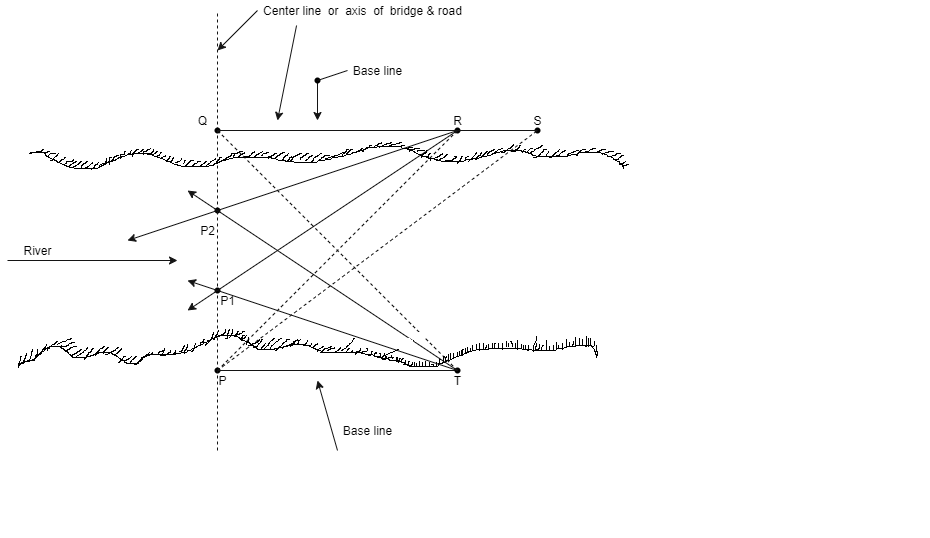
    Fig.5.2: Locating piers for bridge by method 1

  • In method I, P and Q are the two points located on opposite banks of a river on the centre line of the road. PR is the base line which is exactly perpendicular to the centre line or axis PQ of the bridge. In this case, the base line PR and angle PRQ are carefully and accurately measured. Note that for better accuracy; ZPRQ is measured by the method of six repetition. Six repletion means three repetitions with the telescope direct and three with telescope reversed.
  • 1 (PQ) = PR tan

  • Another base line PS is laid on the same bank but on upstream side because there is no cheek on the first work.
  • Then length PQ is determined from the measured length PS and the measured angle PSQ. Then mean of these two values of length PQ is taken as the true values of PQ.
  • Now PQ is the centre-line or axis of the bridge PT and QR are the base lines and P, and P2 are the central points of piers. The base lines are measured precisely with a steel tape in a same way to that used in the measurement of base line in tertiary triangulation. Angles PQR and PQT are accurately measured by the method of three repetition with a transit reading to 20" or 10".
  • Note that length PQ is determined from A PQR and also from PQT, should tally within the allowable limit of error of Icm per 200m and the mean of these two values is taken as the most probable value of the length of the axis or centre line of the bridge.
  • Method II

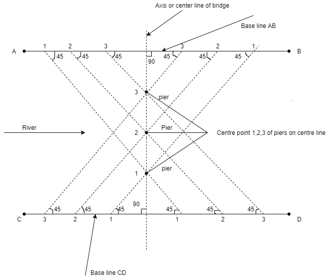
    Fig.5.3: Locating piers for a bridge by method 2

  • In method II, a base line is fixed on each bank exactly at right angles to the centre line or axis of the bridge. Refer to the Fig. for better understanding.
  • The length of the centre line PQ is determined by method of triangulation and then the positions of centre points say 1 and 2 of piers on the centre line as shown in Fig. is determined.
  • The stepwise procedure of locating the piers is as given below:
  • The base line is laid on each bank at right angle to the axis of bridge and then set off on each base line and on each side of the centre line, the distances to the 1 and 2 (i.e., centre points) from the base line as shown in Fig. This gives two intersecting lines 1-1, 2-2, and 3-3 etc. which makes angles of 45° with respect to base line already established on opposite banks of river and also with respect to centre line of the bridge.
  • Then centre point 1 is located by sighting simultaneously, at the intersection of two intersecting lines 1-1. In same manner centre points 2 and 3 are located at the intersection of two it intersecting lines 2-2 and 3-3.
  • Advantage and disadvantage of this method-

  • This method does not require to turn off an angle to establish any one of the intersecting lines, but these lines can be established by simply sighting from a point on one bank to the corresponding point on the opposite bank.
  • It is an ideal method but not commonly used into the practice because it depends upon favourable conditions for laying out the base lines exactly perpendicular to the axis or centre line of the bridge.
  • Method III

  • In this method, two base lines are established on opposite banks either both on upstream or both downstream. These two base lines are approximately at right angles to the axis or centre line of the bridge.
  • The lengths of the base lines should not be less that 3/4th or three quarters of the length of the bridge and these base lines should be approximately equal to the length.
  • In this method, no need to establish the base lines exactly at right angles to centre-line of bridge but under most favourable conditions, it is roughly at right angles to the centre-line of bridge.
  • Method IV

  • Whenever more accuracy and precise work is required, then fourth method is generally used in which the use of a geodetic quadrilateral PQRS as shown in Fig. is preferably done.
  • H:\unit 5 survey\IMG_20210528_103618.jpg

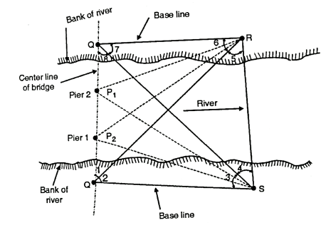
    Fig.5.4: Locating piers for a bridge by method 4

  • In quadrilateral PQRS, eight angles are carefully measured with a theodolite of 10" accuracy by the method of repetition. The base lines PS and QR are then measured. The length of the base line QR is calculated from the corrected length of PS and adjusted values of the angles and these values are then compared with the measured values of PS and QR.
  • Note that, the error between the two values should not less than 1 in 5000. After satisfying the check, the calculated value of length PQ is sufficiently accurate.
  •  

    2. By locating the central point for each pier

  • From the ends of a base line, the central points of the piers are located by intersection of sights being taken simultaneously.
  • From the calculated length of centre-line 'PQ' of the bridge and fixed positions of the central points P, and P2 of the piers as shown in Fig.on the plan drawn, the angles PSP, PSP2, QRP, QRP are computed with the know lengths PS, PP, PP, and QP, and QR and with known angles QPS and PQR.
  • Transits are set up over the station P and S so as to locate the point P. Then instrument at P is directed to 'S' and angle PSP, is turned off at 'S' and P is established by simultaneous sighting.
  • The intersection of the line-of-sight PS, and line of sight 'PQ' along centre-line gives the location of point P.
  • To obtain the check of location of P, the instrument is set up over station 'R' and the angle QRP, is set off and the line-of-sight RP, should pass almost exactly through P. In same manner, point P, is located.
  •  

    Key Takeaways:

    1)  Two methods for locating piers for a bridge:

    a)  By finding the length of the centre line of the bridge accurately.

    b) By locating the central point for each pier.


    Definition: The process of setting out the alignment of the tunnel on the ground and then transferring the same to inside of the tunnel through shafts is called tunnel surveying.

    The survey work of a tunnel involves the following operations:

  • Locating centre line of the tunnel on ground.
  • Constructing the shafts over the centre line.
  • Transferring the alignment to inside of the tunnel.
  •  

    Locating centre line of the tunnel on ground:

  • After fixing the route for the tunnel, its centre line (alignment) is accurately set out on the hills or ground.
  • When the length of tunnel is small, the centre line can be located by means of theodolite.
  • When the tunnel is long, and to be constructed under high mountains, the centre line is set out by triangulation preferably with the help of a micrometer transit theodolite.
  • In the ground, pegs are driven at regular intervals and centre line is marked.
  • If it is not possible to drive pegs into the ground, the surface of the rock pointed white and centre line is marked with black paint on it.
  • The alignment is then finally set out by permanent monuments of stone or concrete.
  • Constructing the shaft over the centre line:

  • After locating centre line, shafts are constructed at regular interval.
  • Transferring the alignment to inside of the tunnel:

  • After constructing the shafts, the alignment of the tunnel is to be transferred down the shafts.
  • For this, two small pillars are constructed on opposite edges of the shaft along the centre line of the tunnel.
  • On the top of these pillars, the points corresponding to the centre line are correctly marked and wire is then stretched between them.
  • Two plumb bobs are suspended inside the shaft as shown in above figure. By lowering both plumb- bobs to the bottom of the shaft, two points are marked.
  • The line joining the points represents the centre line of the tunnel marked on the ground.
  • This line is further extended into the tunnel, as work advances, by a theodolilte placed in the shafts as shown in Fig.
  • H:\unit 5 survey\IMG_20210528_103634.jpg

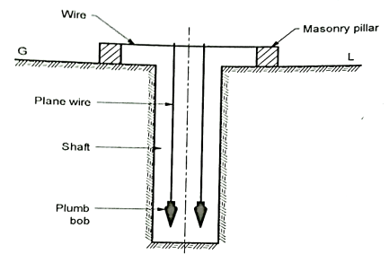
    Fig.5.5: Transferring the alignment at the bottom of the shaft


    H:\unit 5 survey\IMG_20210528_103651.jpg

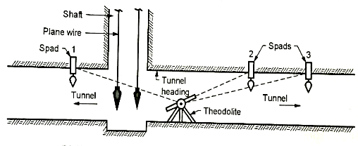
    Fig.5.6: Transferring the alignment to inside of the tunnel


    Key Takeaways:

    1)  The survey work of a tunnel involves the following operations:

    a)  Locating centre line of the tunnel on ground.

    b) Constructing the shafts over the centre line.

    c)  Transferring the alignment to inside of the tunnel.


  • When we are setting out tunnel centre line on surface, generally surface control points that is the portal points or the points at which tunnel starts and ends are not visible from each other.
  • In short and/or straight tunnels or tunnels under plane ground, the centre line may be accurately located by the process of instrumental ranging and prolonging a line with help of a common theodolite, on a clear day with a linear accuracy of 1:10000 and angular closing error not exceeding [15 √N].
  • In long tunnels or tunnels in hilly regions, it is neither possible to align the tunnel from end by any kind of ranging, precise triangulation has to be resorted to in such cases.
  • The points set out on surface may be marked temporarily with wooden stakes. These wooden stakes shall be replaced with stone or concrete blocks after checking and rechecking
  •  


  • Position of any object on the surface of the earth can be determined by spaced based positioning system (SBPS). SBPS receivers determine the position of any object existing on the surface of the Earth by trilateration of microwave signals from satellite moving in the orbit of the earth at an altitude of 20200 km.
  • Tracks of a journey can automatically be recorded into the GPS receiver’s memory and can sub sequentially be downloaded onto the computer as a basis for drawing. sculpture or animation. Note that this track of journey may be on the surface (e.g., walking) or taken in three dimensions (3D) (e. g. while flying).
  • It is important to note that the SBPS is the only fully functional global navigation satellite system. The satellites moving in orbits transmit precise microwave signals and the system enables a SBPS receiver so as to determine its location, speed, direction and time.
  • SBPS is now-a-days used in navigation worldwide and it is very useful tool for map-making, land surveying, commerce and scientific uses. GPS also provides a precise time reference used in many applications including scientific study of earthquakes and synchronization of telecommunication networks.
  • Definition of SBPS: Spaced based positioning system (SBPS) technology is a fast and accurate method of determining the location of any point of interest anywhere on the face of earth of any time during the day or night.
  • The technology collects and processes signals from satellites in orbit around the earth to determine the location of points of interest on the ground.
  •  

    Key Takeaways:

    1)  Spaced based positioning system (SBPS) technology is a fast and accurate method of determining the location of any point of interest anywhere on the face of earth of any time during the day or night.


    Working System of GPS with SBPS:

  • The basic principles of GPS are very simple. The GPS works on five fundamental concepts. These concepts are as follows.
  • This system is based on Triangulation from satellites.
  • For Triangulation, the GPS receivers measure the distance, for which the travel time of the radio message from the satellite is used.
  • It needs to use a very high precision clocks, to measure the travel time (to measure the distance
  • After the measurement of the distance the location of the satellite becomes important.
  • There is a time lag as the GPS signals travel through the ionosphere (upper layer of the atmosphere above the stratosphere layer) from transmitting the signal by satellite and receiving the same by the receiver.
  • Types of GPS:

    There are the basic types of survey grade systems in GPS.

  • Single Frequency.
  • Dual Frequency.
  • Single Frequency:

    This type of surveying with a single frequency system is called as 'static mode' GPS surveying.

    Dual Frequency:

    Dual frequency systems only require post processing when operating in static or fast static.


  • Glonass is Russian global Navigation satellite system, was a fully functional navigation constenation in 1995.
  • After the collapse of the Soviet Union, it fell into disrepair, leading to gaps in coverage and only partial availability. It has recovered and full operational and restored in 2011.
  •  


  • The European Union and European Space Agency agreed in March 2002 to introduce their own alternative to SBPS-GPS known as Galileo positioning system.
  • The system of 30 medium Earth Orbit Satellites was originally scheduled to be operational in 2010. Galileo is expected to be compatible with advanced and modernised SBPS-GPS system.
  • The receivers can able to combine the signals from both Galileo and GPS satellites to greatly increase the accuracy. Note that Galileo is now not expected to be in full service until 2020 at the earliest and at a higher cost.
  •  


  • GAGAN system is an Indian Satellite Based Navigation Augmentation system. The GAGAN provides a civil aeronautical navigation signal consistent with international Civil Aviation Organisation (ICAO).
  • GAGAN system is jointly developed by Indian Space Research Organisation (ISRO) and Airports Standards and Recommended Practices (SARPS) as established by the GNSS Panel (i.e., Global Navigation Space System)
  • GAGAN implementation is carried out in two phases viz:
  • Phase I: Technology Demonstration System (TDS) phase which has the objective to demonstrate the feasibility of Space Based Augmentation System (SBAS).
  • Phase II: Final Operational Phase (FOP): This phase is used for providing a certified satellite-based navigation system for all phases of flight by augmenting the TDS system suitably
  • Fig. shows GAGAN satellite configuration and required ground infrastructure for final operational phase (FOP)
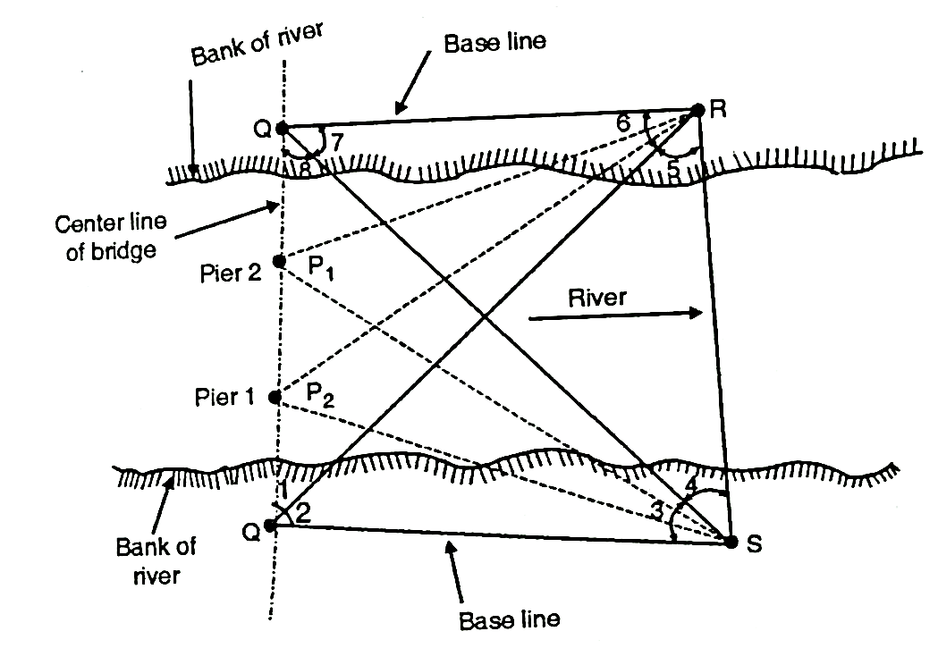
  • Fig.5.7: Configuration of GAGAN Satellite


    Key Takeaways:

    1)  GAGAN system is jointly developed by Indian Space Research Organisation (ISRO) and Airports Standards and Recommended Practices (SARPS) as established by the GNSS Panel (i.e., Global Navigation Space System).


  • China fielded a demonstration regional satellite-based navigation system named as BeiDou. The initial regional BeiDou System (i.e., BeiDou 1) has been replaced by a global system named as BeiDou 2 (or simply BeiDou) and formly known as compass.
  • Compass include five GEO-Satellites; 2.7 medium earth orbit MEO) satellites, and five inclined geosynchronous orbit ((IGSO) satellite. BeiDou - 2, formerly name as Compass was declared operational for use in China and surrounding areas on December 27, 2011.
  •  


    H:\unit 5 survey\IMG_20210528_103725.jpg

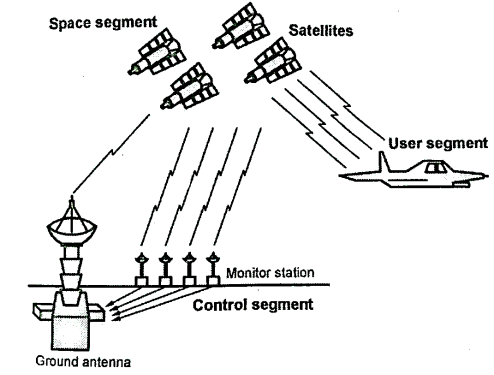
    Fig.5.8: System segmentation

    Space Segment (SS):

  • It is an important segment since it comprises the orbiting GPS satellites or space vehicles (SV) in GPS parlance. The GPS design originally called for 24 space vehicles, eight each in three circular orbital planes. However, it is modified to six planes with four satellites each.
  • The orbital planes are centered on the Earth and these planes are not rotating with respect to the distinct stars. The six planes have an inclination of 55° approximately with respect to Earth's equator and these planes are separated by 60° right ascension of the ascending node. 60° right ascension means the angle along the equator from a reference points to the intersection of the orbit. These orbits are arranged in such way that at least six satellites always remain within the line of sight from almost everywhere on the surface of earth.
  • Satellites are orbiting at an altitude of 20200 km approximately with the orbital radius of 26600 km. Each satellite vehicles performs two complete orbits on each sidereal day and hence the ground track of each satellite repeats each sidereal day.
  • The ground track repeat can be used the ensure good coverage in combat zones.
  • Fig. shows the details of space segment.
  • H:\unit 5 survey\IMG_20210528_103741.jpg

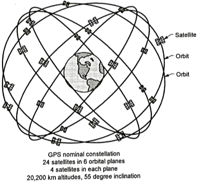
    Fig5. 9: Details of Space segment

    Control Segment

  • The track of satellite is well decided and the flight paths of the satellite are tracked by US air force monitoring the stations in Hawaii, Kwajalein, Ascension Island, Diego Garcia and Colorado Springs, Colorado along the monitor stations operated by the National Geospatial Intelligence Agency (NGA).
  • The tracking information is sent to the air force space command's master control station at Schriever air force base in Colorado Springs which is further operated by the two-dimensional (2d) space operations squadron of the united state Air force. Two space operations squadron contacts each GPS satellite regularly with a navigational update by using antennas.
  • These updates synchronize the atomic clocks on the board of satellites within a few nanoseconds of each other and adjust the ephemeris of each internal model of each satellite.
  • The updates are produced by Kalman filter which uses inputs from the ground monitoring stations, space weather and information and also the various other inputs.
  • User Segment

  • This is the segment in which GPS receivers are made of an antenna tuned to the frequencies transmitted by the satellite’s receiver-processors and a highly-stable clock.
  • It also provides location and speed information on display to the user. The number of channels signifies how may satellite the receiver can monitor simultaneously.
  • Importance and Role of Space Segment, Control Segment and user Segment in SBPS:

    Space segment

  • It generates and transmit code, carrier phases and navigation message.
  • Here input is navigation message and output are P code C/A code, L1 and L2 which carries navigation message.
  • Control segment

  • It produces GPS time.
  • It predicts ephemeris
  • It manages space vehicle
  • Here input is P code observation and time and output is navigational message. It works out satellite orbit and clock parameter and passes the results to ground antennas.
  • User’s segment

  • It gives the navigation solution.
  • It also gives the surveying solution.
  • Here input is code observation, carrier phase observation and navigation message and output are position, velocity and time corrections such as delay due to ionospheric and tropospheric refraction clock errors etc are also computed and applied by users’ segment i.e., by user’s equipment or processing software.
  •  

    Key Takeaways:

    1)  There are three types of segments:

    a)  Space segment.

    b) Control segment.

    c)  User segment.


  • Determining the boarders, making existing utilities like highway, municipal amenities photogrammetric and private site-specific projects make them more dense or compact.
  • GIS data acquisition.
  • Monitoring, well, soil bring and other types of sampling locations.
  • Establishing state plane coordinate or geodetic coordinates.
  • Used in 'As-built Survey and Topographic survey.
  • Used for mine exploration.
  • Used in Baseline survey and traverse control survey or traverse verification surveys.
  • Used in natural resource mapping.
  • Used in communication tower survey and certifications.
  • Used in construction stakes out utilities, highways, facilities, pilling etc.
  •  

    References:

  • Surveying and leveling by r. Subramanian, Oxford Publication.
  • GPS Satellite Surveying-Alfred Leick-Wiley.
  • Surveying and leveling Vol.1 and 2 by T.P. Kanetkar and S.V. Kulkarni Pune vidyarthi Griha Prakashan.
  • Surveying by B.C. Punmia.
  •  


    Index
    Notes
    Highlighted
    Underlined
    :
    Browse by Topics
    :
    Notes
    Highlighted
    Underlined