UNIT-3
Higher order Elements
For the analysis of structure problem of complex shape involving curved boundaries or surfaces, simple triangular or rectangular elements are no longer sufficient.
This has led to the development of the elements of more arbitory shapes known “isoparametric elements “
3.1.1 Isoparametric elements-
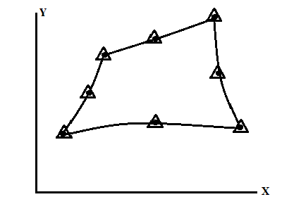
If the same number of elements are used to defined geometry as well as displacement the element is called isoparametric elements
E.g.
X= N1x1 + N2 x2 +…………………….+N8x8
(Geometry)
y= N1y1 + N2 y2 +…………………….+N8y8
u= N1u1 + N2 u2 +…………………….+N8u8
(displacements)
v= N1v1 + N2 v2 +…………………….+N8v8
|
Fig.1.Isoparametric elements
|
3.1.2 Sub parametric elements –
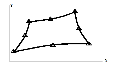
The elements in which less number of nodes is used to defined geometry compare to the number of nodes used to defined displacement, the element is called sub parametric elements.
E.g.
X= N1x1 + N2 x2 +N3x3 + N4x4
(Geometry)
y= N1y1 + N2 y2 +N3y3 + N4x4
u= N1u1 + N2 u2 +…………………….+N8u8
(displacements)
v= N1v1 + N2 v2 +…………………….+N8v8
|
Fig.2.Sub parametric elements
|
3.1.3 Super parametric elements –
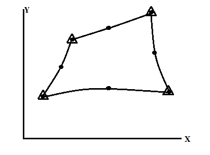
The elements in which less number of nodes is used to defined displacement compare to the number of nodes used to definedgeometry, the element is called super parametric elements.
E.g.
X= N1x1 + N2 x2 +…………………….+N8x8
(Geometry)
y= N1y1 + N2 y2 +…………………….+N8y8
u= N1u1 + N2 u2 +N3u3+N4u4
(displacements)
v= N1v1 + N2 v2 +N3v3++N4v4
|
Fig. 3. super parametric elements
|
Key Takeaways:
1) If the same number of elements are used to defined geometry as well as displacement the element is called isoparametric elements.
2) The elements in which less number of nodes is used to defined geometry compare to the number of nodes used to defined displacement, the element is called sub parametric elements.
3) The elements in which less number of nodes is used to defined displacement compare to the number of nodes used to definedgeometry, the element is called super parametric elements
- In the Finite Element Method, an element's Jacobin Matrix relates the quantities wrote in the natural coordinate space and the real space.
- The bigger the element is distorted in comparison with an ideal shape element; the worse will be the transformation of the quantities from the natural space to the real space.
- In fact, it means that the distortion on the element shape will introduce error in the mathematical transformation from natural space to the real space.
- In a FE Software, the Jacobin (also called Jacobin Ratio) is a measure of the deviation of a given element from an ideally shaped element. The Jacobin value ranges from -1.0 to 1.0, where 1.0 represents a perfectly shaped element. The ideal shape for an element depends on the element type.
- The check is performed by mapping an ideal element in parametric coordinates onto the actual element defined in global coordinates.
- For example, the coordinates of the corners of an ideal quad element in parametric coordinates are (-1,-1), (1,-1), (1,1), and (-1,1). The determinant of the Jacobin relates the local stretching of the parametric space required to fit it onto global coordinate space.
- The picture attached illustrates a real QUAD4 element, frequently found in a mesh, and the ideal QUAD4 element.
- An element's Jacobin Matrix is a square matrix which have dimension of 1x1 for 1D element, 2x2 2D elements and 3x3 for 3D elements. The terms inside this matrix are functions that depend on the parametric coordinates "r", "s" and "t" in most cases.
- Therefore, the determinant of an element's Jacobin Matrix will depend on which points the FE package will use in the calculation.
- Many software (Hyper Mesh, for example) evaluates the determinant of the Jacobin Matrix at each of the element's integration points (also called Gauss points). For example, one element which has 4 integration points will have 4 values of determinant.
- The Jacobin in the Finite Element vocabulary is defined as the ratio between the smallest and the largest value of the Jacobin Matrix determinant. Therefore, the Jacobin is always between 0 and 1.
Key Takeaways-
1) In a FE Software, the Jacobin (also called Jacobin Ratio) is a measure of the deviation of a given element from an ideally shaped element. The Jacobin value ranges from -1.0 to 1.0, where 1.0 represents a perfectly shaped element. The ideal shape for an element depends on the element type.
2) The Jacobin in the Finite Element vocabulary is defined as the ratio between the smallest and the largest value of the Jacobin Matrix determinant. Therefore, the Jacobin is always between 0 and 1.
3.3.1 One Dimensional (1-D)
Some principles of numerical integration will be summarized here together with tables of convenient numerical coefficients. To find numerically the integral of a function of one variable we can proceed in one of several ways as discussed next.
- Newton–Cotes quadrature
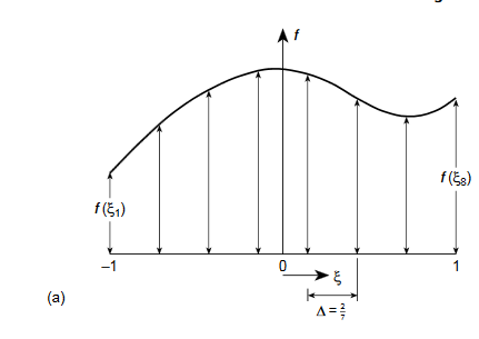
In the most obvious procedure, points at which the function is to be found are determined priori– usually at equal intervals – and a polynomial passed through the values of the function at these points and exactly integrated.
As n values of the function define a polynomial of degree n−1, the errors will be of the order ( ) where h is the element size. The well-known Newton–Cotes ‘quadrature ‘formulae can be written as
|
For the range of integration between−1 and+1 .
For example,
if n=2, we have the well-known trapezoidal rule:
I=f (−1) +f (1)
For n=3, the Simpson ‘one-third’ rule:
I=1/3[f (−1) +4f (0) +f (1)]
And for n=4:
I=1/4[f (−1) +3f (−1/3) +3f (1/3) +f (1)]
|
Fig 4.Newton–Cotes quadrature
II. Gauss quadrature-
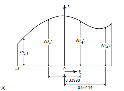
If in place of specifying the position of sampling points priories allow these to be located at points to be determined so as to aim for best accuracy, then for a given number of sampling points increased accuracy can be obtained. Indeed, if we again consider
|
And again assume a polynomial expression, it is easy to see that for sampling points we have 2nunknowns (w i andξi) and hence a polynomial of degree 2n−1 could be constructed and exactly integrated. The error is thus of order ( ).
).
|
Fig.5.Gauss quadrature
Gaussian location and weights-
Number of points ,n | Points | Weights |
1 | 0 | 2 |
2 |
|
1 |
3 |
0 |
|
|
|
3.3.2 Numerical integration – rectangular (2D) or brick regions (3D)
The most obvious way of obtaining the integral
is first to evaluate the inner integral keeping
Evaluating the outer integral in a similar manner, we have
|
Key Takeaways-
(1) The well-known Newton–Cotes ‘quadrature ‘formulae can be written as
(2) The range of integration is always between−1 and+1 .
|
Question 1) Evaluate the following integral
|
Ans:-
Step 1
To find the point of Gaussian Quadrature
2n-1 = Higher order
From given equation, Higher order = 4
2n-1 = 4
N=2.5
N~3 (Three point Quadrature problem)
Step 2 To find qaussian location and weights
Number of Points, n | Points, x1 | Weights, w1 | x1 = 0 x2 = + x3 = - w1’ 8/9’0.8888 w2’5/9’0.5555 w3’5/9’0.5555 |
1 | 0 | 2 | |
2 | ± | 1 | |
3 | 0 |
| |
± |
|
Step 3 Find Au f(x) values
F(x)’(x4 – 3x + 7) dx
F(x1) = x14 – 3x1 + 7 = 7
F(x2) = x24 – 3(x2 )+ 7 = 5.0362
F(x3) = x34 – 3(x3 )+ 7 = 9.6837
Step 4 Evaluate using single integral formula
→ w2 f(x1) + w2 f(x2) +w3 f(x3) = (0.8888 × 7) + (0.5555 × 5.0362) + (0.5555 × 9.6837)
|
Question 2 Evaluate the following integral
|
Soln:-
Step 1- To find the point of gaussian Quadrature
2n-1 = Higher order = 2
n= 1.5
n~2 (Two point Quadrature problem)
Step 2 To find gaussian location and weights
Number of points,n | Points, x1 | Weights, w1 |
1 | 0 | 2 |
2 | ± | 1 |
3 | 0 | 8/9 |
± | 5/9 |
Since it is double unequal, we have to take both x & y.
x1 = + x2 = -
|
Step 3 All f(x) values here, substitute values of x1, x2, y1 & y2
F(x, y) = (2x2 + 3xy + 4y2)
F(x1, y1) = (2x1 2 + 3x1y1 + 4y12) = 3
F(x1, y2) = (2x1 2 + 3x1y2 + 4y22) = 1
F(x2, y1) = (2x2 2 + 3x2y1 + 4y12) = 1
F(x2, y2) = (2x2 2 + 3x2y2 + 4y22) = 3
Step 4 Evaluate using double integral formula
Substitute w1, w2 and all f(x) values in above equation = (1×1×3)+(1×1×1)+(1×1×1)+(1×1×3)
|
- Mesh generation has always been a time-consuming and error-prone process. This is especially true in the practical science and engineering computations, where meshes have to be generated for three-dimensional geometries of various levels of complexity.
- The automatic mesh generation process has been an active research subject since the early 1970s.
- Before proceeding further on mesh generation schemes it is necessary to specify the kind of mesh we desire. Here we should give the following information:
- The type of element and the number of nodes required on each
- The size of the desired element, here the minimum size of each element generally is specified;
- Specification of regions of different material types or characteristics to be attached to a given element; and
- In some cases, the so-called stretch ratio if we wish to present elements which are elongated in some preferential direction
3.5.1 The mesh generation procedure includes three main steps:
- Node generation along boundary edges to form a discretized boundary of the domain.
- Element (and node) generation within the discretized boundary.
- Element shape enhancement to improve the quality of the mesh.
3.5.2 Geometrical characteristics of the mesh
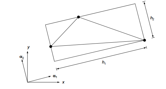
- The geometrical characteristics of the mesh such as element size, element shape and element orientation are represented by means of mesh parameters which are spatial functions.
- The mesh parameters include two orthogonal directions defined by unit vectorsαi(i=1,2)and the associated element sizes hi(i=1,2)as illustrated in Fig.
- The orthogonal directionsαi (i=1, 2) describe the directions of element stretching. A mesh with stretched elements in certain directions is only necessary when a non-isotropic mesh is desired, otherwise thestretching directions are set to be constant unit vectors in the coordinate directions and the related element sizes are set to be equal, i.e.,h1=h2. In this case, the generated elements will not be stretched in any direction and an isotropic mesh type will be generated.
|
Fig.6. Mesh parameter in two dimensions
Key Takeaways-
(1)The mesh generation procedure includes three main steps:
- Node generation along boundary edges to form a discretized boundary of the domain.
- Element (and node) generation within the discretized boundary.
- Element shape enhancement to improve the quality of the mesh.
(2) The geometrical characteristics of the mesh such as element size, element shape and element orientation are represented by means of mesh parameters which are spatial functions.
References-
(1) Finite Element Analysis -C.S. Krishnanmoorthy, Tata McGraw Hill Publishing Co. Ltd, New Delhi,
(2) The Finite Element method -ZIENKIEWICZ.O.C.Tata McGraw Hill Pub. New Delhi, 2000
(3) Finite Element Methods by C R Alaval , PHI
(4) Finite Elements in Engineering:- Chandrupatta, et. AI. Prentice Hall of India Pvt. Ltd.,
