Unit-5
Analysis of structures
- Definition: A truss is a structure that consists of
1) All straight members
2) Connected together with pin joints
3) Connected only at the ends of the members
4) And all external forces (loads & reactions) must be applied only at the joints.
- The analysis of trusses is usually based on the following simplifying assumptions:
1) The centroidal axis of each member coincides with the line connecting the centers of the adjacent members and the members only carry axial force.
2) All members are connected only at their ends by frictionless hinges in plane trusses.
- Trusses Using FEA In this section, we will apply basic finite element techniques to solve general two dimensional truss problems. The technique is a little more complex than that originally used to solve truss problems, but it allows us to solve problems involving statically indeterminate structures.
Stiffness matrix of a truss element
- The truss may be statically determinate or indeterminate. All members are subjected to only direct stresses (tensile or compressive). Joint displacements are selected as unknown variables.
- Since there is no bending of the members we have to ensure only displacement continuity (C continuity) and there is no need to worry about slope continuity (C continuity).
- Here we select two noded bar element for the formulation of stiffness matrix of truss element. Since the members are subjected to only axial forces, the displacements are only in the axial directions of the members.
- Therefore, the nodal displacement vector for the bar element is
{ Where, [
|
Problems-
Example 1-
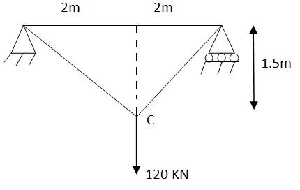
Analyze the truss as shown in fig. cross sectional area of members are AB= 1000  , BC=800
 ,CA= 800
 take E
|
Fig.1
Ans-
|
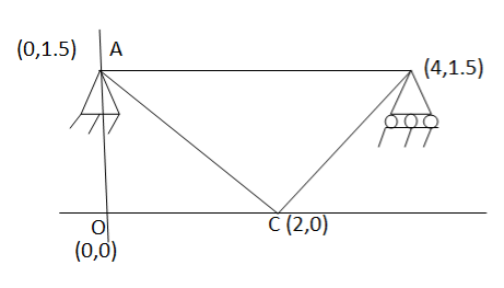
Fig.2
Step-1 degrees of freedom Discretization –
Assume x-axis horizontal through point (& vertical through point A). the co-ordinates of node A(0,1.5) , B(4,1.5) & C(2,0) . take E in Gpa.
Step-2 element stiffness matrices Stiffness matrix of element AB .
Stiffness matrix of element BC
Stiffness matrix of element CA
Step 3- global stiffness matrix Total Dof are 06, size of stiffness matrix 6*6
Step -4 reduced stiffness matrix Since
Step -5 equation of equilibrium
|
Example -2
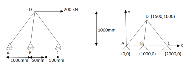
Figure shows a plane , truss with three members cross- sectional area of all members 500 young modulus is 200 KN/
 . Determine deflection at loaded joint .
|
Solution –
Step 1 – degree of freedom ;- Discretization
Assume origin support A(0,0). The co-ordinates of other nodes& B(1000,0), C(2000,0) and D(1500,1000)
Step -2 element stiffness matrices Stiffness matrix of element AD
Step – 4 equations of equilibrium
|
Example 3 –
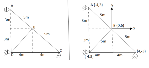
For the truss as shown in fig. using finite element method, determines deflections at loaded joints. The joint B is subjected to 50 KN horizontal force towards left & 80 KN force vertically downward. take cross sectional area of all the members 1000 young modulus is 200 Gpa.
|
Fig.4
Ans-
Step -1 degree of freedom (06) Discretization
Assume origin point B. the co-ordinates points are
Step -2 stiffness matrix of element AB .
Stiffness matrix at element DB.
Step 3- reduced stiffness matrix
Step 4- equation of equilibrium
|
Steps for the solution of Indeterminate plane frames using finite element method:
1. Divide the frame into number of elements (Take one member as one element)
2. Identify total degrees of freedom (Three D.O.F. at each node, two displacements and rotation)
3. Determine stiffness matrices of all elements ([K]1, [K]2……)
4. Assemble the global stiffness matrix [K]
5. Impose the boundary conditions and determine reduced stiffness matrix.
6. Determine element nodal load vector [q] (Restrained structure)
7. Determine equivalent load vector[f]
8. Apply equation of equilibrium [K]{∆}={f}, and determine unknown joint displacements.
9. Apply equation [K]{∆}+[q]={f} to determine reactions and moments
Problems-
Example 1-
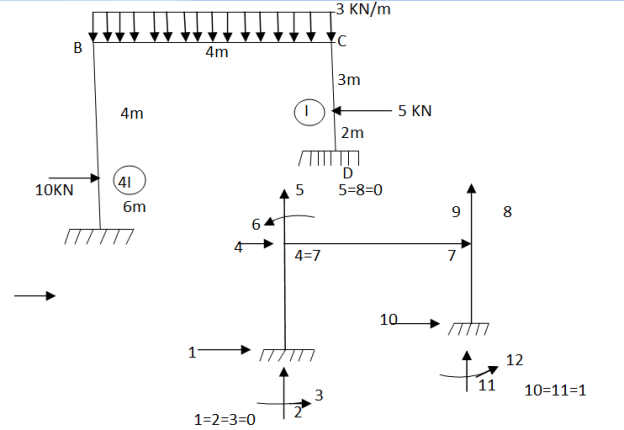
Analysis the portal frame as shown in fig. using finite element methos take EI constant. Neglect axial deformation
|
Fig.5
Step -1 total DoF =12 (three DOf at each node, two displacement & one rotation) No. of elements 03 (AB,BC,CD) Discretization
Step 2- element stiffness matrix Element stiffness matrix from AB (column member)
Imposing boundary conditions 5=8=0 Element stiffness matrix for DC
Imposing boundary conditions 10=12=0 Step -3 reduced stiffness matrix Since horizontal sway at B& C are same (4=7) we can modify the above stiffness matrix as
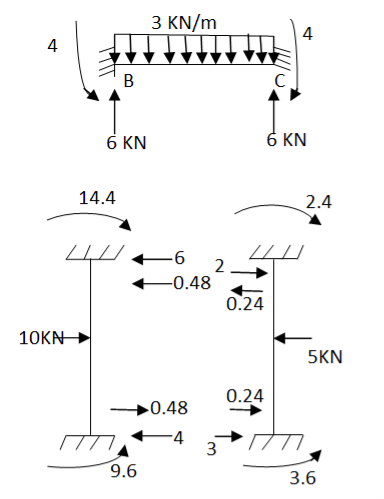
Step -4 element nodal load vector
Fig.6
Reduced element nodal load vector
Step -5 equivalent load vector {f}= {q}+ joint forces
Step -6 equation of equilibrium
Step -7 moment calculations
Member AB
Member BC
Member DC
|
Example – 2
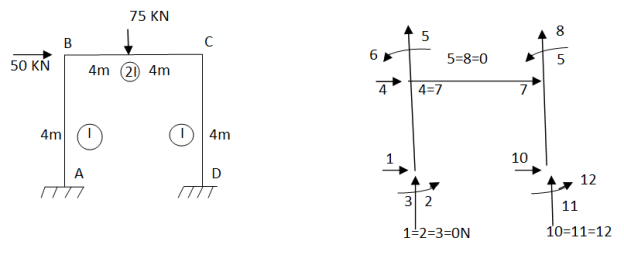
Analyze the rigid frame by using finite element method. Take EI constant . neglect axial deformation
|
Fig.7
Step -1 total DOf =12 (three dof at each node , two displacements & one rotation)
Step -2 element stiffness matrix for column AB
Element stiffness matrix of beam Bc
Element stiffnes matrix of beam DC.
Imposing boundary condition 1=2=3=5=8=10=11=12=0 Step -3 reduced stiffness matrix Since horizontal sway at B &C are same (4=7) , we can modify the above stiffness matrix as
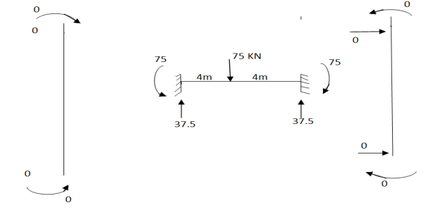
Step -4 element nodal load vector
Fig.8
Reduced element nodal load vector
Step -5 equivalent load vector
Step -6 equation of equilibrium
Step -7 moment calculations
Member AB
Member BC
Member DC
|
Example 1
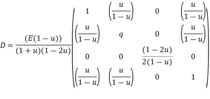
For the axisymmetric element shown in figure, determine the element stresses
Let E=210
|
Fig.9
Poisson’s Ratio=0.25
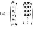
The total displacements are
u1=0.05mm ; W1=0.03mm
u2=0.02mm; W2=0.02mm
u3=0mm;W3=0mm
To Find Element Stresses & Stiffness Matrix
|
Solution:-
We know that
&
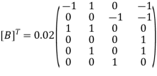
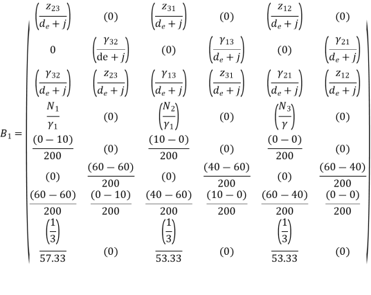
Substitute all this values in {B}
Put =E =
We know that stiffness matrix
Note ; matrix form [k]= (6*6)
To find stresses
Note – matrix form = 4*1
|
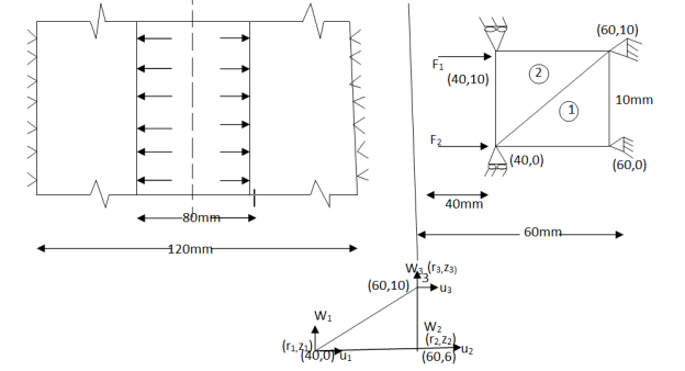
Example 2 :-
A long hollow cylinder of inside diameter 80mm & outside diameter 120mm is firmly filled in a hole of another rigid cylinder over it full length as shown in fig. the cylinder is then subjected to an internal pressure of 2 MPa. By using two elements on the 10mm length shown . find the displacement at the inner radius . take E=200 Gpa ,u=0.3
|
Fig 10
Solution -
Stiffness matrix for element 1
For the both elements
The stiffness matrices for element
|
References-
(1) Finite Element Analysis -C.S. Krishnanmoorthy, Tata McGraw Hill Publishing Co. Ltd, New Delhi,
(2) The Finite Element method -ZIENKIEWICZ.O.C.Tata McGraw Hill Pub. New Delhi, 2000
(3) Finite Element Methods by C R Alaval , PHI
(4) Finite Elements in Engineering:- Chandrupatta, et. AI. Prentice Hall of India Pvt. Ltd.,


