Unit - 5
Introduction to Kinetics of Rigid Bodies
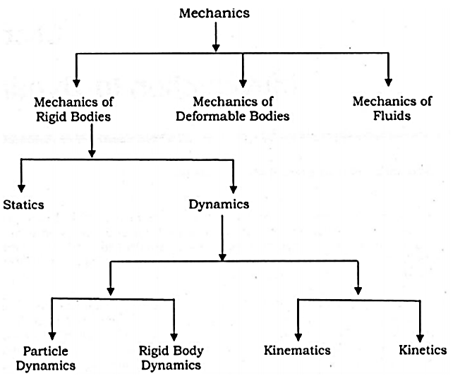
Dynamics is the branch of mechanics that deals with the motion of the particle or a rigid body. In other words, dynamics deals with the accelerated motion of a body. Analysis in dynamics involves motion. Dynamics can be sub-divided into two parts:
Kinematics is the branch of mechanics or simply a part of dynamic analysis which deals with the study or analysis of the motion of the body without considering the forces that causes this motion.
Hence Kinematics only analyses the geometry of the particle or rigid body.
2. Kinetics
Kinetics is the branch of mechanics or simply a part of dynamic analysis which deals with the study of motion of the body by considering the forces that causes this motion.
In other words, kinematics relates with the forces acting on the moving body.
Newton’s second law is the basis for kinetics. It states that when an unbalanced force acts on a particle, the particle will accelerate in the direction of the force with a magnitude that is proportional to the force.
If the mass of the particle is m, Newton’s second law of motion can be given in mathematical form as

When more than one force acts on a particle, the resultant force is defined by a vector summation of all the forces.

In general equation of motion is written as,

A rigid body is an ideal body that does not change its shape when subjected to external forces or couples. The distance between the particles in a rigid body remains same during the motion. Hence, a rigid body can be defined as the group or collection of number of particles at fixed distance from each other.
There are three types of motion of a rigid body
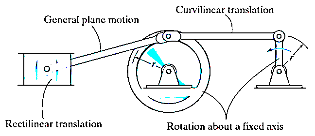
Translation motion
Translation motion occurs when a line (generally axis) in the body remains parallel to its initial orientation throughout the motion.

If the path of motion of any two lines on the rigid body are parallel or are in a straight line, then the translation is termed as rectilinear translation.
If the path of motion of any two lines on the rigid body are along the fixed curve, then the translation is termed as curvilinear translation.
Consider a rigid body that is subjected to translation motion as shown in fig.
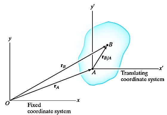
The position of points A and B is defined are defined by the position vectors  and
and  w.r.t the fixed frame x, y.
Let the translating system is fixed in a body with origin A which is referred to the base point. The position vector of B w.r.t A is denoted by  .
.
By vector addition, we get,


Taking, the first-time derivative of the above equation, we get,

According to the definition of rigid body, the term  is constant
Hence,

And,  gives the absolute velocities
  and
and  respectively with respect to the fixed frame.
So, we get,

This shows that, for the rigid body in translation motion, the velocity of every particle on the body is same.
Now, taking the time derivative of the velocity equation, it simply yields

Where,  and
and  are the absolute accelerations of points A and B on the rigid body w.r.t fixed frame.
This shows that, for the rigid body in translation motion, the velocity and acceleration of every particle on the body is same.
Rotation Motion:
When a rigid body is subjected to the rotation about a fixed axis, as shown in fig below, all the particles of the body, except those which lie on the axis of rotation, move along circular paths whose center lies on the axis of rotation.
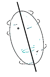
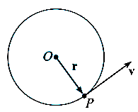
Consider, the point P on the rigid body defined by the position vector r. As the rigid body rotates about the fixed axis, then the point P travels a circular path of radius r with center point O as shown in fig below
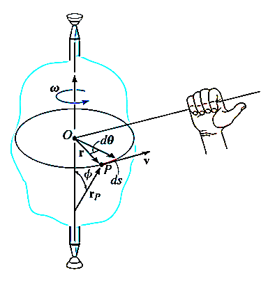
If the body rotates with a differential angular displacement  , then the point P displaces the distance
  , which is given by

Differentiating the above equation w.r.t time, we get

The term,  is referred to as the angular velocity
  of the rotating body
And  gives the velocity of point P
Hence,

The direction of velocity is tangent to the circular path.
Considering the magnitude and direction, velocity is the cross product of angular velocity and the position vector

Where,  is directed from axis to the point P
To find acceleration, differentiate velocity vector w.r.t time

Here, the term  refers to the angular acceleration
  of the rigid body
And  is the velocity
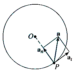
Hence,


Where,  is the tangential acceleration and
  is normal component of acceleration
Hence,

Magnitude of both components is given by,


Tangential component refers to the time rate of change of velocity’s magnitude. Hence, if velocity of point P is increasing,  is in same direction of
  , but if velocity of point P is decreasing,
  is in direction opposite to that of
The normal component of acceleration refers to time rate of change of the velocity’s direction. Hence, the direction of the normal component is always from point P towards the center O. Hence it is also called as centripetal acceleration.
General Plane motion:
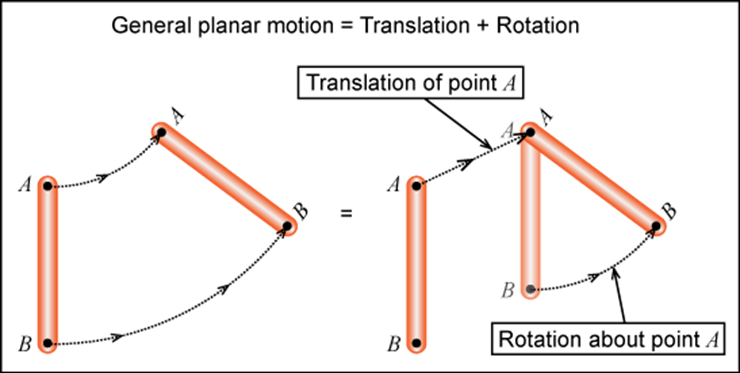
General plane motion of a rigid body refers to a combination of translation and rotation motion.
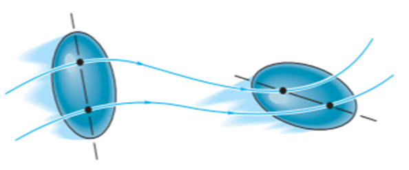
General planar motion refers to the simultaneous rotational and translational motion of a planar body in a 2-D plane.
General planar motion can be fully specified by knowing both the angular rotation of a line fixed in the body and the motion of any point on the body.
These motions can be related by using a rectilinear position coordinate s to locate the point along its path and an angular position coordinate  to specify the orientation of the line. Then these two coordinates are related using the geometry of the problem. The following relation is found.

Differentiating the above equation, gives the relation between velocity  and angular velocity
  .
.
Where,

Then again differentiating, it yields to the relation between acceleration  and angular acceleration
Where,


Consider a plane body P having a non-linear motion relative to another plane body q as shown in figure below.
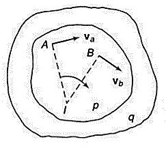
Let the velocities of two points A and B on the plane body P be  and
and  respectively in the direction as shown in figure above.
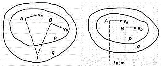
The body if in non-linear motion, then at any instant the body can be imagined to be rotating about some point. This point lies on the line perpendicular to the direction of vibration. If we draw perpendicular lines to the direction of velocities at point A and B respectively, then the point of intersection is the point at which the body p is imagined to be rotating. Let this point be 1. Then point 1 is called as instantaneous center of rotation (ICR) for the body p in non-linear motion.
This property of instantaneous center of rotation is true only for an instant and at the next instant, the new point will become the instantaneous point of rotation. This is the reason that this point is not called as center of rotation but instantaneous center of rotation.
ICR is not located at the center of curvature of the path apparently taken by a point of one body relative to other body. In spite of this limitation, ICR is a useful tool for understanding the kinematics of a planar body in non-linear motion or in general plane motion.
If the intersection of the perpendicular lines lies outside planar body, then ICR will also lie outside of the body. If the direction of velocities are parallel to each other, then the perpendicular lines will also be parallel to each other and hence, these lines do not intersect. In such cases, ICR lies at infinity.
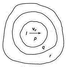
The velocity of the body at any point is proportional to the distance of the point from the ICR. Hence, the velocity of point 1 (ICR) itself is zero, as the distance is zero. This implies that, at ICR, the two bodies p and q are relatively at rest. Means, there is no relative motion at ICR between the two bodies.
Now, consider the body q is in relative motion to the third body r. The relative motion of ICR with respect to third body r would be same irrespective of the point is considered on body p or q.
D’Alembert’s principle states that, “if at any given moment to the active forces and the reactions of the constraints acting on a particle or rigid body is added the inertia force, the resultant force system will be in equilibrium and all the equations of statics will apply to it.”
D'Alembert’s principle provides a method of solving problems of dynamics by developing equations of motion in the form of equations of equilibrium.
In simple words, D’Alembert’s principle is just the principle of virtual work with the inertial forces added to the list of forces that do work.
Consider a body in general plane motion as shown in figure below.
Consider this body is at rest and let  be the resultant external forces acting on a rigid body and
  be the virtual displacement of the body is s direction.
Then according to principle of virtual work,

This method is used for solving statics problems. In statics problems there are no accelerations.
We can extend this principle of virtual work for solving dynamics problems.
For the system of mass m and resultant acting forces  , according to Newton’s second law of motion,

We can make this dynamics problem look like a statics problem by defining an inertial force given by,

Now, for dynamics problems, principle of virtual work becomes,

As the virtual displacement is same for both the active forces and inertia forces,

This is D’Alembert’s principle used for solving the dynamics problems by using the concept of equilibrium conditions.
The above equation can be written as


Considering the rigid body in general plane motion as shown in figure below:
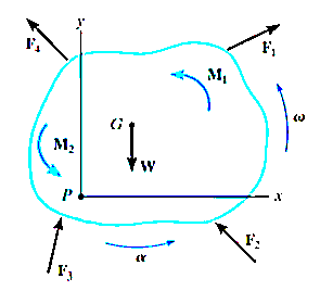
Applying D’Alembert’s principle, three independent scalar equations can be written to describe the general plane motion of a symmetrical rigid body.


These equations are called as equations of motion.
When applying these equations, one should always draw a free-body diagram.
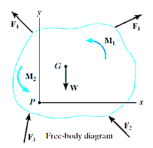
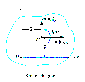
In some problems it may also be helpful to draw the kinetic diagram for the body. This diagram graphically accounts for the terms  ,
,  and
and  .
.
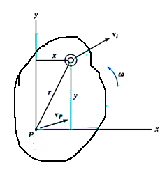
Consider the rigid body as shown in Figure, which is represented here by a slab moving in the inertial x–y reference plane.
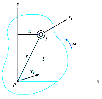
An arbitrary ith particle of the body, having a mass dm, is located a distance r from the arbitrary point P. If at the instant shown the particle has a velocity then the particle’s kinetic energy is

The kinetic energy of the entire body is determined by integrating above equations

Solving above equation when point P coincides with center of mass of the body G, we get

Where,
 = velocity of center of mass or simply velocity of rigid body
 = mass of whole body
 = Mass moment of inertia of a body about an axis passing through center of mass G
 = angular velocity of a body
When a rigid body is subjected to general plane motion with an angular velocity  and its mass center has a velocity of
  , then kinetic energy is given by

Work by a force for a rigid body
If an external variable force F acts on a body to move the body along the path s with displacement ds, then the work done is given by,

Where,  is the angle between the “tails” of the force and the differential displacement.
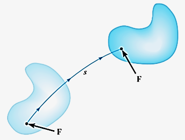
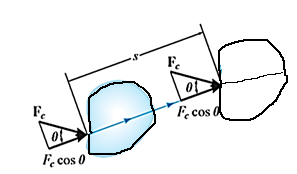
If an external constant force FC (constant in magnitude FC and direction  ) acts on a body to move the body along the path s with translation displacement s, then the work done is given by integrating above equation.
Hence,

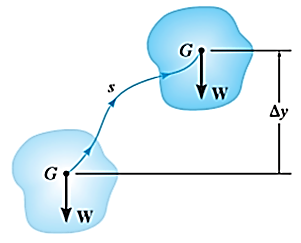
The weight W of a body does work when the center of mass G of a body undergoes a vertical displacement  .
.

If a linear elastic spring is attached to a body, the spring force  acting on the body does work when the spring either stretches or compresses from
  to a further position
  . In both cases the work will be negative since the displacement of the body is in the opposite direction to the force. The work is given by,

There are some external forces that do no work when the body is displaced. These forces act either at fixed points on the body, or they have a direction perpendicular to their displacement. Examples include the reactions at a pin support about which a body rotates, the normal reaction acting on a body that moves along a fixed surface, and the weight of a body when the center of gravity of the body moves in a horizontal plane.
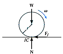
Work by a couple moment for a rigid body
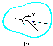
Consider the body shown in Fig a, which is subjected to a couple moment  that displaces the body through an angular displacement of
  about an arbitrary point O.
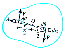
Then each force undergoes a displacement of  in the direction of the force.
Hence work done is given by


When the body rotates in the plane through a finite angle  measured in radians, from
  to
to  , the work of a couple moment is therefore given by

If the couple moment has constant magnitude, then

Principle of Work and Energy
By applying principle of work and energy to all the particles of the rigid body and adding all the results algebraically as energy is a scalar quantity, we get

Where,
 is work done by all the external forces and couple moments acting on the body
 is the body’s total initial translational and rotational kinetic energy.
 is the body’s total final translational and rotational kinetic energy.
Consider the rigid body (or slab) shown in Figure, which is constrained to rotate in the vertical plane about a fixed axis perpendicular to the page and passing through the pin at O.
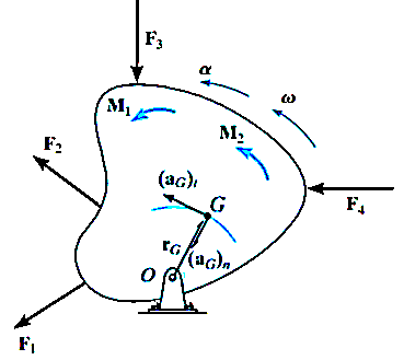
The angular velocity and angular acceleration are caused by the external force and couple moment system acting on the body. Because the body’s center of mass G moves around a circular path, the acceleration of this point is best represented by its tangential and normal components. The tangential component of acceleration has a magnitude of

It must act in a direction which is consistent with the body’s angular acceleration  .
.
The magnitude of the normal component of acceleration is

This component is always directed from point G to O, regardless of the rotational sense of  .
.
The free-body and kinetic diagrams for the body are shown in Fig (a) and (b) respectively below.
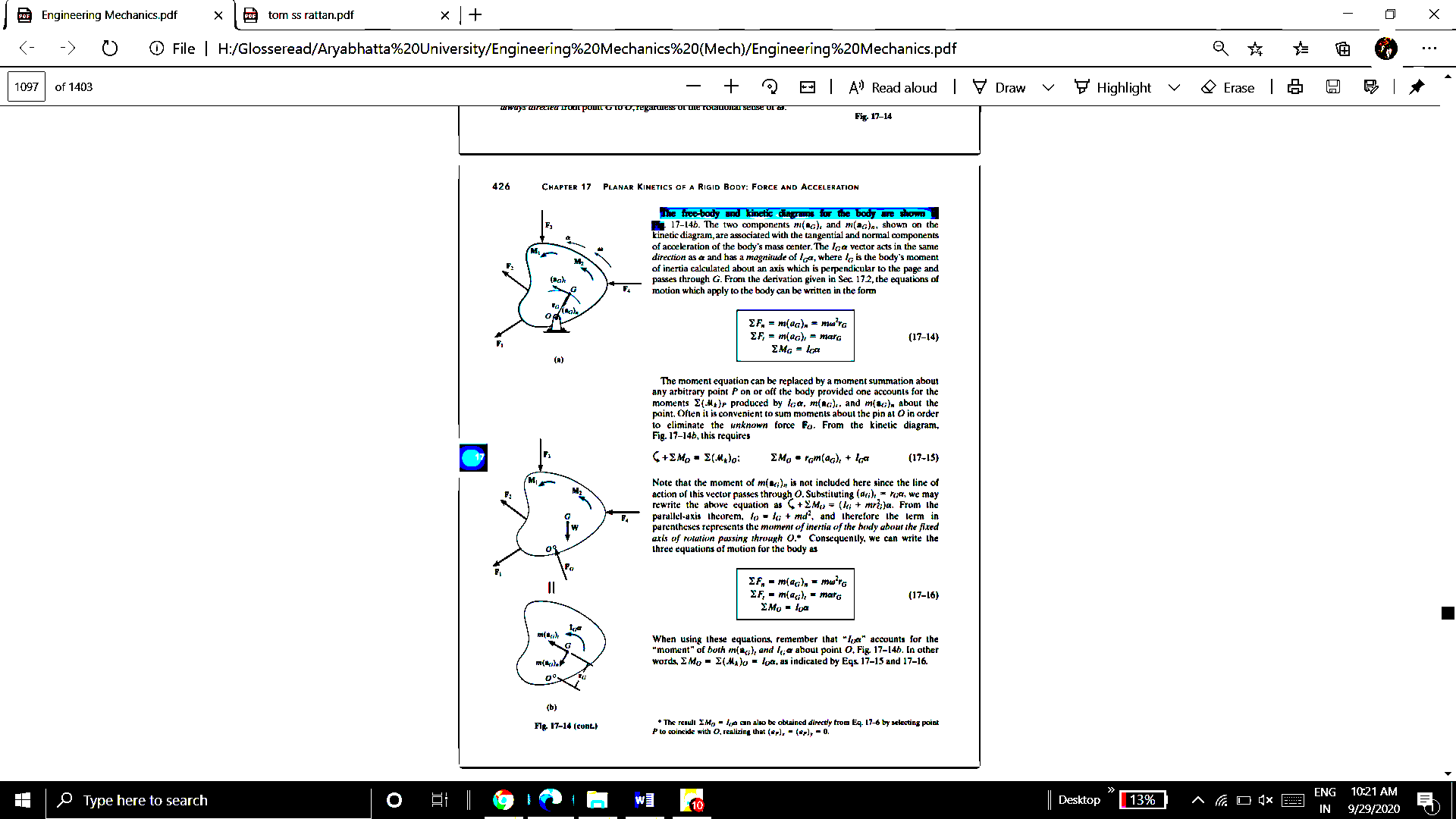
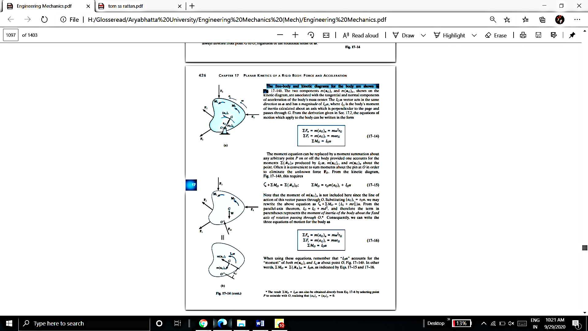
The two components  and
and  shown on the kinetic diagram, are associated with the tangential and normal components of acceleration of the body’s mass center.
The vector  acts in the same direction as
  , where
  is the body’s moment of inertia calculated about an axis which is perpendicular to the page and passes through G. The equations of motion which apply to the body can be written in the form


If the body rotates about an axis perpendicular to plane of body and passing through point O which is at a distance of d from CG. Then the equations of motion which apply to the body can be written in the form


Where, 
In general, the definitions of the work of a force and a couple can be presented in terms of the actual movements which are expressed by differential displacements having values of  and
and  .
.
Consider now an imaginary or virtual movement of a body in static equilibrium, which indicates a displacement or rotation that is assumed and does not actually exist. This displacement is called as virtual displacement.
Virtual displacement is the displacement the force or couple would make on a body if the body was not in the static equilibrium or its motion would not be constrained.
These movements are first-order differential quantities and will be denoted by the symbols  and
and  (delta r and delta
  ), respectively.
The virtual work done by a force having a virtual displacement  is
is

Similarly, when a couple undergoes a virtual rotation  in the plane of the couple forces, the virtual work is

Consider a ball that rests on a floor. If there was no floor below the ball, then the ball would have been displaced due to its own weight. Then this imaginary displacement of the ball is nothing but the virtual displacement.
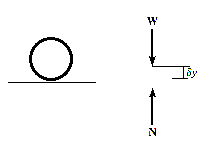
The principle of virtual work states that if a body is in equilibrium, then the algebraic sum of the virtual work done by all the forces and couple moments acting on the body, is zero for any virtual displacement of the body.
Thus,

For example, consider the free-body diagram of the particle (ball) that rests on the floor, Fig. below. If we “imagine” the ball to be displaced downwards a virtual amount  then the weight does positive virtual work
  , and the normal force does negative virtual work
  , For equilibrium the total virtual work must be zero, so that

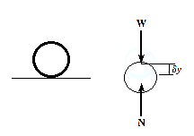
Since,  ,
,
Then,  , as required by
As seen from the above example, no added advantage is gained by solving particle and rigid-body equilibrium problems using the principle of virtual work. This is because for each application of the virtual-work equation, the virtual displacement, common to every term, factors out, leaving an equation that could have been obtained in a more direct manner by simply applying an equation of equilibrium.
Principle of virtual work for ideal system of rigid bodies
In a similar manner, as that of particle, we can also apply the virtual-work equation  to a rigid body subjected to a coplanar force system.
Here, separate virtual translations in the x and y directions and a virtual rotation about an axis perpendicular to the x–y plane that passes through an arbitrary point O, will correspond to the three equilibrium equations,


When writing these equations, it is not necessary to include the work done by the internal forces acting within the body since a rigid body does not deform when subjected to an external loading, and furthermore, when the body moves through a virtual displacement, the internal forces occur in equal but opposite collinear pairs, so that the corresponding work done by each pair of forces will cancel.
To demonstrate an application, consider the simply supported beam in Fig(a). When the beam is given a virtual rotation about point B, Fig(b), the only forces that do work are P and Ay
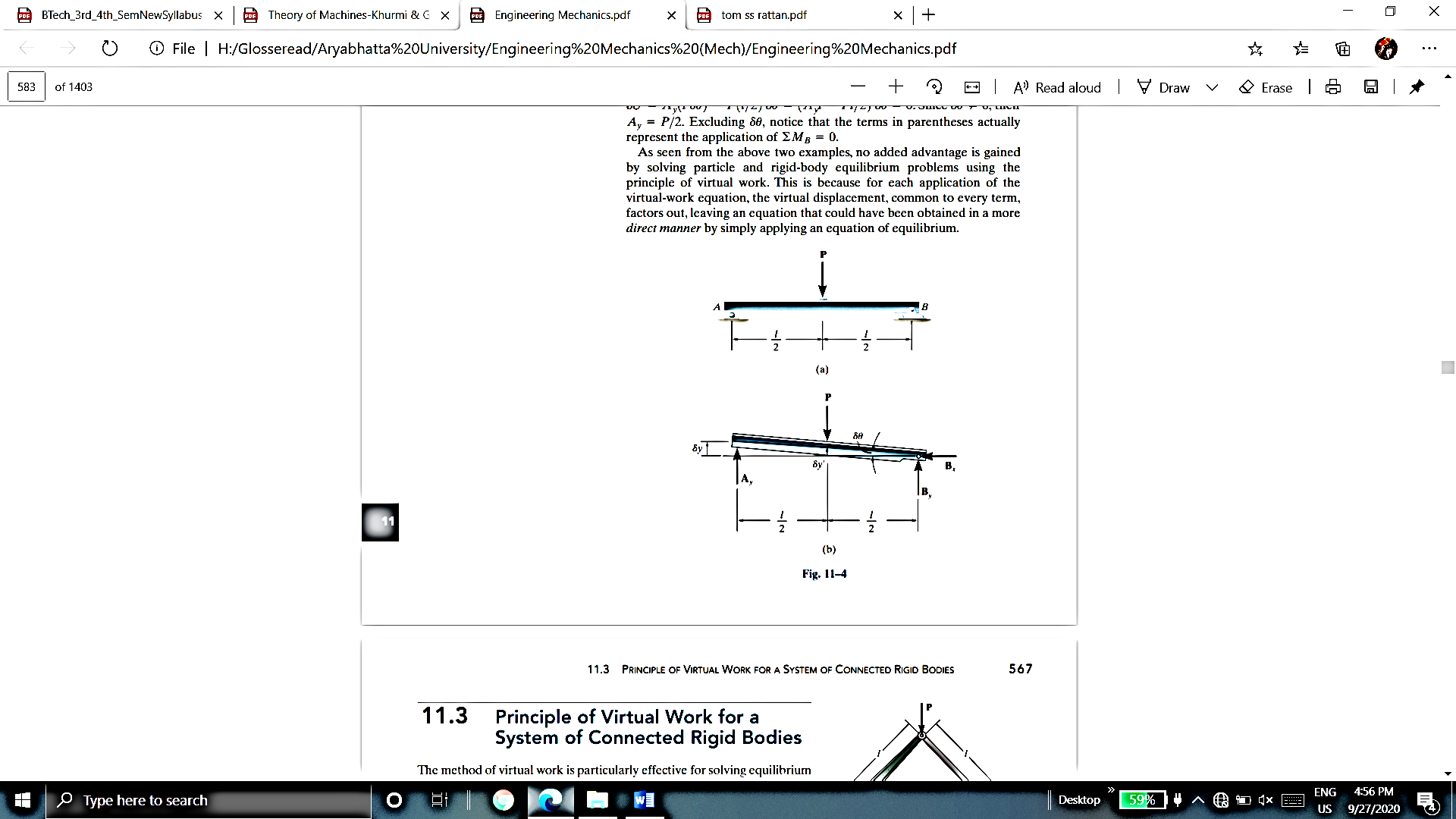
Since,

And

The virtual work equation for this case is


Since,  ,
,

Excluding  , notice that the terms in parentheses actually represent the application of
The method of virtual work is particularly effective for solving equilibrium problems that involve a system of several connected rigid bodies, such as the ones shown in Figure below.
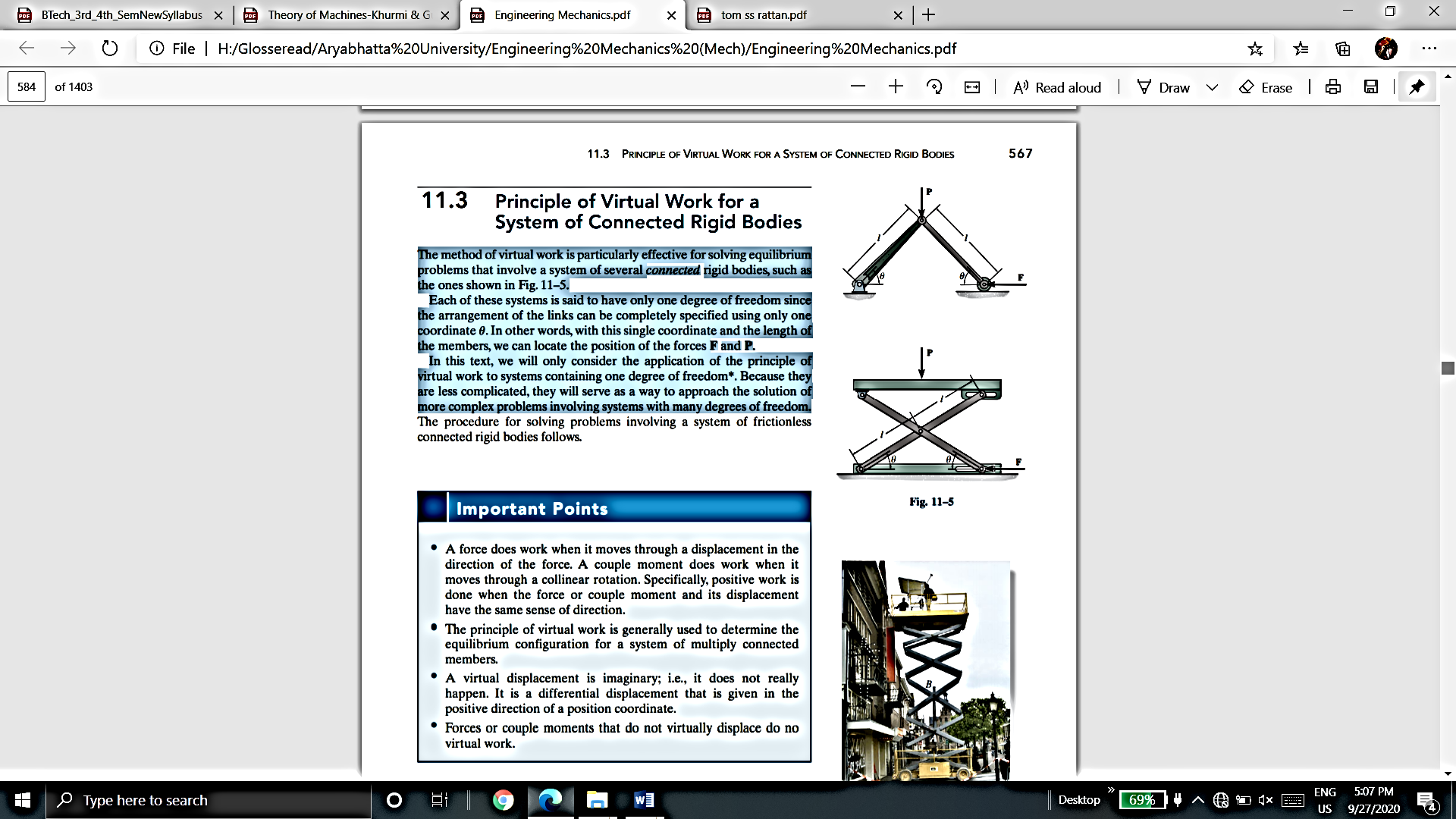
Each of these systems is said to have only one degree of freedom since the arrangement of the links can be completely specified using only one coordinate. In other words, with this single coordinate and the length of the members, we can locate the position of the forces F and P.
This energy equation can be applied to a mass under gravitational force or a spring either elongated or compressed or a system of both mass and spring.
Consider a spring block system as shown in figure below
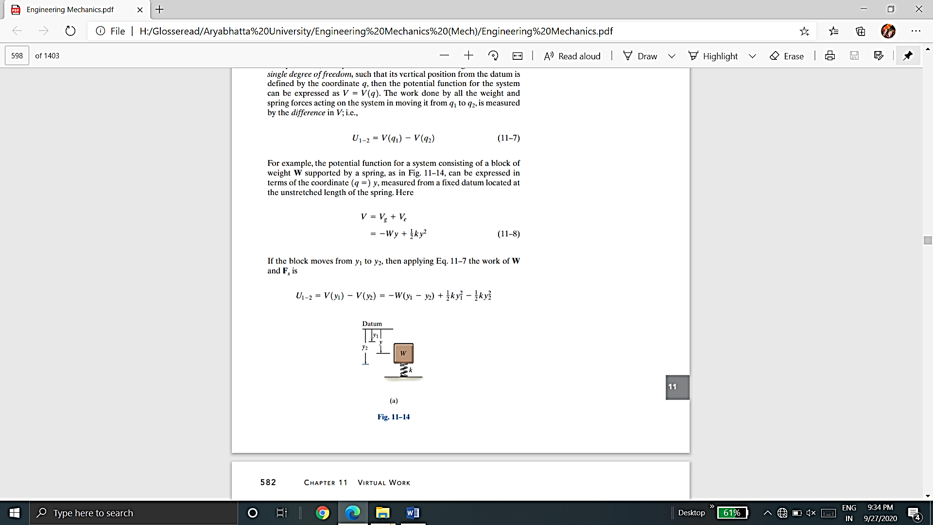
The potential function for a system consisting of a block of weight W supported by a spring, as in Figure, can be expressed in terms of the coordinate measured from a fixed datum located at the unstretched length of the spring. Here


Using energy equation, we can determine the equilibrium position for the spring and block.
We have,

Hence, the equilibrium position is

The potential function V of a system can also be used to investigate the stability of the equilibrium configuration, which is classified as stable, neutral, or unstable.
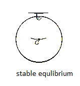
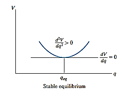
Stable Equilibrium: A system is said to be stable if a system has a tendency to return to its original position when a small displacement is given to the system. The potential energy of the system in this case is at its minimum. A simple example is shown in Fig. below. When the disk is given a small displacement, its center of gravity G will always move (rotate) back to its equilibrium position, which is at the lowest point of its path. This is where the potential energy of the disk is at its minimum.
The graph represents stable equilibrium for one degree of freedom system.
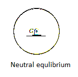
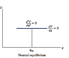
Neutral Equilibrium: A system is said to be in neutral equilibrium if the system still remains in equilibrium when the system is given a small displacement away from its original position. In this case, the potential energy of the system is constant. Neutral equilibrium is shown in Fig. below, where a disk is pinned at G. Each time the disk is rotated, a new equilibrium position is established and the potential energy remains unchanged.
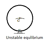
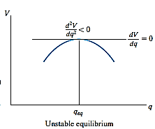
Unstable Equilibrium: A system is said to be unstable if it has a tendency to be displaced further away from its original equilibrium position when it is given a small displacement. The potential energy of the system in this case is a maximum. An unstable equilibrium position of the disk is shown in Fig. below. Here the disk will rotate away from its equilibrium position when its center of gravity is slightly displaced. At this highest point, its potential energy is at a maximum.
Stability in one degree of freedom system:
If a system has only one degree of freedom, and its position is defined by the coordinate q, then the potential function V for the system in terms of q can be plotted.
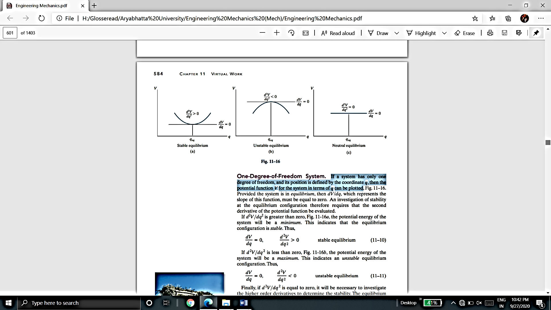
Provided the system is in equilibrium, then dV/dq, which represents the slope of this function, must be equal to zero. An investigation of stability at the equilibrium configuration therefore requires that the second derivative of the potential function be evaluated.
If  is greater than zero, the potential energy of the system will be a minimum. This indicates that the equilibrium configuration is stable.
Hence, for stable equilibrium,

If  is less than zero, the potential energy of the system will be a maximum. This indicates that the equilibrium configuration is unstable.
Hence, for unstable equilibrium,

Finally, if  is equal to zero, it will be necessary to investigate the higher order derivatives to determine the stability. The equilibrium configuration will be stable if the first non-zero derivative is of an even order and it is positive. Likewise, the equilibrium will be unstable if this first non-zero derivative is odd or if it is even and negative. If all the higher order derivatives are zero, the system is said to be in neutral equilibrium.
Hence, for neutral equilibrium,

This condition occurs only if the potential-energy function for the system is constant at or around the neighborhood of  .
.
References:
1. Irving H. Shames (2006), Engineering Mechanics, 4th Edition, Prentice Hall
2. F. P. Beer and E. R. Johnston (2011), Vector Mechanics for Engineers, Vol I - Statics, Vol II, – Dynamics, 9th Ed, Tata McGraw Hill
3. R. C. Hibbler (2006), Engineering Mechanics: Principles of Statics and Dynamics, Pearson Press.
4. Andy Ruina and Rudra Pratap (2011), Introduction to Statics and Dynamics, Oxford University Press
5. Shanes and Rao (2006), Engineering Mechanics, Pearson Education