Unit-1
Introduction to soil exploration
SOIL EXPLORATION AND SITE INVESTIGATION:
Purpose of the soil exploration program
Site investigation for one or a lot of the following purpose:
Factor affecting the cost of soil investigation:
1. Non-uniformity of layers
2. Undisturbed sampling
3. Depth of exploration
4. Nature of the project
Non-uniformity of layers
Erratic deposits would like a lot of exploration price than homogenous deposits.
Undisturbed sampling
Need serious expenditure
Depth of explorations
The cost will increase with increases in comprehensive exploration.
Nature of the project
STEPS IN SOIL EXPLORATION
Soil exploration involves broadly the subsequent
1. Planning of a program for soil exploration
2. Collection of saturated and undisturbed soil or neck samples from the hales dilled within the field the amount and died of boles depend on the project
3 Conducting all the required in-situ for large the strength and compatibility characteristics of the soil or rock directly or indirectly
4. Study of groundwater conditions and action of water samples for analysis
The bottom investigation, regardless of the magnitude of the project, consists of 4 phases
Four phases of ground Investigation
1. Available information
2. Reconnaissance
3. Preliminary inventory
4. Detailed investigation
1. Available information
2. Reconnaissance
At this stage, a radical study of the present structures for the sort of construction and defects such a hi and settlement, soil profiles in highway or railroad cuts and quarries, version in existing cuts, high watermarks on bridge abutments, outcrop, history cal food and scour levels from the local people are collected.
3. Preliminary investigation
This is a vital phase of the complete program during this stage the engineering plant the investigation program. The primary step towards a ground investigation could be a thorough understanding of the geology of the location, which cables an efficient understanding of the investigation program.
The second step is to get additional details of the under soil strata (e. g. thickness of individual strata) from one or 2 explorative drill holes. All alternative more steps rely upon the magnitude of the work and therefore the character of the soil profile.
During this stage, the attainable location of the bottom water is additionally found. For tiny jobs, the skinny preliminary investigation itself is also sufficient. It istypical to apply to limit the number of quality samples recovered except the one obtained from penetration tests.
The strength and settlement are calculable from standard correlations mistreatment index properties and supplemented by the results from samples obtained from penetration tests. Further, will be} the stage that much decide the flexibleness of the project.
4. Detailed investigation
Additional borings and deep borings are planned from the information obtained from the preliminary borings and deep borings. If the under soil is uniform in stratification, an orderly spacing is also planned.
Many times, extra borings are created to find weak soil or rock zones, outcrops and so on which can influence the planning and construction of the project. Drilling is needed to bore a hole into exhausting strata boulders. It can be done by percussion or rotary methodology of drilling.
Necessary unchanged tests ought to also be having sufficient samples ought to be procured to get relevant parameters for design and construction. Such extra samples should be recorded to redefine the planning or construction procedure.
Key Takeaways
Soil exploration -
Introduction
Purpose
Factor affecting
Steps of soil exploration
Bottom investigation- available investigation, reconnaissance, preliminary inventory, detailed investigation
Following methods are used to obtained soil samples to identify the type of start and to send the same for testing.
Methods -
1 trial pits
2 Auger boring
3 wash boring
4. Rotary drilling, core drilling
5. Percussion drilling
1. Trial pits and trenches
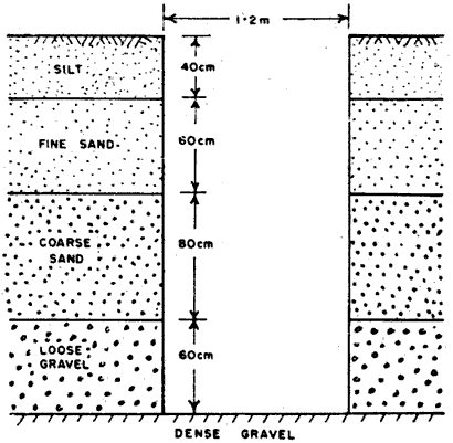
Fig no. 1 Trial pit and trenches
TRENCHES
This square measure the same as check pits. They supply a protracted continuous exposure of the surface of the bottom on a desired line or section. They are best suited to exploration on slopes. Necessary safety precautions need to be taken as in deep check pits.
2. Auger boring
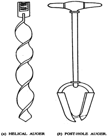
Fig no. 2 Auger drilling
3. Wash boring
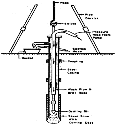
Fig no. 3 Wash boring
Advantages
1. Instrument used is relatively light-weight in weight.
2. Cheap technique
3. Quick and easy technique.
Disadvantages
1. it's slow in stiff and coarse-grained soils.
2. Can't be employed in rocky strata.
3. Sensible quality undisturbed samples can't be obtained
4. Not appropriate in areas wherever the H2O table is incrediblynear to the ground
4. Rotary drilling:
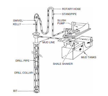
Fig no. 4 Rotary drilling
Advantages:
1 Rotary drilling can be used in clay, sand, rocks.
2 boreholes of diameter 50 mm to 200mm can be easily drilled by this method.
Disadvantages:
If soil is containing a large percentage of practical gravel size and larger this method is not well adapted because the particles of this size start rotating below the drill rod and it becomes difficult to drill the hole.
5. PERCUSSION DRILLING:
DEFINITION The machinery accustomed to advanced Holes and cake sample is named a drilling rig
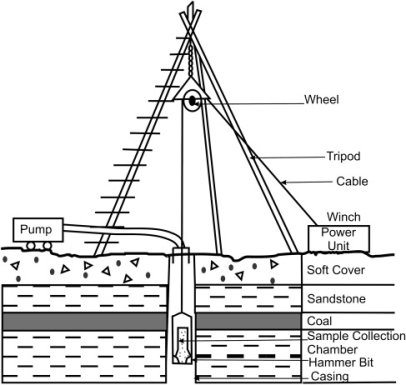
Fig no. 5 Percussion drilling
Advantages
1. Percussion drilling is employed in every type of soil.
2. it's noticeably helpful for boring holes like that for well through rock or boulders.
Disadvantages
1. Due to significant blows of the chisel, the fabric at very cheap is disturbed.
2. Costlier as compared to alternative ways
Key takeaway
Methods of obtaining soil sample –
Type of samplers
1. Open Drive Sampler
2. Stationary Piston Sampler
3. Split Barrel or Split Spoon Sampler
4. Rotary Sampler
5. Disturbed and Undisturbed Sampling
6. Block or Chunk Samples
1. Open drive sampler
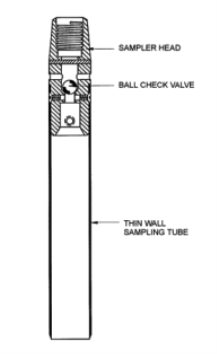
Fig no. 6 Open drive sampler
2. Stationary piston sampler:
Here we have a thin-walled tube fitted with a piston the piston is connected to a rod passing through the sampler head and run inside a hollow boring rod.

Fig no. 7 Stationary piston sampler
3. Split barrel or Split Spoon Sampler

Fig no. 8 Split barrel
![Quiz] Rotary Drilling - OILMAN Magazine](https://glossaread-contain.s3.ap-south-1.amazonaws.com/epub/1642793440_1481264.png)
Fig no. 9 Rotary sample
5. Disturbed and undisturbed sampling
6. Block or Chunk Sample
DEPTH OF EXPLORATION AND EXTEND
Depth of Exploration
Extend of exploration
FACTOR AFFECTING DISTURBANCE TO SOIL SAMPLE
1. Area ratio
2. Inside and outside clearance
3. Cutting edge angle
4. The effect of area ratio on sampling tube
5. Sampling speed
6. The material used for sampling tube
7. Roundness
8. Recovery ratio (Fr)
9. ROD, Rock Quality Designation
Key takeaways
TYPES OF SAMPLER
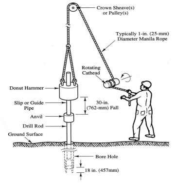
Fig no. 10 Standard penetration test
The take a look at is halted If
(a) 50 blows area unit needed for any a hundred and fifty metric linear unit penetration
(b) one hundred blows area unit needed for three hundred penetration.
(c) 10 sequent blows turn out no advance and are termed as a refusal.
The following precautions ought to be taken whereas closing the take a look at
(a) The split spoon sampler should be in condition and the cutting shoe should be free from wear tear.
(b) The drop press should be of the correct weight and the fall ought to be free resistance.
(c)Very cheap of the borehole should be properly clean before the take a look at is administrated. Otherwise, the take a look at gets administrated within the loose, disturbed soil and not within the undisturbed soil.
(d) Once a casing is employed in the borehole, it ought to be ensured that the casing is driven simply by wanting level at that the S P T is to be administrated. Otherwise, the take a look at gets administrated in a very soil of very cheap of the casing
Limitations of SPT
1. As SPT is subject to several errors, the S P T price isn't reliable.
2 In granular soils, the correlation between S P T and internal friction angle is incredibly poor.
3. Determination of allowable bearing pressure from N values isn't correct.
4. S P T price isn't acceptable for determinant the bearing pressure in fine-grained cohesive soils,
5. Corrections for overburden and impact square measure to be applied to record N values for correlation with soil properties
Applications of SPT
1. At the start the cone and therefore the friction jacket assembly is during a stationary position
2. The cone is then pushed into the soil at the speed of a pair of20 mm /s by the inner sounding rod at a gradual rate until a collar engages the cone. The force Qc offered by soil for penetration measured on the gauge, and tip resistance purpose resistance. Qt is calculated by q c =Q c /Ac
Where Ac is the base area
3. The sounding rod is pushed more pushing the friction jacket and therefore the cone assembly along. The entire force alphabetic character, needed for this is often once more pressure gauge.
Qt = Qc + Q f, where Q f = force needed to push friction jacket
From this skin friction, fs is calculated
Fs =Q f/A f
Where A f is that the extent of friction jacket.
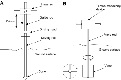
Fig no. 11 Cone penetration
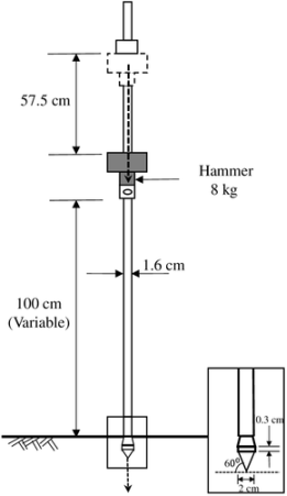
Fig no. 12 Dynamic cone penetration
1. 5 N for 3m depth
1. 75N for 3 to 6m depth
2. 0N for greater than 6 m depth
Most commonly used geophysical methods in soil exploration
1. Seismic refraction method
2. Electrical resistivity method (soil resistivity)
Principle –
This method is based upon the principle that electrical resistance offered by different types of soil to the flow of current is different
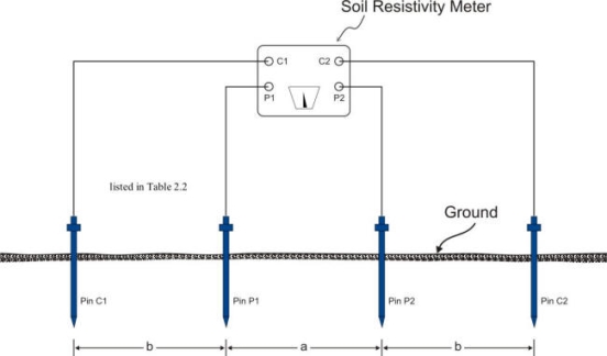
Fig no. 13 Soil resistivity method
The soil impedance price is subject to nice variation, because of wet, temperature, and chemical content. Typical values are:
Usual values: from ten up to one thousand (Ω-m)
Exceptional values: from one thousand up to ten thousand (Ω-m)
The SI unit of impedance is that the Ohm-meter (Ω-m); within the U.S. the Ohm-centimeter (Ω-cm) is commonly used instead. One Ω-m is one hundred-one hundred. Generally, the conduction, the reciprocal of the impedance, is quoted instead.
Principle
Method
D1 = 0. 5 * x1 *square root of [(v2-v1)/(v1+v2)]
Where
X1 = distance from the y-axis to point of intersection of first 2 straight lines.
X2 = distance from the y-axis to point of intersection of 2 straight lines.
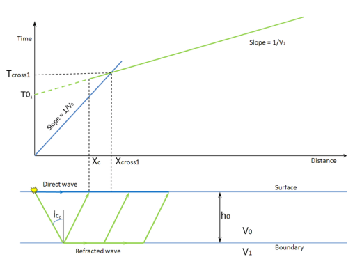
Fig no. 14 Seismic refraction method
Limitations of this technique
1. Materials like dense gravel, stiff clay, dirt, or rock have characteristic seismic speed, thus can't be known by the distance-time graph.
2. Just in case of blind zone wherever layer with speed not up to that of higher layer exists can't be detected by seismic refraction,
Key takeaways
There are mainly 3 tests
Geophysical methods
Reference:
1. “Geotechnical Engineering” by S L Gulhati and M Datta
2. “Applied Analysis in Geotechnics” by F Azizi
3. “Essentials of Soil Mechanics and Foundations: Basic Geotechnics” by DF McCarthy