Back to Study material
FD

Unit-3

Design of shallow foundation


To perform satisfactorily:

  • The foundation should be safe against overall shear failure within the soil that supports it. (bearing capacity)
  • The foundation cannot endure excessive displacement settlement.
  • Design considerations

  • Foundations should be designed each structurally and geotechnical
  • Able to safely carry compression, tension and shear hundreds, and potential moments
  • Structurally economical
  • Geotechnical economical
  • Take tolerance of structure to movement under consideration
  • FOUNDATION TYPES

    SHALLOW

  • The soil layer is appropriate for supporting a structure at a comparatively shallow depth
  • DEEP

  • The upper layer of soil isn't appropriate to carry/support a structure. the burden of the structure is transferred to stable layers at bigger depths (piles, piers, caissons)
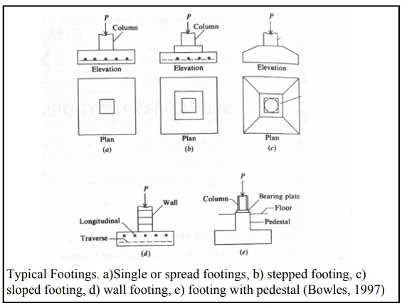
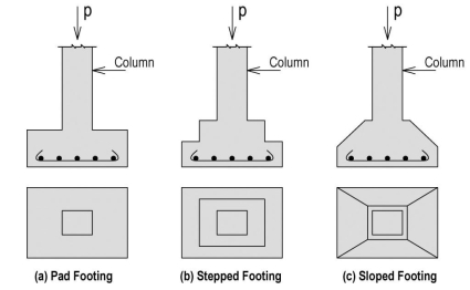
  • Fig no. 1 Types of shallow footing

    SINGLE FOOTING

    Types

  • Masonry footings (very lightweight loads)
  • Timber grillage footings (temporary buildings)
  • Steel grillage footings (large shear stresses, serious loads)
  • Plain concrete footings (light column load)
  • ferroconcrete footings (high bearing capacity)
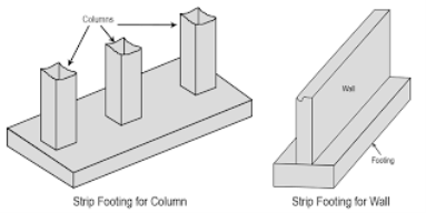
  • A strip footing (continuous footing) supports a load wall or cluster of columns.

    Combined Footing supports a variety of columns.

    SHALLOW FOUNDATION DESIGN

  •  All hundreds which will act on foundations ought to be studied and determined.
  •  Site investigation ought to be allotted.
  • The depth of the foundation should be determined.
  • Foundations should be analyzed with relevancy 2 failure types:
  • Settlement failure
  • Bearing capability failure
  • BEARING CAPACITY

  • Safe Bearing capability is that the worth of gross pressure that will be applied while not the danger of shear failure.
  •  Allowable Bearing capability (qa) is that the most (net) pressure which can be applied to the soil such that:
  • F.S. against the shear failure of supporting soil is adequate Fs = 2 or 3
  • The total and differential settlements are measures at intervals within permissible limits.
  • Ultimate Bearing capability (qu l t) is that the least (gross) pressure that will cause shear failure within the locality of the muse.
  • TERZAGHIS BEARING CAPACITY THEORY FOR SHALLOW FOUNDATION

  • According to this theory, a foundation is shallow if the depth, D, of the muse, is a smaller amount than or adequate the breadth of the muse. Df =3 to 4B thought of shallow.
  • Terzaghi advised that for a never-ending or strip foundation, the failure surface in the soil at final load is also assumed to be almost like that shown within the figure.
  • The impact of soil higher than very cheap of the muse might also be assumed to get replaced by the same surcharge, q=
    Df
  • The failure zone beneath the muse will be separated into three elements.
  • For a strip footing:

    q u l t = 1/2 BN   + c N c + Df N q

    Where

    Qu: final bearing capability

    N: Bearing capability issue because of the weight of soil with zero surcharge

    N c: Bearing capability issue because of cohesion of soil, presumptuous soil to be weightless and surcharge as zero

    N q: Bearing capability issue because of surcharge pressure, q o= D associate horizontal plane at foundation base level, presumptuous soil below foundation as weightless

    For a square footing with aspect B

    q u l t = 0.4 BN + 1.3 c N c  + Df N q

    For a circular footing with diameter D:

    q u l t = 0.3 D N + 1.3 c N c + Df N q

    Note: For an oblong footing (L*B) use linear interpolation between strip footing (B/L=0) and sq. footing (B/L=1.0)

    N c rect = N c strip [1 + 0.2 (B/L)]

    N rect = Nstrip [1 - 0.2 (B/L)]

    N q rect = N q strip

    *For identical soil conditions, for various foundation shapes, q u l tvalues square measure differently.


    Key takeaways

  • Mainly there are two types of foundation and deep foundation
  • Shallow foundation

    Deep foundation

  • There are different types of single shallow footing
  • Masonry, steel, plain concrete like

  • Foundation should be analyzed with relevancy 2 failure types
  • Settlement failure

    Bearing capability failure


    The main objectives of foundation style are to make sure that the structural masses are transmitted to the subsoil(s) safely, economically, and with none unacceptable movement throughout the development amount and the anticipated lifetime of the building or structure

    Basic style Procedure

    This can be thought-about as a series of steps or stages

  • Assessment of web site conditions within the context of the location and soil investigation report.
  • Calculation of anticipated structural loading(s).
  • Choosing the inspiration kind taking into thought.
  • Soil conditions.
  • Type of structure.
  • Structural loading(s).
  • Economic factors.
  • Time factors relative to the projected contract amount.
  • Construction issues.
  • Sizing the chosen foundation within the context of loading(s), ground bearing capability, and any probable future movements of the building or structure.
  •  


    Isolated footing

  • Isolated footings (also referred to as Pad or unfold footings) area unit ordinarily used for shallow foundations to hold and unfold targeted hundreds, caused as an example by columns or pillars. Isolated footings will consist either of strengthened or non-reinforced material. For the non-reinforced footing but, the peak of the footing should be larger to produce the mandatory spreading of the load.
  • Categories of isolated foundation footings | Geoengineer.org

    Fig no 2 Isolated footing


  • Isolated footings ought to solely be used once it's completely bound, that no variable settlements can occur beneath the whole building. Unfold footings area unit unsuitable for the bearing of widespread hundreds. During this case, either strip (continuous) footings or mat footings area unit was used.
  • The basic program for style and analysis of isolated footings is GEO5 unfold Footing. It is ready to style the whole footing and to figure the settlement, rotation, and bearing capability of the footing. Also, it determines the desired longitudinal and shear reinforcement (punching).
  •  Strip footing

  • Pad footings, combined footings, strip footings, inverted T sort footings, Strap footings, etc. are a lot usually used as shallow foundations. Reaching on the bottom condition differing types of shallow foundations ways are accustomed to construct structures.
  • Strip footings are used once the bottom conditions are weak as counseled by geotechnical engineers.
  • There is a substantial increase in bearing space of the muse once a strip footing is placed.
  • Therefore soil with low bearing capacities these styles of footings are also used.
  • Various Types of Footings & its Application for Your House!

    Fig no. 3 Strip footing


    2 ways may be accustomed to analyzing the strip footings.

  • Rigid analysis technique
  • Flexible analysis technique
  • Rigid Analysis

  • Bearing pressure below the footing is assumed to be constant throughout the length and the footing.
  • Footing space = (Total Column Load) / (Allowable Bearing Pressure)

  • The on top of the equation is a lot of usually accustomed realize the realm of the footing.
  • Since we all know the column hundreds and pressure on the footing, bending, and shear forces is found with a straightforward analysis. This may be through a software system like SAP2000, SAFF, ETAB, or manual calculations.
  • Flexible Analysis

  • Soil pressure below the footing thought-about to be varied on the length of footing.
  • In actual conditions conjointly, pressure varies on the footing making higher soil pressure below the columns. Software system like SAP2000, SAFF, ETAB is that the simplest way to try and do this kind of research as hand calculations are a lot of rigorous.
  • However, the realm of the footing is calculated from the equation shown on top of that is employed in rigid analysis to take care of the soil pressure below the footing among the allowable limit.
  • The main parts concerned during this analysis are columns, footing, and soil.
  • Column load is additional as purpose load to the footing and footing with shell parts whereas the soil is model with springing parts. The on top of the mention software system, by a process the sub-grade reaction, we can model the soil as spring parts.
  • According to Bowel’s foundation's book, we can outline the sub-grade reaction from the subsequent equation for many of the cases.
  • Subgrade Reaction = (SF)x 40 x (Allowable Bearing Capacity)

  • Here, “SF” denotes the security issue that has thought-about finds the allowable bearing capability. Generally, once the worth of this issue isn't on the market, a price within varies of 2- three is assumed.
  • Having glorious the column hundreds, assumed footing thickness and subgrade reaction, bending moments and shear forces that needed to style the footing is found.
  •  

    Key takeaways

  • There are 2 types of foundation
  • Isolated foundation

    Strip footing – 2 ways may analyze the strip footing

    Rigid analysis technique

    Flexible analysis technique


    Introduction
    A PILE for the foundation is also defined as a part of construction composed of  timber, concrete or steel or a combination of these that is either set driven screwed or placed in a borehole into the ground vertically or nearly so to enable the pile to sustain the load that is to rest upon it or for resisting a lateral trust

  • Besides foundation, piles will guide piles for the development of bulkheads, cofferdams, etc
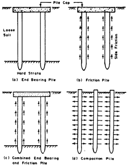
  • A pile that supports the load of a group is named an impression pile or foundation pile. Such pile either drive its support through comparatively softer strata and tests o its tip on a hearth or unyielding strata like dense sand, gravel, or rock
  • It derives the foremost of the carrying capacity from the resistance of the stratum at the tip of the pile. Such piles square measure known as finish bearing or purpose bearing piles,
  • When no exhausting or unyielding firm stratum is accessible inside an inexpensive limit and therefore the friction developed thanks to close soil is adequate to support the pile, the pile is named a friction pile. Now and then the pile is also supported by finish bearing and friction at the same time.
  • A foundation pile could act alone as an associate degree finish bearing pile like column, with or while not very little skin friction. it should conjointly act either as a column in the higher half and friction pile in the lower portion or as a friction pile for a full length.
  • Builder's Engineer: DEEP FOUNDATIONS: Pile Foundation.

    Fig no. 4 Deep foundation


  • The principle perform of the pile is to eliminate excessive settlement to attain the specified bearing capability through the medium of either finish bearing or skin friction or a mix of each, and to compact cohesion, fewer soils, by displacement, thereby up the bearing capability of the soil.
  • Piles square measure used wherever the soil is plain improper for unfolding footings line rescued grounds.
  • Piles are used for reaching a foundation level for bridge piers in a very firm stratum on the far side the boundaries of scouring, to make protecting frameworks like fenders, and to act as anchorages against lateral thrusts and vertical uplift thanks to fluid mechanics pressure or overturning movements.
  •  


    Methods of pile forming

    1. Pile driving

    2 Pile driving hammers

    3. Jetting of piles

    4. Pile driving by vibration

    Pile Driving
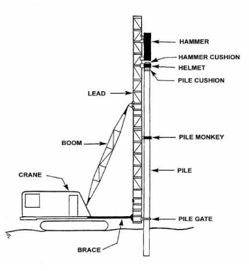
  • To install prefabricated and a few kinds of solid in situ concrete piles, the procedure is to get rid of or displace the soil. Displacement is the usual methodology and will be accomplished by driving, pushing, or jetting-
  • Driving, the foremost common methodology, consists of taking a pile or casing and forcing it to an exact position within the ground with none previous excavation.
  • DEFINITION:  Piles area unit is typically driven by mean of a hammer supported by a crane or by a special device known as a machine.
  • The machine consists of a try of vertical guides called leads among that hammer is command for guiding throughout its operation. The leads will sometimes guide the driving cap. The leads area unit carried on a frame of the tower in such some way that they'll be supported during a vertical or in an inclined position for driving batter piles.
  • Chapter 3 - Installation Equipment - Pile Buck Magazine | Installation,  Construction equipment, Construction machines

    Fig no. 5 Pile driving


  • Where it's inconvenient or uneconomical to use pile false or suspended or hanging leads area unit helpful. They carry with it a try of leads braced at the side of short affiliation and area unit command in position by guy ropes or suspended from a jib of a crane. The swinging leads area unit is called pendulum leads.
  • At times the tower itself may be tipped back or forward for driving rake piles. The chassis provides conjointly for hoisting engines, steam boilers, winches, etc. The assembly is either mounted on a base appropriate for operation ashore, on a barge, or a car. The rigs used ashore could also be of skid kind or track pile drivers. The mounting can also swivel on the bottom.
  • At present, pile drivers area unit nearly universally of steel construction and vary from ten m to twenty-five m high to elaborate frames of twenty-five m or a lot of tall, with extension booms, and capable of full rotation and backward or forward raking.
  • A recent trend is towards light-weight and simply movable mast-type frames of tubular steel. No matter could also be the kind it's essential to make sure that pile frame remains in its correct position throughout the driving or tilt might end in dislocation of the leads is allowed.
  • Alignment of the frame conjointly must be checked to make sure that frame isn't subsidence throughout driving Settlement of frame throughout provides rise to serious risk of breaking pile.
  •  Pile Driving Hammers

  • Hammers used for driving purpose area unit of common varieties like drop press, single acting or double acting steam hammers, and diesel hammers.
  • DEFINITION:  In the past pile drivers were equipped with hammers that fell from the highest of the leads onto the highest of a pile and area unit called drop hammers.
  • Drop hammers area unit solid plenty of forged iron deliberation from 1to To four tones; fitted with lugs for sliding within the lead and with a pin close to the highest for the attachment of the rope or of the nippers that trip once the hammer is at the highest of the leads.
  • Single-acting steam or compressed gas hammer consists of a colossal weight within the variety of a cylinder and also the steam of compressed gas raises it the fastened connecting rod.
  • At the highest of a stroke at the controlled height the steam or air is stopped and also the cylinder falls freely on the pile helmet or driving cap. The most height of a drop is regarding one.35 m and also the hammer may be operated at a rate of up to forty-five strokes per minute. this kind of hammer is kind of appropriate for driving concrete piles
  • CG_6028] Single And Double Action Diagram Free Diagram

    Fig no. 6 Pile driving hammers


  • In associate degree automatic or double-acting hammers, a lighter mass isn't solely raised however conjointly driven down by A powered tend
  • They range in ram weight from ten kilos to 2000 kilo or 8) and area unit designed to impart a speedy succession of blows to the pile. They keep the pile and also the encompassing ground during a constant state of motion so that pile is jolted into the bottom
  • They are effective in sands and gravels however not in stiff clays. Sometimes aside from light-weight hammers, they're operated with steam.
  • This type of hammer is with a restricted drop may be used while not leads. Double-acting hammers of sunshine kind area unit appropriate for timber and also the heavier ones for steel piles.
  • Except for floating rig ought to} be arranged that the pile hammer should be as significant as potential,
  • With inadequate weight giant drops area unit used that area unit quite doubtless to break the pile,
  • It is counseled that a hammer weight mustn't weigh but a third of the pile and preferred be 1/2 the burden of the pile. A study of the stresses in concrete piles (precast) has indicated that the foremost likely conditions of driving area unit obtained by employing a significant hammer and a soft head cushion
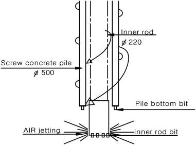
  • JETTING OF PILES

  • Often whereas driving sizable amount of pile through sand and gravel deposits they meet with nice resistance which can harm piles
  • As another to driving water running could also be adopted beneath such circumstances. Jetting is ineffective in the firm to still clay or any soil containing abundant coarse gravel, cobbles, or boulders and in heavily water charged ground.
  • Typical running arrangements area unit illustrated within the jet or jets ought to be thus positioned that the discharge of water is simply below the toe of the pile, permitting the pile sink beneath its weight or if necessary by light-weight driving
  • Test driving or loading of jetted piles mustn't be administered till a minimum of 2 days once the jet is withdrawn.
  • Implementation of Noise-Free and Vibration-Free PHC Screw Piles on the  Basis of Full-Scale Tests | Journal of Construction Engineering and  Management | Vol 139, No 8

    Fig no. 7 Jetting piles

    Pile Driving by Vibration

  • In pile driving the pace with that, the pinnacle is affected is a lot of necessary than either the burden of the pile hammer or the space through that it's been born
  • With freshly developed machines blows may be delivered to the pile cap a hundred to a thousand times as may be delivered by a standard pile rig.
  • Besides its greatly improved potency, the new system is comparatively silent operational.
  •  


    Key takeaways

    Method of pile forming

  • Pile driving - Piles area unit typically driven by mean of a hammer supported by a crane or by a special device known as a machine,
  • Pile driving hammer - In the past pile drivers were equipped with hammers that fell from the highest of the leads onto the highest of a pile and area unit called drop hammers.
  • Jetting of piles
  • Pile driving by vibration
  •  


    Building structures to be supported on pile foundations square measure of the framed kind and individual column footings square measure supported on a bunch of piles.

  • Large teams of vertical piles or with vertical and raked (inclined) piles could also be accustomed to support bridge piers, wharf walls, holding walls, etc. In terribly rare cases singular piles square measure used. It is, therefore, necessary to understand the behavior of piles in the cluster, and therefore the arrangement of piles in an exceeding cluster should be done per their kind like finish bearing or friction piles and whether or not formed or forged in place kind.
  • Individual reactions of the piles could dictate pen the spacing of pie Pies could also be spaced with varied spacing for getting equal pile reaction.
  • The bearing capacity of a pile cluster is a smaller amount than the capability of a single pile increased by the member of piles within the poop
  • The safe style capability of a pile in an exceedingly pop, therefore, is obtained by exploitation applicable face relying upon whether or not the piles square measure finish bearing, and therefore the strata on that they bear, a friction piles.
  • The number of piles and their spacing is then promptly determined. If the whole space lined by the groups is a smaller amount than concerning one 0.5 the realm lined by the structure, individual pile caps square measure provided for every each and if it's larger a pile-supported raft extending over a full ocean of the structure is provided.
  • In the case of the raft, a settlement of but 5 cm is not thought-about harmful once the overall arrangement of the heaped-up foundation is complete the individual piles is designed, taking into consideration handling stresses driving senses and therefore the stresses once the pile is in action.
  • Normally just in case of finish bearing piles driven to rock or similar firm strata, the gross load to be supported by the cluster decides the number of piles in an exceedingly cluster per the quality or designed load-carrying capability of the piles
  • It may be seen here once more that the carrying capacity of piles might not be the same as individual capability increased by the number of piles within the group. it's been verified by theory and field tests
  • The reduction in worth per pile depends on the scale spacing and length of piles and their variety within the cluster
  • The reduction issue which can be employed in such cases is additionally referred to as potency.
  • There square measure some empirical equations referred to as "Efficiency equations that square measure indicated below.
  •  


    Pile driving brings concerning changes in properties of each sandy and clayey soils Compaction results from displacement in non-cohesive soils. Cut resistance shows Associate in Nursing increase, each in non-cohesive and cohesive soils

    Following effects are ascertained

    1. It causes compaction of loose sandy soils to a radial distance of two to three times pile diameter, D closes the pile and concerning a pair of times, the diameter below the tip takes place. Subsidence happens as a result of compaction. Soil compaction will increase pile capability.

    2.  Re mould of sensitive clays leads to a loss of strength within the close soil upto a radial distance of D (upto ninetieth of strength is regained by impact in around thirty ten fifty days) A zone of thickness D on the far side re mould zone gets consolidated.

    3. Shocks throughout driving might cause a physical change of saturated fine sands and silts.

    4.  Surface heaving takes place in dense sandy soils thanks to the loosening impact of vibration and because of the plastic flow of soils.

    5. Squirting will have a prejudicial scouring effect on non-cohesive soils below existing neighboring structures and might cause the fast sand condition.

    6. Concretion of soils behind holding walls increases the lateral pressure.

    7. Displacement piles behind holding walls might cause lateral soil movement and develop passive pressure.

    8. Piles additionally get broken because of the following

    (a) Overdriving or improper driving

    (b) Deviation from alignment

    (c) Use of defective piles

    (d) Obstruction of boulders.

    9. The piles should be protected at high and tip by soft pile cap and dolly at high and shoe at the tip.


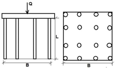
  • The ratio of resisting capability of pile cluster to a total of individual capacities of piles during a group is termed as group efficiency
  •  Group efficiency of friction piles in clays is usually
  • <1, whereas for sands it is > one

  • It group capability > total of individual capacities due to density impact of piles driven in sandy soil
  • Pile driving causes an increase in shaft resistance thanks to an increase in lateral pressure and an increase within the up resistance thanks to the increase in the angle of friction
  • For bearing piles (bearing on laborious soil /rock) group efficiency pressure bulbs don't overlap.
  • Calculate Capacity of Pile Group and Efficiency

    Fig no. 8 Efficiency of piles drive

    Group efficiency

    = Q g/N Q p

    Where Q g = group capability

    N = No. of piles

    Q p = single pile load


    For friction piles, cluster potency n is often as high as a hundred% for the spacing of piles > 5D and low as fifty-five you take care of spacing <2.5 D. whereas spacing > 4.5 D is uneconomical.


    There is no precise methodology for estimating the settlement of pile teams. Therefore, Associate in approximate methodology is mentioned

    Pile groups in Cohesive Soil
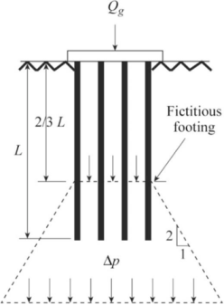
  • The settlement of pile clusters in preponderantly cohesive soil is given by the addition of the immediate elastic settlement and long-run consolidation settlement of the under the soil.
  • The procedure for scheming these settlements square measure almost like that for raft foundations with acceptable depth corrections
  • Definition of Settlement Of Piles In Clay | Chegg.com

    Fig no. 9 Settlement of piles group for cohesive soil

  • However, it's necessary to see the load distribution around a pile cluster to get the dimensions and depth of the equivalent raft from that the settlement is to be determined.
  • Accordingly, total load, Q is assumed to urge distributed from the foundation level at a slope of 4:1 up to the depth of imagined raft at depth 2D f/3
  • Here, the dimensions of the imaginary raft become ( B+ Df /6)
  • (L + Df/ 6). Thereafter, the load is assumed to urge distributed at a slope of 2:1 into the underlying strata,
  • If the pile group passes through a weak stratum to underlying arduous stratum, the load is assumed to unfold at a slope 4:1 on a similar raft at a depth 2 L/3, wherever L is embedment of the pile within the stiff stratum
  • Thereafter, a selection of 2:1 is also followed. For a finish bearing pile, the load is assumed to urge transferred to a similar raft at the extent of pile tip with none dispersion through the higher strata.
  • It is, therefore, necessary to see the compressibility characteristics of the soil below the depth 2 Df /3. The settlement of the pile group might then be c. located within the usual manner.
  • (a)  Immediate settlement

    S I = q n­ B/E (1- 2) I p

    Where q n, = net pressure on the equivalent raft at depth2Df/3,

    B = breadth of the equivalent raft at depth 2 D f/3

    = Poisson's quantitative relation of soil below the depth equivalent raft

    E = coefficient of elasticity of the soils below the equivalent raft

    = (500 - 1000) C u

    I p = influence constant, f(L/B), and

    = depth correction factor f (Df /B, L/B)

    (b)  Consolidation settlement

    The consolidation settlement of the pile group is obtained from the quality equation,

    S c = [(C c/1 +e o) H log (P o + P/Po)]

    S c = (∑ m v p H)

    Where, C c/ (1 + e o) and m, square measure severally the compressibility index and therefore the constant of volume decrease for the suitable stress level of the relevant strata.

    H is that the thickness of strata,

    P o and p square measure the unmoved vertical effective stress and therefore the increase of stress within the various strata, and

    AND square measure severally the depth and pore-pressurecorrection factors.

    to know the effective depth of soil below the cluster, the simplest methodology is to see the strain increment quantitative relation p/p, at completely different depths and think about the depth of soil that p/p> zero.1.

    Pile group in cohesionless

  • Pile foundations in sand don't seem to be expected to endure considerable settlement thanks to the low sponginess of medium to dense, wherever piles area unit sometimes terminated. Still, if necessary, the settlement of pile teams in granular soil could also be determined by exploitation equivalent strategies as given for raft foundations.
  • The load distribution within the soil and also the equivalent strategies raft idea planned for cohesive soil may be adopted to get the pure mathematics of the matter to be solved
  • H = s q u / [N 0.81 (1 +0.4 D f/B)]

    Where H = settlement

    s= settlement constant,

    q u = average pressure on the equivalent raft,

    N = average SPT worth over a depth 2B below the muse level or D s if the depth of cohesionless soil is a smaller amount than 2B.

    Df = depth of equivalent raft, and

    B = breadth of equivalent raft.

    The settlement constant, s vanes with Df/ B


    Key takeaways

    Settlement of piles –

    Piles group in cohesive soil

  • Immediate settlement - S I =
    q n­ B/E (1-
    2) I p
  • Consolidation settlement - S c = (∑ m v
    p H)
  • Piles group in cohesionless soil.


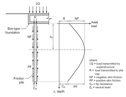
  • If driven or bored piles are put in during a compressible soil or a freshly placed filling, consolidation of soil develops drag AN the piles because of relative movement of soil w.r.t piles leading to reduction of pile masses termed as negative skin friction F fatless is downward drag performing on the pile because of downward movement of encompassing compressible soul relative to the pile.
  • Criteria for the design of friction piles subjected to negative skin  friction and transient loads

    Fig no. 10 Negative skin friction

  • As soil consolidates earth fill moves downward developing friction forces AN perimeter of pile tending to hold pile more into the ground
  • Fn can also even be developed by lowering of well water, increasing effective stress inflicting consolidation of soil, and resultant settlement and friction force being developed on piles.
  •  

    Determination

    The magnitude of F n is determined as

    Fn =Q s (kin resistance) = A s f s

  • For cohesive soils, F n = p L p S u = (π D) L p S u
  • Where p = Pile perimeter π D

    D p or Lp = Length of the pile at intervals compressible layer

    Fs = S u =Un drained shear strength of compressible soil

    2.     For granular soil

    F n = ½ L p2 p k tan <= tan

    K = coefficient of lateral pressure

    = unit weight of soil

    3.     For pile group

    (Fn) g= N (F n) 1

    (Fn) g= c L p p + L p A

    (Fn) g= c L p +p L p A = L p [c p + A]

    Where A = area enclosed in perimeter p of a group of piles


    Measure to minimize F n

    Prevention:

  • To attenuate this impact, pile spacing ought to be S25 D as reducing pile spacing reduces movement of soil with respect to piles, as a result of the pile cluster acts as one unit and negative skin friction is developed solely on the edge
  •  Negative skin friction F n is reduced in bored piles if the casing is employed quickly throughout driving.
  • Negative skin friction in form piles is often reduced by painting the pile surface with hydrocarbon.
  •  

    Key takeaways 

  • For cohesive soils - F n = p L p S u = (π D) L p S u
  • For granular soils - F n = ½ L p2 p
    k tan
    <= tan
  • for pile groups –
  • (F n) g= N (F n) 1

    (F n) g= c L p p + L p A

    (F n) g= c L p +p L p A = L p [c p + A]


    Single pile

  • The end bearing pile motives its entire support the tip whereas it's thought of that the friction pile is sustained by a cone of soil whose enlarging base extend below the tip of the pile to such level that the intensity of the load transmitted by the cone at the bottom is simply adequate the bearing capability of the soil at that level.
  • The end bearing pile is primarily a column that supports a load at its high and in its turn bear on a firm stratum at and close to its tip
  • Naturally, such pile ought to be robust as a column, and la tip mustn't yield below crushing stress
  • Such pile may perhaps have an even cross-section throughout its length to provide it strength as a column and to produce an outsized bearing space at its bottom
  • Such pile seeds lateral still as vertical support. If it's long it's going to buckle and this buckling cannot guitar place unless the pile moves aside the encircling soil
  • In the case of friction pile, the magnitude of the coefficient of friction for the contact surface of the soil and pile depends principally upon the properties of the soil, and therefore the surface of the pile.
  • The cutting off resistance of the encircling soil against aiding upon itself is equally necessary because the resistance
  • If the piles are driven through compressible fill or any soil showing considerable consolidation, settlement of the bottom causes negative skin friction
  • In terribly soft soils, consolidation settlement of the bottom could end in a downward drag on purpose bearing piles. Negative skin friction should be allowed for once considering the issue of safety on the last word carrying capability of the pile
  •  

    Double piles

    End bearing piles

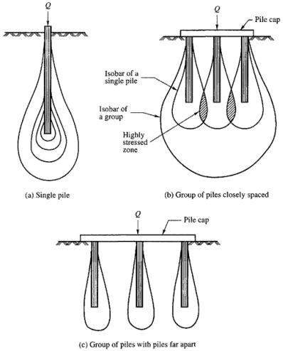
  • In the case of finish bearing piles, the pressure distribution takes the shape as in a very cluster of finish bearing piles driven along there would be overlapping of pressure bulbs.
  • It is not sufficient to confirm that pile are resting on a powerful layer at a selected depth however it should be seen that the strata at a lower place the bearing layer don't seem to be themselves too weak to hold the extra load nor too compressible that the structure is going to be vulnerable by differential settlements.
  • Friction piles

  • In a group of friction piles, things are completely different. Because of the overlapping of the cones of pressure distribution and therefore the areas of soil stricken by individual piles, they'd be below the individual or wide separated piles.
  • When in a very group, friction miles are used for an edge bulb of pressure overlap, and that they are amalgamated into an outsized bulb for the complete group and thus the full bearing worth of a bunch of friction piles has no direct relevancy the carrying capability of a personal pile itself.
  • The settlement is often dish formed with most loads at the center. Once piles bear on compact sand or gravel, with no underlying clay, the settlement would be roughly identical as would get with a raft at the extent of the tip of the piles. If the pressure exerted by piles resting on firm sand or gravel on underlying beads of clay exceeds the pre-consolidation pressure settlement is probably going to continue for several years at a decreasing rate and should be the maximum amount as thirty cm or a lot of, although the issue of safety is adequate
  • The group of piles in clay acts as a floating cluster once piles are driven in clay the displacement of soil leads to a just about re-mould of the clay and heave of the bottom surface. As a result of heave which can be the maximum amount as seventy-five cm finish bearing piles is also raised.
  • Bored and 'H' section steel piles cause a minimum of soil displacement. Wherever finish bearing piles penetrate through compressible strata into stiff clay, settlement takes time to develop because of skin friction and slow method of Consolidates particle in clay. k is, therefore, not suggested in-tuned piles in a very bed of clay. Decomposed bedrock typically possesses identical characteristics as that of the clay.
  •  A structure subjected to vibrations is probably going to settle when the muse soil is cohesionless.
  • Consequently, pile driving could cause settlement of adjacent structures supported on sand; a lot of notably once sand is loose.
  • Builder's Engineer: NUMBER AND SPACING OF PILES IN A GROUP.

    Fig no. 11 end bearing and friction piles with pressure bulbs


    Classification

    The foundation piles are principally classified supported following criteria

    (a) Material of construction Timber, steel, concrete, composite, etc.

    (b) Cross-section Circular, hexagonal, square, I section, H section, pipe, etc.

    (c) Form: cylindrical, tapered, beneath reamed, etc.

     (d) Mode of load transfer Bearing, friction, tension, etc.

    (e) Technique of forming per cast, Pre stressed, solid in place government agency.

    (f) Methods of installation: Driven (Hammer, squirting or vibration), Bored (cased or uncased), Inserted (jacked, pushed, or pre excavated)

    Few different types of piles are discussed here

    (g) Function or purpose

  • vertical support: friction wed bearing piles
  •  Lateral resistance: batter piles, sheet piles
  • Anchoring: beneath reamed and screw piles
  •  Compaction t: Displacement piles
  •  Pre consolidation stone piles and und drains
  •  

    Classification of piles

    1. Timber piles

    2. Metal piles

    3.  Precast console and

    4.Driven and cal-in place-concrete piles

    5. Bored and cast-in-place concrete

    1 Timber Piles

  • Centuries ago man used the trunks of trees and piles to daring up the waterfront and different structures. Piles are conductor from the trunk of trees alter trimming the branches and typically removing the bark and will or might not be treated with a preservative
  • The tip could also be pointed or sq. having a diameter from twelve to twenty-five cm and therefore the butt finished sq. with a chamfered edge and will have its diameter from thirty-five to S0 cm.
  • The length varies from six to fifteen m or so
  • Timber piles done stand up to the stresses because of onerous driving which can be needed for penetrating through an extremely resistant layer
  • Damage to the tips or points could also be reduced by exploiting iron or steel shoes. However, the danger of breaking the pile or damaging the butt ty rending or broom is reduced by limiting the energy and variety of the blows of the pile driving hammer
  • Normally the operating load on timber piles is restricted to concerning twenty-five tone sand, in several localities, to still less price
  • Wooden piles last indefinitely once settled below permanent formation, however, they're subject to decay higher than water or in the zone of unsteady water level, woodpiles are organic and subject to the attack of the assorted bacterium, boring organism, and fungi by keeping them for good below here we tend to be for the most part strangled and therefore the lifetime of the pile prolonged indefinitely.
  • A considerable degree of length is achieved by treating wood with creosote struggling
  • But generally driving of timber piles into gravel or soil containing boulders could damage the pales seriously so treated portion la crushed or cracked to such associate extend that decay of interior could come about
  • 2.  Metal Piles

  • Amongst metal piles are enclosed those who rely primarily upon steel for resistance to longitudinal and crosswise stresses
  • However, the steel pile is that the time wont to denote the rolled steel H' section. Significantly for fulfilling the requirement of very long piles with high bearing capability, concrete stuffed steel tubes and H section steel piles are largely utilized in the USA
  • The shell or however piles are composed out of sheet piles The pipes used for such purpose home in diameter from twenty-five cm to seventy-five cm diameter associated have shell thickness varied from five millimeters to twenty-five millimeter and are driven either with an opened or closed.
  • Steel H piles penetrate into the bottom a lot of without delay than different varieties as a result of the displaced comparatively very little material.
  • But the susceptibility to corrosion wants special thought
  • Allowance for corrosion will l: created whereas choosing the thickness of the metal, but corrosion is nota major problem once the pile doesn't extend higher than the H2O table
  • Precast concrete piles

  • Precast piles are those that are mould to an everyday kind and once hardening is handled and driven like timber or steel piles. An obstacle of formed piles is their nice Semitic deity driving stresses.
  • But different varieties like solid in situ or pre stressed concrete piles need a lot less steel than the precast concrete piles
  • Precast piles are substituted by other forms of concrete piles where doable. However, formed concrete piles are ideally utilized in docks, piers, concrete trestle bents, and similar structures wherever some of the pile remaining higher than from close soil and wherever goodly bending moment is probably going to develop within the pile
  • They are additionally appropriately employed in soil conditions like waterlogged sand which can be unfavorable to cast-in-place pilesand in conditions wherever high resistance to lateral forces is needed.
  • The design of a formed pile is ruled by the necessity to grant adequate strength to resist the stresses thanks to handling, lifting, driving, and ultimately the load to be borne by the pile
  • The cover to the reinforcement mustn't be but four cm of concrete and once exposed to ocean water or different corrosive influences be not but five cm.
  • The design of the pile willbe going to be additionally plagued by the purpose or points at that it's upraised.
  • Splicing of an extra length on formed concrete piles is settled by striping the head and overlapping the longitudinal bars for a distance not but forty diameters. The splice should develop adequate strength before driving is recommenced
  • Pre stressed concrete piles supply advantage beneath sure circumstances.
  • With them cracking is eliminated and therefore the chance of corrosion of reinforcement is reduced
  • Pre stressed concrete piles are typically created by the pre-tensioning method. Upto 40 cm. sq. section piles are created with a solid section of concrete. Larger piles are economical once created hollow
  • Pre stressed concrete piles are handled and driven in a similar manner to standard formed concrete piles.
  •  

    Key takeaways

    Classification of piles

  • Timber piles
  • Metal piles
  • Precast console
  • Driven and cal in place concrete piles
  • Bored and cast in place concrete
  •  


    References

  • P purushothama Rag: soil mechanics and foundation engineering; Pearson education
  • Shenbaga R Kaniraj: design aids in soil mechanics and foundation engineering
  • Gopal Rajan, Rao ASR; basic and applied soil mechanics

  • Index
    Notes
    Highlighted
    Underlined
    :
    Browse by Topics
    :
    Notes
    Highlighted
    Underlined