Back to Study material
FD

Unit-4

Introduction, shapes and characteristics of wells


INTRODUCTION SHAPES

CAISSONS

Introduction:

French word caissons mean that too and might be open at either finish on at one end. Such box with shut bottom may be prefabricated onshore so floated to the required site and is allowed to seat on a prepared base

  • In the case of caisson with each end open is allowed to sink thanks to its large loading and conjointly by removing soil within the box.
  • Such box when-filled with sand becomes large and is capable of resisting horizontal trust thanks to waves or impart of ship or thanks to the slender significant wind, etc
  • When the depth of water is high. Pile being slender, is unable to resist significant thrust. In such cases, the caisson foundation offers a higher answer
  • Types of Caissons

    There are three sorts of caissons

    Types of caisson

    (a) Box caisson

    (b) The open caisson

    (c) Pneumatic caisson

    (a) Box Caisson
  • Thus it a water-tight vessel that is open at the highest and closed at all-time the box might be created out of timber, concrete, or steel.
  • The box is made on the watercourse bank. Then it's floated and towed to the position. It is then crammed with dead load and done for at the sight wherever it is a foundation
  • The box sort screen l appropriate for shallow depth foundation and waste the causative forces don't seem to be extended.
  • Caisson Foundation - Construction, 5 Types and Advantages

    Fig no. 1 Box caisson


    Advantages of Box Caisson

    1. Box caisson may be provided just in case alternative sorts prove pricey or don't seem to be possible.

    2. It may be extended up to massive depths.

    3. It may be created onshore and floated to the place installation.

    Disadvantages of Box Caisson

    1 It needs exhausting strata for the bearing, therefore appropriate if such stratum is offered at shallow depth

    2 Provision is needed for defense from scouring.

    3. Progress is delayed if there's an obstruction like a log or boulders deep down of the caisson.

    4. Inspection and excavation deep down is tough and needs different for such work

    5. At bearing strata concrete scale provided might not be satisfied being placed beneath the water

    (b) Open Caisson
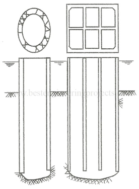
  • Essentially it's a cylindrical structure made from brick R.CC or steel created at the website with open bottom and high. The structure is penetrated at the location and once it reaches the specified location, wealthy flowable concrete is provided to serve on plug/seal.
  • When seal fourteen utterly cured, water in caisson is pumped up out so, all-time low is closed, and interspace is crammed with appropriate material like sand, etc. so the highest is additionally closed by concrete. On the highest either pier or abutment is then created.
  • Caissons | Types of Caissons | Advantage of Caissons

    Fig no 2 Open caisson


    Advantages of open caissons

    1. The caisson may be created to nice depths.

    2 the development value is comparatively sawed.

    Disadvantages of Open Caisson

    1. The clearing and scrutiny of the bottom of the caisson cannot be done

    2 Concrete seal placed in water won't be satisfactory.

    3. The speed of progress is going to be delayed if boulders are met throughout the construction.

    (c) Pneumatic caisson
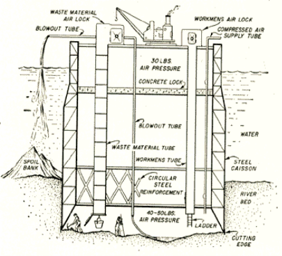
  • This type of caisson in additional suitable once the extent of water within the watercourse is sufficiently high and it's needed to travel deep to urge appropriate strata having the requisite bearing capability.
  • This type-in primarily well with an open bottom and closed high in between these 2, gas pressure is maintained so that water doesn't get in excavation, and concreting work will endure with ease.
  • The operating chamber at the all-time low of the caisson is unbroken dry by ejection water beneath gas pressure. Airlocks are provided at the highest height.
  • The caisson is sunk because the excavation takes. Upon reaching its final depth, the operating chamber is crammed with concrete. For the movement of working person operating bottom one separate passage in provided.
  • For transport of fabric excavated musk etc. A separate passage is provided.
  • Caisson Foundation - Types Of Caisson Foundation

    Fig no 3 Pneumatic caisson


    Advantages of pneumatic Caisson

    1. Management over the work and preparation of foundation for the sinking of caisson higher since the work is finished within the dry condition.

    2 The caisson may be done vertically as careful superintendence is feasible.

    3. The bottom of the chamber may be sealed effectively with concrete because it may be placed dry.

    4. Obstruction to sinking such as boulders east northeast maybe considerd.

    Disadvantages of gas Caisson

    1 Construction value is kind of huge amount.

    2 The depth of penetration below water is restricted to concerning higher costs are on the far side the endurance of the shape.

    SHAPES

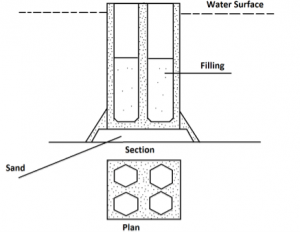
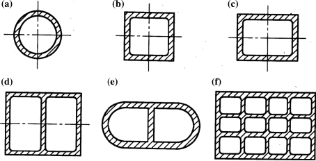
    Caissons may be completely different shapes
    Design of Open Caisson Structures | SpringerLink

    Fig No 4 Shapes of Caissons


    Circular form

  • This form covers most space with the least circumference. Sinking is comparatively straightforward as there aren't any comes and offers equal distance altogether directions.
  • If the dimension of the pier to support the superstructure say one-lane road bridge is little, then this form is appropriate. But because the range of tracks increases, providing diameter adequate the dimension of track beam uneconomical.
  • In such a case, the twin circular dumb well is Double D is a lot of helpful. These shapes become unsuitable if the number of tracks increases.
  • Further, the diameter of larva will increase, in obstructs water approach of the watercourse.
  • Redaction in water approach cause in the speed of currently of them by increasing the danger of scouring and therefore leading chain of larger depth.
  • Rectangular form to wait Shuttering material for formed or forged in place RCC caisson. Sinking caisson of this form is tough, it introduces comer stress.
  • Pickets choose rectangular form are used, If the depth of ion is less.
  •  Caisson Diseases

  • Working beneath compressed gas for an extended length lead to abortion of atomic number 7 in conjunction with O by the tissue fluid of the person.
  • Oxygen is soluble in blood however atomic number 7 is suspended from within the blood since it's not soluble in blood. Once decompression in undertaken the atomic number 7 probably to be released is that the sort of bubbles.
  • These bubbles if blocked in joints cause pains within the Joint even creating them useless.
  • If the bubbles are arrested within the region of the spinal cord or heart, it will offer to paralysis or heat attack, ensuing even in death. This development is termed caisson diseases.
  • So that caisson diseases mustn't occur, precautions taken are a medical chamber is provided at the top of a caisson.
  • Before going into the operating chamber deep down working person must it into the medical chamber at the bottom layer, wherever the pressure from air pressure to operating pressure la bit by bit enlarged.
  • Similarly, whereas getting back from the operating chamber, the working person sits in the medical chamber, wherever pressure is bit by bit ablated from operating pressure to air pressure.
  • Thereafter only working person is permissible to travel out.

  • One person, one shift daily of eight hours is to be meticulously followed the particular operating in compressed air should not exceed four hours.
  •  A ready-bodied person, with no tendency of high blood pressure, ought to solely be used.
  •  The compression and decompression ought to be slow.
  • Stand arrangement of mechanical device and decompressor ought to be there for an emergency.
  • Well ventilated and sanitary arrangement ought to be there within the medical lock.
  • A correct medical facility should be on the market at the worksite.
  • CHARACTERISTICS OF WELLS

    Well foundation

    The art of good foundation is renowned to Indians well before the sixteen century since world-renowned Taj Mahal stands on the well foundation.

    Advantages of Well foundation

  •  It will stand giant lateral forces as just in case of piers, aliments, tall chimneys, etc. during a higher manner thanks to rigidity and huge cross-section.
  • It's attainable to look at strata and judge the depth of the institution the well.
  • No dynamic load is concerned throughout the construction of well foundation thence, adjacent structures aren't affected.
  •  

    Key takeaways

    SHAPES

  • Caissons
  • Types of caissons

  • Box caissons
  • The open caissons
  • Pneumatic caissons
  • Different types of shapes are also their like circular, square, rectangular, etc
  •  


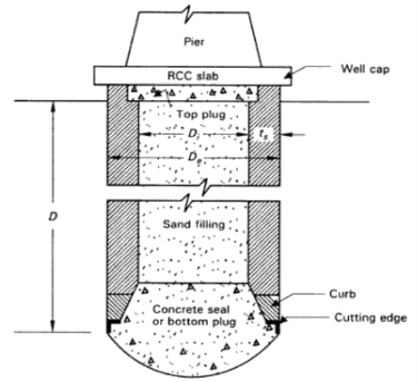
  • Cutting edge
  • Steining
  •  Curb
  • Concrete seal or bottom plug
  • Top Plug
  • Well cap
  • Cutting Edge

  • They perform the innovative is to facilitate simple penetration or sinking into the soil to the required depth. Because it must cross the soil. it ought to be as sharp as attainable, and powerful enough to resist the high stresses to that it's subjected throughout the sinking method.
  • Hence it always consists of an associate angle bracket with or whiles not an extra plate of steel. Details of the curb with cutting edge. Sinking of well with a sharp edge is quick but if strata boulder is met then the sting could get broken.
  • Steining

  • The steining forms the majority of the well-founded and will be made with brick or stone masonry or with plain or concrete sometimes.
  • The thickness of the steining is created uniform throughout its depth. it's thought-about fascinating 'to give vertical reinforcements to require care of the tensile stresses which could occur once the well is suspended from prime throughout any stage of sinking.
  • Curb

  • The well curb may be a transition member between the sharp innovative and also the thick steining. It's therefore tapering in form. It's typically fabricated from concrete because it is subjected to severe stress throughout the sinking method.
  • Concrete seal or bottom plug

  • After the well foundation is undone to the required depth therefore on rest on a firm stratum, a thick layer of concrete is provided at very cheap within the well, usually underneath the water. This layer is named the concrete seal or bottom plug, There is the bottom for the well foundation.
  • This is primarily meant to distribute the hundreds onto an oversized space of the muse and thence is also omitted once the well is created to rest on an arduous rock.
  • Top Plug

  • After the well foundation is undone to the required depth, the within of the well is crammed with sand either partially or absolutely, and a prime layer of concrete is placed. This is often called top plug.
  • The sand filling serves to distribute the load a lot uniformly to the bottom of the well, to cut back the stresses within the stening, and to extend the stiffness of the well foundation.
  • However, as this adds to the burden and cargo transmitted to the muse stratum, the engineer must think about the desirability or otherwise of providing the sand filling from the port of read of bearing power and settlement.
  • The top plug and concrete serve to transmit the hundreds to the base in a uniform manner.
  •  Well cap

    The well cap is a control pad to the construction, which can be a pier or associate abutment. It distributes the construction load onto the well steining uniformly.

    What Is Well Foundation | Component of Well Foundation

    Fig no 5 Components of well foundation


  • Dead loads
  •  Live hundred
  • Impact load
  • Wind loads
  • Water pressure
  • Longitudinal force
  • Earth pressure
  • Force
  •  Buoyancy force
  • Temperature stresses
  • seismic forces
  • Resultant force
  • 1. Dead Loads

    The weight of the superstructures and the self-weight of the well foundation represent the dead hundreds.

    2. Live Loads

    The live hundreds within the case of main road bridges are fixed by IRC. For the style of railway bridges, Indian railways follow-

    The Indian Railway Bridge Rules (1963) are given by research, style, and Standards Organization (RDSO), Lucknow of the Ministry of Railway, Government of India.

    3. Impact loads

    The live hundreds cause impact result and it's thought-about within the style of pier cap and bridge seat on the abutment. Impact results could also be neglected for the elements of the well.

    4. Wind Loads

    Wind loads working on, superstructure and therefore the part of substructure situated higher than the water level are calculated supported "Indian customary Code of following for Structural Safety of Buildings Loading Standard" Wind hundreds act on the exposed space virtually.

    5. Water pressure

    Water pressure is thanks to the water current working on the part of the substructure between the water level and therefore the maximum scour level.

    The intensity of Water pressure on piers parallel to the direction of flow is given by

    P = K v 2

    Where p = Intensity of Water Pressure (N/m);

     V = speed of the water current (m/s).and

    K = a constant, that depends upon the form of the well (maximum 788 for sq. over piers, and minimum 237 for piers with cutwaters and case-water)

    Vis took to be the most at the free surface of flow and 0 at the deepest scour level, the variation is assumed to be linear. The most worth is taken to be v times the typical worth.

    A crosswise force of 2 hundredths of that parallel to the flow is assured to permit for occasion obliquity of flow.

    6. Longitudinal Force

    Longitudinal force happens thanks to rubbing and braking forces. These are transmitted to the substructure in the main through fastened bearing and thru friction on movable bearings per IRC code, a Longitudinal force of W is taken on the free bearing and therefore the balance on the fastened bearing, wherever W is that the total reaction and the constant of friction.

    7. Earth Pressure

    The earth pressure is calculated supported by one in every of classical earth pressure theories by temperature unit or Coulomb. Passive earth resistance of the soil is taken under consideration for the soundness of foundations below the scour level. The result of the live load on the abutment on the planet pressure is taken into account by taking the constant height of surcharge.

    8. Centrifugal force

    A force is taken to be transmitted through the bearing the construction is bowed in set up.

    9. Buoyancy Force

    Buoyancy reduces the effective weight of the well. In masonry or concrete staining 15% of the load is taken the buoyancy force to account for the consistency.

    When the well is supported on coarse and, full buoyancy capable the weight of the displaced volume of water is taken into account for semi receptive foundation, the applicable reduction could also be created supported the situation of groundwater level.

    10. Temperature Stresses

    Longitudinal forces are induced thanks to temperature changes. The movements thanks to temperature changes are partly restrained in beam bridges as a result of friction.

    11. Seismic Forces

    These are to be considered in an applicable seismic zone. It's capable of a W. wherever W is that the weight of the element, and because of the seismic constant. The worth depends upon the Zone and is given in IS: 1893 1975 Indian customary Criteria of "Earthquake Resistance style on Structures".

    It is worth ranges from zero.10 0.08. The seismic force acts through the center of gravity of the element. it should act in any one direction at a time. Separate seismic forces are thought-about on the axis of the pier and crosswise to its.

    12. Resultant Force

    The magnitude, direction, and therefore the purpose of application of all the applicable forces are found for the worst attainable combination. The resultant will be purported to get replaced by constant vertical force W, and lateral forces, P and letter of the alphabet within the longitudinal and crosswise direction of the pier, severally. The action of letter of the alphabet is going to be additional crucial within the thought of lateral stability of the well.


    1. Preparatory work

    2 Construction of the sand stand

    3. Laying of curb

    4. Providing shuttering reinforcement and concreting

    5. Well staining

    6. Measures to increase the speed of sinking

    1. Preparatory work

    Generally, the construction of well foundation commences in the summer season when there is less water in the river. It is economical to locate piers and wells in the dry area since it reduces to some extent the cost of dewatering, timbering, etc. In such case, open excavation upon half a meter above subsoil water level is carried out.

    2. Construction of the sand island

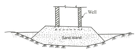
    At the desired location if the depth of water is less than 5 m, then a sand island is created to facilitate the sinking of well as it is easier to control vertically of well by sand island. The size of the island is adequate to accommodate the well and to have some working area around.

    3. Laying of curb

    If the depth of water is less than 5 m, the curb is laid on a sand island constructed. However, if it is more, then curt is precast on the store and then floated to site. The cutting curb is supported on wooden sleepers laid on the sand island while the cart is placed below the curbin by one. By providing sleepers a load of curt is distributed uniformly.
    Sinking of the Well Foundation | Bestengineeringprojects.com

    Fig no 6 Sand island for sinking a well

    4. Providing shuttering reinforcement and concreting

    Outer stuttering in the form of eel or timber is provident Inner battering content of brick masonry requirement for curb is placed in a position much vertical hand has at least of 2 projections In between shuttering cement concrete of adequate workability is provided without any joint and cured. Thereafter the sleeper below the curb is removed and the well is allowed to sink.

    5. Well steining

    1.5 m steining constructed and is allowed to sink after attaining sufficient strength. The probability of the well is checked from time to time and suitable connection measures are taken. In the initial stages, steining is cast at a height of 1.5 m and later on, these can be increased to 3 m to overcome frictional resistance.

    6. Measures to increase the speed of sinking

    For safe and curly sinking of well, the following measurements are taken

  • Maintaining verticality
  • Tilting well will cause unequal stresses and the speed of sinking will reduce

    2.     By removing the soil uniformly

    Vertically speed can be maintained

    3.     Jetting of water

    Inside and outside the periphery of will reduce frictional resistance this is attained by jetting water through pipes with nozzles all along water periphery.

    4.     Providing kentledge

    Suitable platform resisting on steining is constructed and on this platform kentledge in the form of RSJ /heavy block plates sandbags etc are placed to overcome frictional resistance.

    5.     Chiseling and Light blasting

    In Case, during the sinking of well meets a boulder, which can be taken out by grab or which can obstruct the cutting edge, divers send down and used to call it by ordinary chisels and hammers. This was not successful a hole is to be drilled into the boulder by ordinary chisel und hammer and about I/4 charge (gelignite) is to be deposited is it by divers. The blasting of the charge is to be done electrically from the top of the well with 12 volts battery. This makes the boulder and facilitates the sinking operation.

    6.     Use of Drop Chisel

     When soil strata are hard the excavation operations of the dredger could be aided by the use of a drop chisel The chisel could be just double sections welded together and strengthened by rails co either side of the sections. The chisels should have pointed and at the bottom and a bole sear the top. Through a power winch and steel wire rope, the chisel which may be 3 meters long is held and dropped from a height.


    Key takeaways

    In the sinking of wells, there are different steps

    1. Preparatory work

    2 Construction of the sand stand

    3. Laying of curb

    4. Providing shuttering reinforcement and concreting

    5. Well staining

    6. Measures to increase the speed of sinking

    Measure to increase of speed of sinking

  • Maintaining verticality
  • By removing the soil uniformly
  • Jetting of water
  • Providing kentledge
  • Chiseling and light blasting
  • Use of drop chisel
  •  


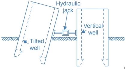
    The tilt of the Well

    Difficulties in well sinking

    Difficulties in well sinking are

  • The tilt of the well
  • The shift of the well
  •  Sand Island
  • Hanging up
  • During the sinking process of the well, the well can tilt. The magnitude of the tilt that can be allowed is 1 in 60.

    The general causes of the tilt of the well

    The general causes of the tilt of the wall are

    (a) Meeting hand strata such as boulder on one side and soft soil such as sand or weak clay on the other side of the well.

    (b) Unequal or eccentric Kentledge.

    (c) Slopping bed given tilt p initial stages of sinking operations.

    (d) Usual rubbing or excavation inside the dredge hole or outside the well.

    (e). The sudden sinking of the caisson. The tilt of the well having once started, it is difficult to arrest it when it is occurring we can only rectify the tilt that has occurred.

    Usual methods for the rectification of tilt

    Methods for the rectification of the tilt

    (a) Control of dredging

    (b) Packing on the low side

    (c) Water Jet method

    (d) The method of wedges

    (e) Unequal loading

    (f) Explosives

    (g) Unequal excavation

    (a) Control of Dredging

  • The edge of the well that has tilted known as the tilted edge needs a cure. Dredging is conducted under and near the tilted edge.
  • This may be done by sending a diver equipped with a chisel and hammer. The diver will conduct underwater operations. The use of water Jet, light blasting, or drop chisel can also be resorted.
  • If proper care is not exercised and unfortunately the dredging of the tilted edge is excessive, well may suddenly heave up. It is difficult to correct the tilt by dredging if the well has gone very deep.
  • (b) Packing on Low side

  • The method is applicable when will sinking is carried out under dewatered condition. Therefore the method is applicable for pneumatic caissons or wells when dewatering is carried out by pumping operations.
  • The sandbags are packed under the tilted portion of the well on the low side after dewatering. After this excavation is carried out on the high side till the well corrects itself.
  • (c) Water Jet technique

  • In this technique water underneath 70 Newtons/cm is forced on the world to be excavated. Forcing it done by pasting the water through a nozzle of twenty-five min diameter.
  • Actually, a diver supplied with, correct helmet holds this nozzle in his hand and dives within the well. He dives close to the leading edge and holds the water jet against the soil encompassing the boulder and therefore loosens it and comes back to top.
  • The loosened boulder is now removed by grab to facilitate sinking.
  • (d) The methods of Wedges

  • Many times forces are often applied to the well by putting a strut against some fixed object driving wedge between them. In case the fixed objects are not available man-made crib wall has to be erected and used.
  • The strut utilized in this technique is thought to have decent bearing space on well and penetrate and cut the exhausting murum or sticky soil. When operative the chisel for some time the set material is taken out by grab.
  •  (e) Unequal Loading

  • Unequal Kenteledge is applied to convey a lot of load on the higher aide This helps in rectifying all.
  • (f) Explosives

  • Small explosives could also be deposited underneath the leanings edge and exploded to loosen the fabric there. When loosening of such material reduced burden is enough to rectify the lean.
  • Shifting and Tilting of Well Foundations

    Fig no 7 Rectification of tilt

    (g) Unequal Excavation

  • In this technique, the open pit is dag on the aspect of the leaning edge and therefore the filling is completed on the other aspect.
  • There is the release of earth pressure towards the leanings edge and increase of earth pressure on the opposite side that thus rectifier tilts.
  • It is incredibly necessary to envision by suggests that of theodolite that the well is sinking vertically.
  • The tilt once started if not checked then the sole recourse left to the engineers is to rectify the tilt that may have occurred.
  • Sand blowing

  • It is a development related to the fast sand condition. Throughout the dewatering of the dredge, hole in sandy strata. if the important hydraulic gradient is cascaded, could also be because of Intense pumping or less density of and stratum, the sand becomes unstable, and there la sharp call in the level of the sand.
  • Sometimes the prevalence is thus sharp that machinery and men operating within the dredge holes area could get ruined it would result in human death.
  • Whenever dewatering operations are being disbursed, care may be taken to ascertain that in no Case important gradient is exceeded.
  • In Spite the ordinary care is taken, whenever the engineers on the sphere feel that sand processing is probably going to occur, well sinking ought to be straight away suspended and bundles of grass, sizable boulders ought to be dump all around this staining to manage and processing.
  • The shift of the well

  • The shift of the well refers to the general lateral displacement of the well is set up. The shift of the well leads to dynamical span length of the bridges and eccentric loading on the pier.
  • Deep well typically don't shift. Even within the cases allow wells tilt could be a lot of pronounced development than the shift of the well.
  • It is tough to rectify the shift and therefore the best means is to require care thus that shift doesn't occur.
  •  

    Precautions to be determined to stop sand processing tilt and shift

    (1). Care to be taken throughout dewatering operations, so that important gradient ne'er exceeded.

    (2) Outer surface of well curb and steining ought to be as swish as attainable.

    (3) Radius of curb ought to be unbroken a pair of to four cm larger than the Suicide radius of well steining.

    (4) Uniform dredging and uniform kentledge.

    (5) Leading edge of the curb to be of uniform thickness and sharpness.

    Key takeaways

  • Difficulties in well sinking
  • The tilt of the well
  • The shift of the well
  •  Sand Island
  • Hanging up
  • Causes of tilt of wells
  • There are different methods for rectification of well given above
  •  


    Introduction

  • Retaining walls area unit comparatively rigid walls used for supporting soil laterally so that it will be maintained at totally different levels on the 2 sides. Retentive walls area unit structures designed to restrain soil to a slope that it might not naturally keep to (typically a steep, near-vertical, or vertical slope). they're accustomed sure soils between 2 different elevations usually in areas of a piece of ground possessing undesirable slopes or in areas wherever the landscape must be formed severely and designed for additional specific functions like slope farming or road overpasses. A wall that retains soils on the backside and water on the front side is termed a groin or a divider.
  • A gravity-type stone wall; A wall for holding in situ a mass of earth or form, as at the sting of a terrace or excavation a wall could be a structure designed and made to resist the lateral pressure of soil, once there's the desired modification in ground elevation that exceeds the angle of repose of the soil.
  • A basement wall is so one reasonably wall. However, the term typically refers to a cantilever wall that could be a separate structure while not lateral support at its prime.
  • These area units cantilevered from a position and rise higher than the grade on one facet to retain the next level grade on the alternative facet. The walls should resist the lateral pressures generated by loose soils or, in some cases, water pressures.
  • Every wall supports a "wedge" of soil. The wedge is outlined because the soil that extends on the far side the failure plane of the soil kind gift at the wall website, and might be calculated once the soil friction angle is thought. Because the blow of the wall will increase, the scale of the slippery wedge is reduced. This reduction lowers the pressure on the wall.
  • The most vital thought in the correct style and installation of retentive walls is to acknowledge and counteract the tendency of the maintained material to maneuver fall thanks to gravity. This creates lateral earth pressure behind the wall that depends on the angle of internal friction (phi) and therefore the cohesive strength (c) of the maintained material, similarly because the direction and magnitude of movement the retentive structure undergoes.
  • Lateral earth pressures area unit zero at the highest of the wall and – in the same ground – increase proportionately to the most price at very cheap depth. Earth pressures can push the wall forward or overturn it if not properly self-addressed. Also, any groundwater behind the wall that's not dissipated by a system causes fluid mechanics pressure on the wall. The entire pressure or thrust could also be assumed to act at third from very cheap depth for lengthwise stretches of uniform height.
  • It is vital to own the correct drain behind the enclosed order to limit the pressure to the wall's style price. Drain materials can cut back or eliminate the fluid mechanics pressure and improve the soundness of the fabric behind the wall. Drystone retentive walls area unit is commonly self-draining.
  • As Associate in Nursing example, the International codification needs retentive walls to be designed to make sure stability against overturning, sliding, excessive foundation pressure and water uplift; which they are designed for a security issue of one.5 against lateral slippery and overturning.
  •  


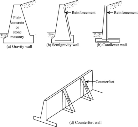
    Gravity wall

  • Gravity walls rely on their mass (stone, concrete, or different serious material) to resist pressure from behind and should have a 'batter' blow to boost stability by leaning back toward the maintained soil. For brief landscaping walls, they're usually made of mortar less stone or segmental concrete units (masonry units). Dry-stacked gravity walls area unit somewhat versatile and doesn't need a rigid footing.
  • Earlier within the twentieth century, taller retentive walls were usually gravity walls made of massive lots of concrete or stone. Today, taller retentive walls area unit more and more designed as composite gravity walls like geo synthetics such as geocell cellular confinement earth retention or with formed facing; gabions (stacked steel wire baskets crammed with rocks); crib walls (cells designed up cabin vogue from formed concrete or timber and crammed with granular material).
  • Definition of Semi Gravity Retaining Walls | Chegg.com

    Fig no 8 Types of walls


    Cantilevered wall

    Cantilevered retentive walls area unit made of an interior stem of steel-reinforced, cast-in-place concrete or mortared masonry (often within the form of Associate in inverted T). These walls cantilever hundreds (like a beam) to an outsized, structural footing, changing horizontal pressures from behind the wall to vertical pressures on the bottom below. Typically cantilevered walls area unit supported on the front, or embrace a counterfort on the rear, to boost their strength resisting high hundreds. Buttress area unit short wing walls at right angles to the most trend of the wall. These walls need rigid concrete footings below seasonal frost depth. This sort of wall uses a lot of less material than a standard gravity wall.

    Diaphragm wall

    Diaphragm walls area unit a kind of retentive walls that area unit terribly stiff and usually watertight. Diaphragm walls area unit pricy walls, however, they save time and house, and thus area unit utilized in urban constructions.

    Sheet pile wall

    Sheet pile retentive walls area unit typically utilized in soft soil and tight areas. Pile walls area unit driven into the bottom and area unit composed of a range of fabric together with steel, vinyl, aluminum, covering material or wood planks. For a fast estimate, the fabric is typically driven 1/3 higher than the ground, 2/3 below ground, however, this could be altered reckoning on the setting. Taller pile walls can be like a tie-back anchor, or "dead-man" placed within the soil a distance behind the face of the wall, that's tied to the wall, typically by a cable or a rod. An anchors area unit was then placed behind the potential failure plane within the soil.

    Bored pile wall

    Bored pile retentive walls area unit designed by grouping a sequence of bored piles, followed by excavating away the surplus soil. Reckoning on the project, the bored pile wall might embrace a series of earth anchors, reinforcing beams, soil improvement operations reinforcement layer. This construction technique tends to be used in eventualities wherever sheath pile could be a valid construction resolution, however wherever the vibration or noise levels generated by a machine aren't acceptable.

    Anchored wall

    An anchored wall will be made in any of the aforesaid designs however conjointly includes extra strength victimization cables or different stays anchored within the rock or soil behind it. typically driven into the fabric with boring, anchors area unit then expanded at the tip of the cable, either by mechanical suggests that or usually by injecting pre stressed concrete, that expands to create a bulb within the soil. Technically advanced, this methodology is incredibly helpful wherever high hundreds area unit expected, or wherever the wall itself must be slender and would preferably be too weak.


    Key takeaways

    Types of retaining walls

  • Gravity walls
  • Cantilevered wall
  • Diaphragm wall
  • Sheet pile wall
  • Bored pile wall
  • Anchored wall
  •  


    A. General

  • Sheeting is driven to a depth comfortable for the passive pressure exerted on the embedded portion to resist the lateral active earth pressures performing on the cantilevered section. To realize the desired passive earth pressure resistance, embedment depths will usually be quite high. Therefore, thanks to limitations on the provision of sure section modulus and its associated prices, cantilevered textile walls are typically sensible to a most height of roughly fifteen feet. (4.6 m).
  • Soldier piles of a soldier pile and insulation wall system are vertical structural components spaced at set intervals, usually half dozen f. to 10 ft. (1.8 m to 3.0 m). A soldier pile and insulation wall additionally derives its resistance from the embedded portion of the wall however, as a result of the upper offered section modulus, bigger excavation depths will be supported as compared to those supported by textile. Cantilevered soldier piles are typically sensible for excavations up to around twenty-foot(6 m) tall.
  • The minimum timber insulation thickness for a soldier pile and insulation wall ought to be determined from the table in Appendix B. taken from Lateral Support Systems and Underpinning.
  • Additional style steering for textile and soldier pile and insulation walls is provided and/or documented in Appendix D.
  • B. Analysis

  • Use either the Simplified technique or the traditional technique for the planning of a cantilevered textile wall. To account for the variations between the 2 ways, the calculated depth of embedment, obtained using the Simplified technique, shall be exaggerated by 2 hundredths. This increase isn't an element of safety. The issue of safety shall be applied to the passive pressure.
  • Use either the Simplified technique or the traditional technique of study for the event of the lateral pressures on a soldier pile and insulation wall. However, as against a textile wall that is analyzed per foot (meter) of the wall, the calculations for the planning of a soldier pile and insulation wall should account for the spacing of the individual soldier piles. To work out the active pressures higher than the dredge line, embody an element corresponding to the spacing within the calculations. to work out the active pressures below the dredge line, embody an element corresponding to the breadth of the soldier pile (for driven piles), or diameter of the outlet (for piles put in excavated holes) within the calculations, to work out the nonviolent resistance of a soldier pile embedded in the soil, assume that cyber web nonviolent resistance is mobilized across a most of thrice the soldier pile breadth (for driven piles), or thrice the diameter of the outlet (for piles put in excavated holes).
  • Both the Simplified and traditional techniques of analysis are printed in the USS Steel piling manual. The Simplified technique is additionally represented in Section five. Retaining Walls within the normal Specifications for road Bridges, Adopted by the American Association of main road and Transportation.
  • C. Constructability

  • Before the analysis, the designer shall value the location conditions and submerged profile to work out which sort of versatile wall system is suitable. Subsurface profiles that embody cobbles, boulders, and/or compact material are sites wherever textile isn't counseled and therefore the designer ought to investigate alternate wall systems like soldier piles and insulation. The designer ought to additionally specialize in the kind and size of kit which will be required to put in the wall members. The designer ought to ponder the bounds of the wall with relevance to the prevailing site conditions and embody the planning of any necessary connections. These concerns are valid for each cantilevered and anchored wall systems.
  • FLEXIBLE ANCHORED WALLS

  • General
  • When the peak of excavation will increase over fifteen feet. (4.6 m), or if the embedment depth is proscribed (for example, the presence of boulders or bedrock) it becomes necessary to research the utilization of extra support for the wall system. Associate degree anchored wall derives its support by the passive pressure on the front of the embedded portion of the wall and therefore the anchor rod close to the highest of the wall. Anchored walls are appropriate for heights up to around thirty-five feet. (10.5 m).
  • An additional issue of safety of one.5 shall be applied to all or any anchor and brace masses.
  • Each section of the construction of an associate degree anchored wall shall be analyzed. every section of construction affects the lateral earth pressures on the textile or soldier piles and thus, the embedment and section modulus necessities Ex: clinical test cantilever analysis (excavation to put in 1st anchor), section II: anchored analysis (excavation below 1st anchor to put in the second anchor), section II: multiple anchor analysis (excavation below the second anchor to put in the third anchor). Etc Final Phase: multiple anchor analysis.
  • Additional style steering for grouted tiebacks and steel ties is provided and/or documented in appendix D.
  • B.    Analysis

  • Single Row of Anchors:
  • Use the Free Earth Support technique for the planning of associate degree anchored textile or soldier pile and insulation wall. The Free Earth Support technique assumes the wall is rigid and should rotate at the anchor level.
  • For the planning of associate degree anchored soldier pile and insulation wall system, the planning should account for the spacing of the individual soldier piles.
  • The designer shall analyze the result of any extra vertical or horizontal masses obligatory on the soldier piles or textile by the angle (orientation with relevance to the wall) of the anchor. The embedment of textile or H-piles or alternative sections used as soldier piles) below all-time low of the excavation ought to be checked to confirm that it's comfortable to support the burden of the wall and therefore the vertical element of the pullback force. The issue of safety ought to be a minimum of fifteen supported the planning load, presumptuous resistance to the vertical load below all-time low of excavation solely. Pile and textile bearing capability ought to be calculated as shown within the manual on style and Construction of Driven Pile Foundations, FHWA HI-97-013, Rev. Nov 1998 with P, and P, capable the values on the excavation facet of the wall.
  • 2.     Multiple Row of Anchors:

  • Use the strategy of study for a braced excavation, supported an oblong (Terzaghi& Peck, 1967) or quadrangle (Terzaghi& Peck, 1948) pressure distribution. The oblong pressure distribution is printed in such references as Foundation Analysis and style, Fourth Edition by Joseph E. Bowles, Principles of Foundation Engineering. Second Edition by Das and in Section 5: holding Walls within the normal Specifications for road Bridges.
  • When an oblong or quadrangle pressure distribution is employed, all of this pressure needs to be resisted by the anchors and by the lending resistance of the textile or H-piles. Do not contemplate active or passive earth pressure below the all-time low of the excavation once hard the desired anchor masses, unless geological formation is higher than the all-time low of excavation. In this case, passive pressure is also wont to facilitate resist active earth pressure and excess hydrostatic pressure. Due thought ought to be to the result of uplift on the passive pressure and to the quantity of movement needed to mobilize full passive pressure.
  • For the planning of associate degree anchored soldier pile and insulation wall system, the calculations shall account for the spacing of the individual soldier piles.
  • The designer shall analyze the result of any extra vertical or horizontal leads obligatory on the soldier piles or textile by the angle (orientation with relevance to the wall) of the anchor. The embedment of textile or H-piles (or alternative sections used as soldier piles) below the all-time low of the excavation ought to be checked to confirm that it's comfortable to support the burden of the wall and therefore the vertical element of the pullback force. The issue of safety ought to be a minimum of one.5 supported the planning load, presumptuous resistance to the vertical load below all-time low of excavation, Pile and textile bearing capability ought to be calculated as shown within the manual on style and Construction of Driven Pile.
  • C.   Anchor sorts

    The following are possible types of anchor support system:

  • Grouted tiebacks
  • A grouted tieback is a system used to transfer the tensile load from the flexible wall to soil or rock. It consists of all pre stressing steel or tendons the anchorage grout coating sheathings couplers and encapsulation.

    2.     Deadman

    A dead man might encompass giant plenty of formed or cast-in-place concrete, driven soldier piles, or a nonstop cloth wall. The specified depth of the dead man shall be analyzed supported by the active and passive earth pressures exerted on the dead man.

    Deadman anchors should be settled a distance from the anchored wall such they'll mobilize their passive pressure resistance outside of the anchored wall's active zone this is often delineated in such references as USS Steel pile Manual and Foundation Analysis.

    3.     Struts or Braces

  • Struts or braces square measure structural members designed to resist pressure within the direction of their length. Struts square measure sometimes put in to increase from the versatile wall to associate adjacent parallel structure. They measure struts that square measure positioned at an associate angle extending from the versatile wall to a foundation block or supporting substructure.
  • D.   Constructability

  • General:
  • The mass stability of the earth-tieback wall system is checked by the Geotechnical Engineering Bureau unless the adviser agreement states that the adviser can do all the geotechnical style work for the project. The designer is notified of any special necessities that have to be compelled to be enclosed within the contract to confirm mass stability.

    Sheeting Walls:

    In the case of permanently anchored cloth walls (not H-pile and walls with avoidance zones) while not special options that will allow water to empty from behind the wall (weep holes alone square measure ineffective). The consequences of associate the blue rise in water level in periods of serious precipitation ought to be thought-about. Unless careful water level analyses indicate Otherwise, the ultimate anchor style ought to be supported a ten-foot. (3 m) rise within the water level compared to the best water level determined from belowground explorations. To account for attainable alert water conditions, multiply by one.25 the calculated anchor masses on top of the water level (after adding the ten-foot. (3 m)

    Soldier Pile and lagging Walls:

    H-pile (or an alternative style of the solider pile) and lagging walls mustn't be employed in excavations below water level unless the look includes acceptable positive strategies to regulate flow.

    2.     Grouted Tiebacks:

    The presence of existing structures and utilities ought to be taken under consideration once deciding upon the placement and inclination of anchors. The installation of the grouted holding device, location, and inclination, ought to be surveyed against these existing web site constraints. The look shall meet the necessities for minimum ground protects the grouted holding device.

    The minimum anchor free length is

    a. 15 ft. (4.6 m) or

    b. the length of the tieback from the face of the wall to the theoretical.

         Plus H/5

    3.     Deadman:

    Both the projected maintenance and protection of traffic theme and also the construction sequencing ought to be evaluated to confirm that there's no interference with the tactic and sequence of rod installation and its future functioning.

    4.     Struts or Braces

    The location and spacing of struts or thought to be critiqued about the assigned operating area and projected construction thought ought to incline to access by staff, provides and instrumentation

    The installation of the block ought to be evaluated with regard to the support of the wall system. The wall ought to be analyzed for any extra excavation or alternative construction impacts necessary to put in the block.

    Key takeaways

  • Generally, it s divided into components like general, analysis, constructability.
  • Support of flexible retaining wall is anchor and struts.
  • In anchors, there are 2 types like single row anchor and multiple row anchor.
  •  


  • Retaining walls are rarely as straightforward as they appear. Tons of calculations get into decisive that material to use, which sort of wall to construct, etc. as an example, a misleadingly straightforward 4-feet high wall that's fifteen feet measured on its length might be holding back the maximum amount as twenty plenty of earth.
  • A wall of an equivalent length however eight feet tall might be holding back the maximum amount as a hundred and sixty plenty of saturated soil. That is a huge quantity of potential force that would devastate your property.
  • Other necessary concerns that inherit play within the style of walls are the slope of the bottom on top of and below the retentive wall, the kind of soil that the wall can be patient, the area accessible for construction, and therefore the utility lines that are close to the planned structure.
  • Disregard any of those factors and your wall would possibly bulge, lean, and/or crack and everyone your work and cash might go down the drain.
  • You are thus suggested to retain the services of a structural engineer once coming up with retentive walls over three feet high. Note that you simply may get to secure a wall construction allow, adhere to grading provisions, and adjust to news necessities (say, a geological and Soils Engineering Exploration report).
  • It’s best to urge a side foundation and wall skilled like Sinai Construction to create your wall. A full-service contractor, Sinai Construction won't solely do the particular construction however conjointly do everything else that's needed to urge your wall engineered together with website inspections, structural engineer/ man of science /soils engineer consultations (as needed), and getting the mandatory permits and obliging with the town and state-building necessities.
  • Retaining Walls necessary Factors

    Depth

    The depth of the wall footings can primarily rely on the kind of soil or bedrock gift. In some cases, it'll conjointly rely on the frost depth in your area; the retentive wall’s depth ought to be below the frost line. For areas that don't have frost however have soils that are water retentive, the footings should even be mammary gland deeper.

    Drains

    Drains should even be integrated into the planning of retentive walls to attenuate the lateral pressure iatrogenic by water once it rains. A typical wall drain is put in by creating by removal a trench simply behind the wall. A geotechnical filter cloth is placed within the ditch and a slanted perforated voidance pipe is ordered on high of it. The pipe is then coated with gravel, once that the filter cloth is wrapped around it and therefore the trench is flat-topped with soil.

    Building a wall is difficult, particularly once it involves side properties. However, you'll have confidence in Sinai Construction for quality work and work done right. Sinai Construction for a consultation currently.


    Introduction

  • Sheet piles square measure sections of sheet materials with interlocking edges that square measure is driven into the bottom to produce earth retention and excavation support. Sheet piles square measure most ordinarily product of steel, however may be fashioned of timber or concrete.
  • Sheet piles square measure ordinarily used for retentive walls, land reclamation, underground structures like automobile parks and basements, in marine locations for bank protection, seawalls, cofferdams, and so on.
  • The selection of the pile depends on factors, such as:
  • (1). Then types of labor, as an example. Whether it is permanent or temporary

    (2). Site conditions.

    (3).The required depth of piles.

    (4). The bending moments concerned.

    (5).The nature of the structure.

    (6).The type of protection needed.

    Timber sheet piles

    Timber sheet piles square measure usually used for brief spans in temporary structures, and to resist lightweight lateral masses. they're generally connected along by tongue and groove joints. The disadvantage of timber piles is that they need preservative treatment and don't seem to be usually appropriate for soils consisting of stones.

    Reinforced concrete sheet piles

    Reinforced concrete sheet piles are formed by concrete members, sometimes connected along by tongue and groove joints. They are ordinarily employed in permanent stream embankments, canals, and different marine structures. The toes of the piles square measure sometimes cut with Associate in Nursing oblique face to facilitate simple driving and interlocking, whereas the heads square measure finished off by casting a capping beam.

    Steel sheet piles

    Steel is that the most typical variety of sheet piles because it has sensible resistance to high driving stresses, wonderful water-tightness, and may be exaggerated long either by attachment or bolting. They are connected by interlocking.

    There square measure four basic varieties of steel sheet piles:

  • Normal sections
  • These embody Larssen and Frodingham sheet piles that are measure systems of interlocking steel piles. They need sensible driving qualities and a square measure designed to produce great strength for low weight.

    The interlocking system facilitates simple positioning of the piles (pitching) and driving, additionally providing a tight joint to make a good water seal. In some cases, a sealing material is brushed into the joints before pitching that expands in thickness to make a watertight joint.

    Larssen sheet piles square measure stronger and easier to drive owing to their uniform section form. Frodingham sheet piles square measure sometimes provided interlocked in pairs that make them easier and faster to handle and pitch.

  • Straight web sections
  • These square measure piles that square measure interlocked and driven to make cellular cofferdams which can be full of material like gravel and little rocks.

  • Box sections
  • These square measures are fashioned by 2 or a lot of piling sections welded along, and square measure appropriate once serious masses and high bending moments square measure anticipated.

  • Composite sections
  • These square measures are ordinarily employed in city district protection wherever massive bending moments and serious axial masses square measure anticipated. A typical composite pile may be a double-section welded to the rim of a universal girder.


    Key takeaways

    Type of sheet piles

  • Timber sheet piles
  • Reinforced concrete sheet piles
  • Steel sheet piles
  • Basic varieties of steel sheet piles

  • Normal section
  • Straight web section
  • Box section
  • Composite sections
  •  


    References

    1. LH khan - a textbook of geotechnical engineering

    2. VNS Murthy: soil mechanics and foundation engg; sai Krupa technical consultant

    3. Das braja M: Principle of geotechnical engineering


    Index
    Notes
    Highlighted
    Underlined
    :
    Browse by Topics
    :
    Notes
    Highlighted
    Underlined