Back to Study material
FD

Unit-5

Geotechnical properties of reinforced soil


INTRODUCTION
  • Retaining walls are a vital part of each main road style. holding structures are used not just for bridge abutments and wing walls however additionally for slope stabilization and to attenuate right-of-way required for embankments
  • Not a few years ago holding walls were virtually completely made from bolstered increases and were designed as gravity or cantilever walls.
  • Such walls are primarily rigid structures and accommodate important differential settlements
  • With an increasing height of soil to the rounded and pores undersoil conditions, the value of reinforced concrete holding walls will increase quickly.
  • Reinforced soil walls and slopes are efficient soil holding structures that may tolerate abundant larger settlements than concrete walls.
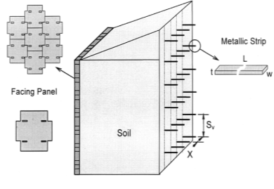
  • By inserting tensile reinforcing components (inclusions) within the soil, the strength of the soil is improved considerably specified the vertical face of the soil/ stimulant system is self-supporting,
  • The use of a facing system to forestall soil fiber between the reinforcing components permits steep slopes and vertical walls to be safely made. In some cases, the inclusions associate degree additionally stand up to bending or shear stresses providing further stability to the system
  • Reinforced soil may be a material shaped by the interaction of a granular soil with high adherence steel bolstered strips. The soil and reinforcement can resist the obligatory load thereon.
  • The reinforcement can carry the tensile stresses (soil is incapable of taking any tension). This idea was initiated by French engineer Gore Vidal in 1996 and now is widely employed in the construction of earth structures.
  • The recent trend is the use of synthetic fibers or Geosynthetics. In Asian country fiber, bamboo, palm leaf, coconut leaf, rice husk, grass, cotton haves a promising future. If used as construction material a soil is reinforced by mixing shortcutting of fiber in suitable proportion before it is placed at the site
  • Schematic diagram of a typical segmental reinforced soil wall with... |  Download Scientific Diagram

    Fig no 1 Schematic diagram of a reinforced earth wall


    REINFORCED EARTH WALL
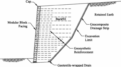
  • Geosynthetic bolstered Soil (GRS) could be a term accustomed to describe a specific group type of internally supported soil mass. Reinforcing components of geosynthetic (polymer) textiles square measure placed on prime of every raise of compacted soil because the mass is built to form the composite system.
  • Each soil raise is comparatively skinny (8 to sixteen inches or zero.2 to 0.4 m) and subjected to a high degree of compaction. Reinforcing steel adds tensile resistance that will increase the flexural, shear, and durability of the concrete composite.
  • Similarly, the addition of tensile elements (geosynthetics). In soil add here and shear strength to the soil composite.
  • In GRS, the closely-spaced reinforcing layers conjointly give confinement to the compacted layers of soil, and thru interaction with the soil grains, resist dilation of the soil, thereby limiting the formation of failure surfaces through the soil mass.
  • The principle of GRS has associated degree ancient technology, and samples of GRS victimization plant fiber mats as reinforcement still exist within the vertical walls of the ziggurats of ancient Mesopotamia and also the Great Wall of China.
  • The technology has been creating an advance within the geotechnical engineering community for the past twenty-five years, and GRS style methodology is getting used for bridge abutments, holding walls, arches, steepened slopes, rockfall barriers, and abutments for junk flow barriers.
  • Definition of Reinforced Earth | Chegg.com

    Fig no 2 Reinforced earth wall


    MECHANICALLY STABILISED EARTH WALL

  • The internally-supported GRS system is distinct from externally-supported soil holding systems normally employed in the railway setting
  • Retaining walls that square measure historically employed in the railway setting, together with tie-back walls that use H-pile and insulating material or sheet piles with whalers, yet as automatically stable Earth (MSE), gravity walls, and cantilever walls outwardly support the maintained soil mass and surcharge hundreds.
  • They have faith in a stiff facing component (e.g. gravity and cantilever walls) or a tied-back facing clement that resists the lateral pressures of the soil.
  • Although they'll see the same as GRS, MSE walls support a soil mass with a stiff facing that resists the lateral earth pressures of the soil and surcharges.
  • The stiff facing components square measure supported by steel strips or compound grids that anchor the stiff facing to the stable soil behind the active soil wedge with the GRS system, the facing will be versatile as a result of it's not meant to support the lateral earth pressures of the soil.
  • The GRS facing is needed to facilitate compaction of the soil, when that, it's solely needed to contain the soil between reinforcing layers (I e prevent raveling of the soil out of the face) and isn't a major load-bearing clement. the basic distinction in potential failure modes between GRS and MSE was studied
  •  


    FACTOR AFFECTING PERFORMANCE OF REINFORCED SOIL

    Reinforced soil could be stuff comprising of granular soil and reinforcement, therefore its behavior on the property of every material and also the bonding action between them to own additional interlocking friction

    Following factors can affect the performance of bolstered soil

  • The angle of internal friction of soil, that successively depends on the form and surface roughness of particle
  • Gradation of the soil mass
  • The density of soil.
  • Void magnitude relation of soil
  • Strength of reinforcement. 6. The surface roughness of reinforcement.
  • Length of reinforcement
  • Distribution of reinforcement
  • Advantages of reinforced Soil Structures

  • In several cases, soil materials on the market at the development sites will be used.
  • a pair of the bottom preparation isn't important - does not get to be flat for grade structure
  •  Wire mesh/geotextile material construction materials are lightweight, straightforward to move, and fast to construct.
  • the sole machinery needed could be a digger excavator (to place the soil fill) and a compactor (to compact the soil fill layers)
  • it's straightforward to make on curves (horizontal or vertical)
  • It is low cost compared to choices, like a standard concrete block.
  • Do not need old craftsmen with special skills for construction. & don't want rigid, unyielding foundation support as a result of such structures are tolerant to deformations
  • Are values effective
  • Are technically possible to heights in way over twenty-five m (80 ft).
  • Disadvantages

    The following general disadvantage is also associated with all soil bolstered structures.

  • need a comparatively giant house behind the wall or outward face to get enough wall dimension for internal and external stability
  •  MSE Walls need to choose granular fill. (At sites wherever there's a scarcity of granular soils, the value of mercantilism appropriate fill material could render the system uneconomical)
  • Requirements for bolstered soil slopes are usually less restrictive. the appropriate criterion is needed to deal with corrosion of steel reinforcing elements, deterioration of sure styles of exposed facing parts like geosynthetics by immoderate violet rays, and potential degradation of compound reinforcement within the ground

    Since design and construction apply of all bolstered systems are still evolving, specifications and catching practices haven't been standardized


    HISTORY OF SOIL REINFORCEMENT

  • In the past soil, reinforcement consisted of blending straw with mud, reinforcing with plain-woven reeds, and victimization branches and alternative stuff to boost strength and capability to support larger masses. soil reinforcement uses stronger and a lot of sturdy materials, however, employs several similar basic mechanisms that provided strength in these early applications.
  • Early versions of “modern” soil reinforcement were developed within the early Nineteen Sixties with Henri Vidal’s proprietary strengthened Earth for construction of independent holding walls.
  • These walls were made victimization galvanized steel strips with “ribs” to produce lateral resistance against earth pressures These sorts of wall (and equally slope) structures square measure generically stated as automatically stable earth (MSE).
  • Construction of earth walls with geosynthetic reinforcing materials was introduced within the Eighties (Federal main road Administration, 2011). Since that point, there has been an associate explosion of the utilization of geosynthetic reinforcement for soil structures yet as for several alternative geotechnical applications.
  •  

    Key takeaways

  • Generally, in the introduction, they give the idea about the properties of reinforced soil
  • There are 2 types of walls
  • Reinforced earth wall
  • Mechanically stabilized earth wall
  • Various factors are affecting the angle of internal friction, gradation, density, void, length, void magnitude, strength, etc.
  •  


    INTRODUCTION

  • Reinforced soil structures are shaped by compacted layers of soil fifty to a hundred and fifty cm thick during which reinforcing parts of acceptable length are interposed to boost overall resistance; the external face of the structure is protected by a facing which can carry with it shot and wire mesh, geogrid/geotextile sheets, standard facing blocks, cast-in-situ or prefab panels or similar
  •  The facing might incorporate biotechnical parts, usually for aesthetic functions solely.
  • Reinforced soil structures are typically applicable to things wherever the reinforcement parts and therefore the fill is placed because the wall is built.
  •  The thought of reinforcing the backfill behind holding walls was developed by H. writer in France within the middle 1960s).
  • These structures provide many blessings As highlighted for instance by Mitchell (1987), bolstered soil structures:
  • are coherent and versatile to tolerate comparatively massive displacements;
  • can use a good vary of backfill materials;
  • are simple to construct;
  • Are comparatively immune to loading; but their use in areas of high seismicity continues to be somewhat restricted owing to the dearth of definitive analysis on this issue; specifically, the affiliation between the reinforcing parts and therefore the facing parts is also crucial (Allen and Holtz, 1991).
  • can kind esthetically engaging holding walls and slopes owing to offered facing sorts
  • Are usually more cost-effective than typical holding structures, particularly for top steep slopes and high walls.
  •  


    GENERAL PRINCIPLES

  • In bolstered soil structures the reinforcing parts offer the structure with an element of strength. Because the height of the wall will increase, the overburden pressure will increase, and therefore the shear stresses at intervals the soil mass build-up. There is a bent for the face of the wall to displace outward that will increase because the height of the wall will increase.
  • The outward movement of the soil is resisted by the reinforcing parts that move into tension as resistance forces develop on them. Owing to the skinny nature of the reinforcing parts employed in this kind of structure, they'll solely offer tensile resistance.
  • The tensile forces acting within the reinforcements additionally contribute to the conventional stress acting on potential slip-surfaces at intervals of the bolstered soil mass, therefore increasing the resistance resisting force on them. Within the case of reinforcements consisting of grid mesh, with orthogonal strips running parallel to the face of the wall, there's additionally an element of resistance generated from their edge bearing against the soil infilling the gaps between the strips.
  • The maximum tensile forces within the parts occur at intervals of the bolstered soil mass instead of at the facing.
  • The locus of the purpose of most tensile force in every row of reinforcing parts separates the bolstered soil mass into 2 distinct zones, an associate degree “active” zone directly behind the facing and a “passive” zone. Contrary to soil-nailing structures, the position of the road of most tension may be moderately calculable in cases of bolstered soil structures thanks to their uniform pure mathematics and therefore the “known” characteristics of materials.
  • REINFORCING PARTS AND THEIR USES

    The reinforcing parts might consist of:

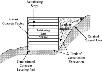
  • Metallic strips (Reinforced Earth);
  • Polymeric strips;
  • Geotextile sheets;
  • Geogrids;
  • Metallic grids.
  •  


    STRIP REINFORCING ELEMENTS

  • The mechanism of stress transfer between the reinforcement and therefore the soil is friction developed at the surface of the reinforcing strip (Mitchell 1987; patron saint and Holtz, 1989; patron saint et al., 1990).
  • Early experiments with fiberglass-reinforced polymers, chrome steel, and atomic number 13 strips weren't triple-crown thus all bolstered Earth walls are presently created exploitation galvanized steel strips (Schlosser, 1990).
  • As corrosion rates of metals in soil are tough to predict, additionally in presence of galvanized steel strips free-draining sand and gravel fills are fixed to scale back corrosion potential. Epoxy-coated steel strips are developed and will provide higher resistance to corrosion (Elias, 1990).
  • In theory, steel reinforcement might be designed with a killing thickness, however, this can be rarely economic considering the little initial thickness of the reinforcement parts, and therefore they have to be compelled to offer killing steel all spherical.
  • Since the middle Seventies, non-metallic strips are additionally developed (Holtz, 1978; Jones, 1978), consisting of continuous glass fibers embedded in a very protecting coating of epoxy or geosynthetic strips.
  • The reinforcement parts are connected to vertical prefab ferroconcrete panels or inclined steel mesh facing panels more and more assembled because the structure is built.
  • In a trial to boost the stiffness and pull out resistance of the reinforcement, bar-and-mesh systems or bar-mats shaped by cross-linking steel reinforcing bars were developed by Golden State Department of Transportation, Caltrans (Forsyth, 1978); laboratory tests showed that the bar-and-mesh reinforcement might manufacture considerably higher pull-out resistances compared to longitudinal bars solely (Chang et al., 1977).
  •  Evolving from the Caltrans project different bar mats systems have been developed and used (see for instance Anderson et al., 1987; Mitchell and patron saint, 1990). Most issues with bar mat systems are given by the corrosion of the steel bars.
  • a) Reinforced earth retaining wall with metallic strip, (b) Rankin... |  Download Scientific Diagram

    Fig no 3 Strip elements


    GEOTEXTILE SHEETS
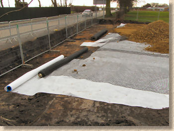
  • The use of geotextiles in bolstered soil structures followed shortly when the introduction of bolstered earth, (Bell and Steward, 1977; patron saint, 1988; Allen at al., 1992).
  • The mechanism of stress transfer between the reinforcement and therefore the soil is friction developed at the surface of the reinforcing sheets (Mitchell 1987; patron saint and Holtz, 1989; patron saint et al., 1990).
  • Large sort of nonwoven or plain-woven polyester and plastic geotextiles, with a good vary of mechanical properties obtainable (Christopher and Holtz, 1989; corner, 1990).
  • Coarse-grained soils starting from loose sands to gravel are usually used as fill.
  • The most common facings are shaped by wrapping the geotextiles around the exposed soil. Since the geotextiles are subjected to mischievousness, mechanical harm, and deterioration, the exposed materials should be coated with a shot or asphalt emulsion, standard facing parts, gabions, or soil and vegetation.
  • With the latter case, the facing usually includes further layers specifically designed to regulate erosion, consisting of variable combos of geogrids, geomatics, and/or perishable mats, to carry the soil in situ till the vegetation has taken hold.
  • The use of geosynthetics sheets rather than steel strips has been introduced and it's become increasingly} more in style chiefly on account of their lower value and bigger corrosion resistance. However, doubts persist on the sturdiness and longevity of geosynthetic materials owing to chemical and biological warfare (Elias, 1990; Allen, 1991; complete and Pang, 1991). The mechanical characteristics of geosynthetics additionally produce problems associated with their lower stiffness and their condition to vital creep
  • Landscape Fabrics | Pavingexpert

    Fig no 4 Geotextile sheet


    GEOGRIDS AND METALLIC GRIDS
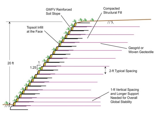
  • In grid reinforcement, chemical compound or argent parts are organized in rectangular grid form, with the long facet bound parallel to the direction of the movement between the reinforcement and {therefore the and also the} soil; therefore, the grid-soil interaction involves each friction performing on the long facet grid parts and passive bearing resistance on the short facet grid parts. Takes to the contribution of the passive bearing resistance grid reinforcements offer higher resistances to pull-out than flat strips; it ought to be thought of, however, that passive bearing resistance develops when comparatively massive displacements (5 to ten cm), see for instance Schlosser (1990).
  • Polymeric geogrids represent the foremost usually used component for soil reinforcement; they're created by plastic, synthetic resin or PVC coated polyester. Since the Seventies, advances within the formulation of polymers semiconductor diode to vital improvement in their strength and stiffness and their use for many applications, as well as repair of slope failures (O’Rourke and Jones, 1990; Murray and Irwin, 1981; Murray, 1982; Jones, 1985; Forsyth 1984; Mitchell and patron saint, 1990). Like the geotextile sheets, chemical compound geogrids are at risk of environmental deterioration, massive deformations, and creep.
  • Coarse-grained soils starting from loose sands to gravel are usually used as fill.
  • Requirements and details of facings are just like those delineated higher than for structures created with geotextile sheets.
  • Whatever the bolstered soil structures, provision of voidance behind the facing and therefore the bolstered soil mass is very important, to maximize effective stresses at intervals the fill and offered shear strength at the soil reinforcement interfaces. Allowance for voidance from the facing ought to even be created.
  • For a lot of comprehensive description and discussion on bolstered soil structures reference may be created, for instance, to Lee et al. (1973), Jones (1985), Mitchell (1987), patron saint et al. (1990), Mitchell and patron saint (1990), O’Rourke and Jones (1990), Dot recommendation note HA/68/94 (1994), baccalaureate 8006 (1995), Love and Milligan (1995), Jewell (1996), Jones (1996), Berg et al. (2009).
  • GWFV walls and slopes – Geosynthetics Magazine

    Fig no 5 Geogrid


    Key takeaways

    Use of soil reinforcement in different reinforcing parts
  • Metallic strips (Reinforced Earth);
  • Polymeric strips;
  • Geotextile sheets;
  • Geo grids;
  • Metallic grids.
  •  


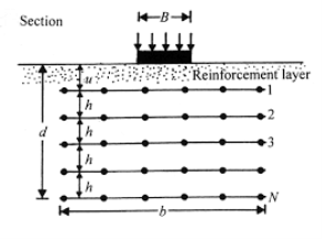
  • This analysis study aims at investigating the potential edges of bolstered soil foundations to boost the bearing capability and cut back the settlement of shallow foundations on soils.
  • To implement this objective, a complete of 117 tests, as well as thirty-eight laboratory model tests on loose clay hill soil, fifty-one laboratory model tests on the sand, twenty-two laboratory model tests on Bluegrass State crushed stone, and half dozen giant-scale field tests on loose clay hill soil were performed at the American state Transportation center to check the behavior of bolstered soil foundations.
  • The influences of various variables and parameters tributary to the improved performance of bolstered soil foundation were examined in these tests. Additionally, an instrumentation program with pressure cells and strain gauges was designed to research the strain distribution in soil mass with and while not reinforcement and therefore the strain distribution on the reinforcement.
  • Numerical analysis of shallow foundations on geogrid reinforced soil

    Fig no 6 Shallow foundation


  • The take a look at results showed that the inclusion of reinforcement will considerably improve the soil’s bearing capability and cut back the footing settlement.
  • The geogrids with higher tensile modulus performed higher than geogrids with lower tensile modulus.
  •  The strain developed on the reinforcement is directly associated with the settlement, and so higher tension would be developed for geogrid with higher modulus underneath constant footing settlement.
  •  The take a look at results conjointly showed that the inclusion of reinforcement can spread the applied load to a wider space, therefore minimizing stress concentration and achieving additional uniform stress distribution.
  • The distribution of stresses below the bolstered zone can end in reducing the consolidation settlement of the underlying weak clayey soil, which is directly associated with the iatrogenic stress.
  •  Insignificant strain measured within the geogrid on the far side its effective length of four.0~6.0B indicated that the geogrid on the far side of this length provides a negligible additional reinforcement impact. To boot, finite component analyses were conducted to assess the advantages of reinforcing hill soil of low to medium physical property and crushed stone with geogrids below a strip footing from the angle of the last word bearing capability and footing settlement. Supported the numerical study, many geogrid-reinforcement style parameters were investigated.
  •  


    Designing for Condition

    (a): Pore water Pressures Generated among the bolstered Fill
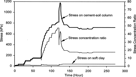
  • There is sensible proof the geosynthetics with adequate transmission and vertical spacing on the order each of each} compaction raise or every different compaction raise (e.g. two hundred to three hundred mm) will dissipate excess pore pressure on the interface of the semipermeable inclusions throughout construction. However, excess pore water pressures could develop among the soil mass between
  • Geosynthetic layers throughout construction, particularly if extremely plastic soil area unit used as backfill material. Considering the issue in accurately evaluating the distribution of pore water pressures generated throughout construction a two-phase analysis is planned. These analyses, summarized in Table one, area unit as follows:
  • Responses of Excess Pore Water Pressure in Soft Marine Clay around a  Soil–Cement Column | International Journal of Geomechanics | Vol 7, No 3

    Fig no 7 Pores water pressure


    1.  Total stress analysis ignoring reinforcement lateral voidance. This analysis neglects the dissipation of pore water pressures through the semipermeable inclusions to supply a conservative estimate of the steadiness of the structure at the top of the construction. Considering the short condition and also the conservative assumptions during this analysis, an element of safety of one.1 is suggested. This analysis determines minimum reinforcement necessities that will preclude collapse throughout the construction of the structure. That is, it provides reinforcement necessities for a short scenario within which stability is provided largely by the tensile forces within the reinforcements with solely a minor contribution by the undrained shear length of the backfill. The undrained soil shear strength of the backfill for this analysis ought to be supported by loose undrained (UU) triaxial tests. The specimens ought to be ready at representative field densities and wetness placement conditions, and tested at these placement conditions below project-specific confining pressures. Though the authors contemplate testing below unsaturated conditions as AN adequate approach, testing below absolutely saturated conditions represents an extra degree of ideology that the designer could contemplate on a project-specific basis.

    2. Effective stress analysis accounting for full lateral voidance by the reinforcement. Full voidance of the bolstered fill is assumed for the long conditions. This analysis provides a practical analysis of the long stability of the structure, as a result of the dissipation of pore water pressures generated throughout construction ought to have occurred through the semipermeable inclusions. This analysis determines the minimum reinforcement necessities which will offer adequate stability below long conditions following the dissipation of pore water pressures generated throughout the construction of the structure. it'sstressed that the transmission of the reinforcements ought to be designated so the generation of pore water pressures is prevented at the soil-reinforcement interface. Typically, the soil shear strength ought to be supported by consolidated undrained (CIU) triaxial tests performed on saturated samples with pore pressure measurements or consolidated drained (CD) triaxial tests. The long-run style issue of safety usually needed for reinforcement of granular fills (e.g. 1.3 to 1.5) ought to be employed in this analysis.

  • The reinforcement strength eventually designated is that the higher worth obtained from analyses (i) and (ii). Moreover, the minimum reinforcement length designated for style ought to be the larger worth outlined from the 2 analyses. Note that the analyses represented higher than addressing internal stability. However, the specified length of the reinforcement should additionally contemplate the external stability of the structure. External stability ought to contemplate the undrained soil shear strength for the fill maintained behind the bolstered zone if it's to be made with similar marginal fill. For cut slopes, acceptable pore water pressure assumptions ought to be created for field conditions.
  • It ought to be noted that an efficient stress analysis might are planned to judge the short stability of the structure, rather than the whole stress Analysis an efficient stress analysis would additionally accurately account for the in-plane voidance capability of the geosynthetic and also the corresponding increase in soil strength. Also, an efficient stress analysis would facilitate analysis of the backfill placement rate that might cause an acceptable stability issue of safety throughout construction. The issue during this approach is that the correct determination of the pore water pressures among the fill. They may be calculable from direct measurements in field trials (e.g. check pads) or sealed laboratory specimens (one raise thick with a geosynthetic on the lowest and high connected to empty lines) subjected to fret levels anticipated throughout construction. Instead, pore pressures may well be on paper calculable supported by one-dimensional consolidation theory and also the assumption of full saturation of the backfill material throughout construction. AN analysis of this approach is on the far side of the scope of this paper.
  •  Designing for Condition

    (b): Wetting Front Advancing into the bolstered Fill

    As loss of strength could occur attributable to a wetting front advancing into the bolstered fill geosynthetic transmission necessities ought to be established to avoid the advancement of wetting front for expected conditions. A two-phase analysis is additionally planned during this case. These analyses, summarized in Table one, area unit as follows:

    1) Total stress analysis ignoring the result of lateral voidance in preventing the advancement of a wetting front. This analysis is performed exploitation shear strength properties of the bolstered soil mass outlined exploitation saturated specimens. The results of this analysis offer an estimate of the steadiness of the structure below an advancing wetting front. This analysis is conservative as a result of the backfill is assumed saturated, which mustn't occur in actual follow as a result of the wetting front is intercepted by the semipermeable reinforcements. Consequently, an element of safety of one.1 is suggested during this case. Water pressure which will develop as water fills surface cracks (induced by desiccation, freeze/thaw, or slope movements) ought to be accounted for exploitation boundary water pressures within the analysis.

    2)  Total stress analysis accounting for the result of lateral voidance in preventing the advancement of a wetting front. The whole shear strength is outlined from unsaturated specimens ready at the best wetness anticipated within the fill. Note that the whole shear strength outlined from unsaturated specimens ought to be more than the effective shear strength of the fill. Complete stress analysis is taken into account during this case, rather than an efficient stress analysis, to account for the helpful result of the negative pore-water pressures within the unsaturated bolstered fill. The shear strength of the bolstered fill higher than the highest bolstered layer (which could become saturated) ought to be obtained from saturated specimens. This analysis provides a practical analysis of the steadiness of the structure as a result of it accounts for the lateral voidance of the geosynthetic reinforcements.

    Designing for Condition

     (c): Seepage Configuration Established among the bolstered Fill

  • Post-construction pore water pressures may well be generated by snooze configuration developing among the backfill material. Such a flow configuration could develop seasonally throughout rainy periods or spring although.
  •  A snooze configuration may additionally develop thanks to water level fluctuations in structures subjected to flooding or made adjacent to or among bodies of water. Finally, ooze forces may well be evoked by surface water infiltration.
  • The ooze configuration will be determined for AN unreinforced mound exploitation flow nets for ooze analysis. Transmission necessities within the geosynthetic inclusions area unit specifiedreinforcement ought to convey absolutely the flow amount it intercepts (as calculable from a flow internet outlined in an unreinforced slope).
  •  A two-phase analysis is additionally planned during this case. These analyses, summarized in Table one, area unit as follows:
  • 1. Total stress analysis ignoring reinforcement lateral voidance. This analysis considers ooze forces outlined from a flow configuration that might develop in an unreinforced slope. The results of this analysis offer a conservative estimate of the steadiness of the structure throughout a seasonal speedy configuration of ooze flow among the fill. The ideology of this analysis is as a result of (1) the backfill is assumed as absolutely saturated, which does not occur in actual follow, and (2) the ooze configuration doesn't account for the lateral voidance provided by the reinforcements. Therefore, a comparatively low issue of safety of one.1 is suggested during this case (note that ooze forces area unit thought of within the analysis).

    2. Effective stress analysis accounting for full reinforcement lateral voidance. Full voidance of the bolstered fill is assumed for the everyday condition of the structure. This analysis provides a practical analysis of the long stability of the structure as a result of it accounts for the lateral voidance of the geosynthetic reinforcements. No ooze forces area unit thought of to develop among the bolstered fill if the reinforcements offer adequate internal voidance.

  • As indicated, the transmission and range, and site of layers ought to be designated so the geosynthetics have in-plane voidance capability to accommodate the complete ooze flowing into the bolstered fill. Otherwise, external groundwater and surface water management systems (e.g. base and back drains and surface collectors) should be incorporated into the planning.
  • The soil shear strength within the 2 analyses (total and effective stresses) ought to be determined exploitation saturated samples to account for the potential loss of shear strength below soaked conditions.
  •  

    Key takeaways

    Design consideration depending on various conditions

  • Pores water pressure generated among the bolstered fill
  • Wetting front advancing into the bolstered fill
  • Seepage configuration established among the bolstered fill

  • IDEALIZED SOIL RESPONSE MODELS FOR THE ANALYSIS OF SOIL-FOUNDATION INTERACTION
  • A cross-sectional of soil prime, revealing horizons a soil horizons a layer typically parallel to the soilsurface, whose physical characteristics dissent from the layers on top of and at a lower place every soil sort sometimes has 3 or four horizons.
  • Horizons square measure outlined in most cases by obvious physical options, mainly color, and texture. These are also each in absolute terms. (Particle sizes distribution for texture, for instance) and in terms relative to the encircling material (i.e., "coarser" or "sandier" than the horizons on top of and below).
  • The differentiation of the regolith into distinct horizons is the result of influences, like air,water, radiation, and material, originating at the soil-atmosphere interface. Since the weathering of the regolith happens 1st at the surface and works its means down, the upmost layers are modified the foremost, whereas the deepest layers square measure most like the initial regolith (i.e., parent material).
  • The analysis of the response of soil media to external hundreds constitutes an element of elementary importance to the analysis of soil-foundation interaction issues.
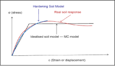
  • Evaluation of Foundation Settlement under Various Added Loads in Different  Locations of Iraq Using Finite Element

    Fig no 8 Idealized soil


  • Such Associate in the Nursing analysis will be created solely from a apprehend shelf of the whole stress-strain characteristics of the soil.
  • The strain relation square measure the mathematical description of the mechanical professional practice of the soil – its organic equations. An entire stress-strain relationship for soil can furnish a minimum of in theory, the stresses and strains in a very soil medium at any specific time below any given loading condition.
  • Takes to the range of soils and soil conditions which will be encountered in engineering follow, it looks unlikely that generalized stress-strain relations are developed to satisfy the necessities of each style of soil behavior particularly regarding the analysis of the interaction between the soil and therefore the foundation.
  • This limitation is clearly illustrated by the very fact that within the history of the development of soil mechanics, elastic, consolidation, creep and failure processes in soils are analyzed by separate theories of fabric behavior.
  • A substantial proportion of the analysis activity in geotechnical engineering has thus been dedicated to the event of stress-strain-time relationships for soils that exhibit non-linear and irreversible processes
  •  Though some progress has been created within the application of those generalized organic relationships to the examination of elementary phenomena encountered below check conditions, their pertinence to the analytical or numerical answer of boundary price issues in soil-foundation interaction presents formidable difficulties.
  • The inherent quality within the behavior of real soils has junction rectifier to the event of the many idealized models of soil behavior particularly for the analysis of soil-foundation interaction issues.
  • The classical theories of the physical property and physical property square measure 2 such idealizations are usually utilized within the analysis of issues in soil mechanics. The idealized foundation model or, for that matter, the generalized stress-strain relations for soils, aren't actual descriptions of even the gross physical properties of real soil media.
  • the simplest which will be aforesaid of any such model of soil response or material behavior is that it provides a helpful description of bound options
  •  


    Soil-structure interaction interdisciplinary field that involves structural and geotechnical engineering. Within the standard non-interaction analysis of the building frame,the structural designer assumed that columns are resting on unyielding support.

  • Similarly, in foundation style, foundation settlements are calculated while not considering the influence of the structural stiffness. Although, interaction result is unnoticed to modify the mathematical model however neglecting the interaction between soils and structures might lead to a style that's either unnecessarily expensive or unsafe.
  • An additional rational answer of soil-structure interaction downside will be achieved with machine validity and accuracy by applicable analysis.
  • The current study makes a shot to review the potential different solutions projected by numerous researchers to judge the result of soil-structure interaction from time to time.
  • 1. Introduction

  • Several studies are created on the result of soil-structure interaction issues to get additional realistic analysis. They need to quantify the result of interaction behavior and established that there's the distribution of forces within the structure and soil mass. Hence, structures and their supporting soils ought to be thought of as one compatible unit.
  •  The interaction effects are found quite important, notably for the structures resting on extremely compressible soils. The flexibleness of soil mass causes the differential settlement and rotation of footings beneath the appliance of the load. The relative stiffness of the structure, foundation, and soil influence the interaction behavior of the structure foundation-soil system
  • 2. Linear soil-structure interaction beneath static loading
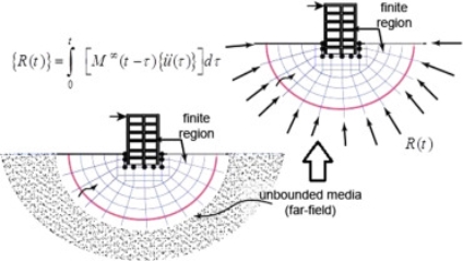
  • The interaction behavior of plane frames with AN elastic foundation of the Winkler's sort, having traditional and shear modulus of sub-grade reactions is studied by
  • An exactstiffness matrix for a beam part on an elastic foundation having solely a traditional modulus of subgrade reaction was changed to incorporate the shear modulus of the sub-grade reaction of the inspiration yet because of the axial force within the beam. The results indicated that bending moments can be significantly affected in line with the sort of frame and loading.
  • The potency of the coupled finite-infinite parts formulation with relation to machine effort, information preparation, and also the way field illustration of the boundless domain is investigated
  •  Given a simplified procedure for the analysis of soil-structure interaction behavior of two-dimensional skeletal steel or concrete frame structures resting on isolated footings that are supported by differing types of soil. Most programs are made from 2 major modules; one for soil settlement calculations and another for the analysis of the structure. They evaluated the result of interaction on the expected settlements, footing hundreds, and internal bending moments of the structural members
  •  Performed an analysis on an idealized model consisting of a multi-story 3-D frame structure with a grid foundation. The grid foundation is assumed to rest on springs that idealize the soil behavior.
  • The result of soil-structure interaction on an area frame resting on a pile cluster embedded within the cohesive soil (clay) with a versatile cap is examined by task et al.
  •  

    2-D soil-structure interaction in time domain by the SBFEM and two non-linear  soil models - ScienceDirect

    Fig no 9 Linear soil structure


  • They evaluated the results of pile spacing, pile configuration, and pile diameter of the pile cluster on the response of the structure. The result of soil-structure interaction is found to be quite important. The result of contact between strap beam and bearing stratum is studied by Guzman
  • The results indicate that once a strap footing is employed as a part of a foundation system, details that leave pressure to be mitigated from the strap beam is important on construction documents. Without it, a substantial unforeseen load path may well be created that will lead to the failure of the strap beam followed by an overstate of the soil beneath the eccentric footing. The interaction and non-interaction analyses for the area frame-raft foundation-soil system exploitation analysis  finite part code is compared
  •  The soil was treated as an isotropous, homogenized, and elastic 0.5 area medium. an in-depth constant quantity study was conducted by varied the soil and raft stiffness for a relentless building stiffness
  • The interaction analysis showed fewer total and differential settlements than the non-interaction analysis and the relative stiffness of soil plays a major role in the performance of the raft. The strain and settlement distribution of a tank foundation by exploitation of the finite part analysis computer code (ANSYS) is studied
  • The results indicate that the finite part methodology will simulate the settlement of a tank foundation faithfully. The operation of finite part analysis is convenient and desires less instrumentation than the standard methodology of the experiment. The result of this methodology is a twin of that of the standard methodology.
  • They conclude that it's a sensible and valuable methodology for analyzing and learning the strain and settlement distribution of a tank foundation, which might even be accustomed to study different foundation sorts. The results of horizontal stresses and horizontal displacements in the loaded foundation are studied
  •  The numerical experiments are performed on 3-dimensional mathematical models. The results of unconnected analysis i.e., complete slip/frictionless interface between foundation and soil, and also the coupled analysis i.e., complete welding/bonding of joints between foundation and soil parts were compared with the results of the non-interactive analysis.
  • They ended that the response of the structure will amendment in soil-structure-interaction analysis in comparison to non-interactive analysis however member finish actions for beams and columns are nearly the same in the coupled and unconnected analysis.
  • 3. Nonlinear soil-structure interaction beneath static loading

  • A simplified, sensible nonlinear stress-strain relationship for soils that is convenient to be used with the finite part methodology of research is delineated by professional dancer and Chang Jiang. The Mohr-Coulomb strength parameters, cohesion, and angle of internal friction are concerned during this relationship.
  • A finite part procedure for the overall three-dimensional soil-structure downside interaction involving nonlinearities caused by the material behavior, geometrical changes, and interface behavior is given by Desai et al.  The formulation was supported the updated approach with applicable provision for constitutional laws.
  • The influence of little strain non-linearity of low physical property clay compared with linear elastic behavior. They found that non-linear behavior leads to the concentration of strain and deformation towards the loading boundaries.
  • PDF] Non-Linear Seismic Soil-Structure Interaction Analysis Based on the  Substructure Method in the Time Domain | Semantic Scholar

    Fig no 10 Non liner soil structure


  • The soil-structure interaction result in framed structures with correct physical modeling of the structure foundation and also the soil mass is evaluated
  • The hyperbolic stress-strain model has been accustomed contemplate the soil non-dimensionality. The interactive behavior of a 5 story 2 bay plane frame has been studied thoroughly and also the results area unit compared with those obtained from a traditional and linear interactive analysis.
  • Bestowed a replacement approach for the physical and material modeling of an area frame-raft-soil system. The beams and columns of the structure are disturbed by a changed Timoshenko beam bending part with six degrees of freedom per node and structural slabs and raft area unit disturbed by a changed plate bending part with 5 degrees of freedom per node.
  • The soil media is delineated by the coupled finite-infinite parts with 3 degrees of freedom per node. Organic modeling involves the utilization of the hyperbolic model to account for the soil nonlinearity. They compared the behavior of the house frame-raft-soil system below the linear and nonlinear interaction.
  • The result of the differential settlement on style force quantities for frame members of building frames with isolated footings is studied by Roy
  • They bestowed numerous representative case studies for frames resting on sandy soil and clayey soil by idealizing the soil medium below the footing as linear and nonlinear severally.
  •  Used the Ritz methodology to resolve the bending downside of a transversally loaded rectangular thick raft with free edges, resting on Associate in nursing elastic half-space.
  • The doable various models for the structure-foundation-soil interaction system out there within the literature area unit studied by Roy
  • Stress was given on the physical modeling of the soil media. For the sensible purpose, it's found that the Winkler hypothesis, despite its limitations, yields cheap performance and it's straightforward to exercise.
  • Finite part modeling with the nonlinear idealization of soil media was found to be the foremost powerful and versatile tool for determining soil structure interaction downside which may incorporate the result of fabric nonlinearity, nonhomogeneity, and property of the supporting soil media. To perform such Associate in nursing analysis, the progressive reiterative technique was found to be the foremost appropriate and general one.
  • Bestowed the process methodology adopted for nonlinear soil-structure interaction analysis of in the filled frame-foundation-soil system. The limitless domain of the soil mass has been disturbed with coupled finite-infinite parts to realize the process economy. The nonlinear behavior of the soil mass was modeled victimization hyperbolic model. The incremental-iterative nonlinear resolution rule was adopted for winding up the nonlinear elastic interaction analysis. The interaction analysis showed that the nonlinearity of soil mass plays a crucial role in the distribution of forces within the structure.
  •  Compared 2 ways in which of modeling shallow foundation stiffness. One methodology assumes that the soil at a lower place the inspiration will be perfect as Associate in Nursing elastic time and also the alternative that the soil will be delineated as a bed of freelance springs.
  • They over that the move stiffness of a bed of springs is a smaller amount than that of a nonstop elastic material and nonlinear soil behavior features a larger result on the move stiffness than vertical stiffness.
  • The influence of column spacing on the behavior of an area frame-raft-soil system below static load is studied
  • The analyses were administrated for linear and non-linear conditions, during which soil was treated as undiversified and isotropous time. The settlement was larger within the non-linear analysis and also the settlements were higher for higher column spacing. Contact pressure distribution was a lot uniform within the non-linear case and its magnitude was but that of linear soil, significantly within the finish panels of the raft.
  • 4. Elastic-plastic soil structure interaction below static loading
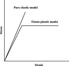
  • Desai and lighter evaluated hybrid finite part procedure for nonlinear elastic and elastic-plastic soil-structure interaction analysis together with simulation of construction sequences.
  • An elasto-plastic finite element model for polyethylene wear in total hip  arthroplasty - ScienceDirect

    Fig no 11 Elastic-plastic soil structure


  • The elastic-perfectly plastic behavior of the compressible soil is studied Interaction analysis is performed on the plane frame-combined footing-soil system.
  • Comparison of the interactive behavior has additionally been created with the non-interactive behavior and additionally with the behavior of the system once the sub-soil is taken into account as behaving in an exceedingly linear elastic and non-linear elastic manner.
  • A hyperbolic illustration of the stress-strain behavior of the soil mass has been used for the non-linear analysis. The elastic-plastic analysis has been administrated victimization six different yield criteria for soils.
  • 5. viscosity-elastic/plastic soil-structure

  • interaction below static loading A three-dimensional viscosity-elastic finite part formulation for learning the interactive behavior of house frames, taking under consideration the stress/strain-time response of supporting soil medium is presents
  •  The methodology for evaluating time-dependent viscosity elastic constants for the soil mass is given. The results area unit compared with the structural behavior therewith once the interaction is neglected.
  • The principles of elastic/viscosity plastic finite part analysis area unit bestowed by Abdullah  malleability models like Von and Mohr-Coulomb models with associated and non-associated flow rules were incorporated within the viscosity plastic rule
  • the last word bearing capability of a rigid surface footing resting on weightless clayey soil expected by model agrees okay therewith obtained by actual resolution.
  • 6. Soil-structure interaction below dynamic loading
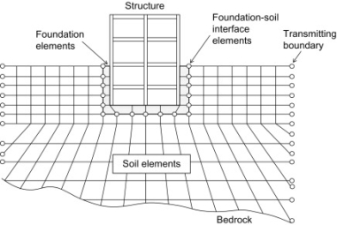
  • The result of progressive loading throughout the development of the frame on the frame foundation-soil interaction is examined by Brown and Yu
  • The interaction analysis results of plane and house frames show that the effective stiffness for interaction functions, of a building that's loaded increasingly throughout construction, is regarding 0.5 the stiffness of the finished building.
  • A perfect 2-dimensional plane strain seismic soil-structure interaction analysis supported a substructure methodology is bestowed by research the interaction result non-interaction analysis and linear and nonlinear analyses were performed. Computations were created by taking a totally different peak acceleration and shear wave rate. The soil malleability was a failure criterion.
  • Three-dimensional finite part analysis in the time domain on dynamic soil-pile-structure interaction of a tall building is administrated by Lu et al. The viscous boundary of soil is enforced in the all-purpose finite part program (ANSYS) utilized in the analysis. The influences of parameters, like soil property, excitation, buried depth, and also the rigidity of the structure, on dynamic characteristics, seismic response, and interaction result of soil-structure action system area unit mentioned.
  • Soil Structure Interactions - an overview | ScienceDirect Topics

    Fig no 12 Soil structure interaction below dynamic loading


  • The result of soil flexibility aboard shear and unconnected lateral natural amount quantitative relation is examined by Bhattacharya et al. The results of the study conclude that the result of soil-structure interaction might cause a sizeable increase in seismic base shear of low-rise building frames, significantly those with isolated footings. The result of soil-structure interaction and fluid-structure interaction on elevated tank below seismic loading is studied
  • The necessary contribution of infill walls within the resistance of earthquake hundreds in conjunction with a presentation of the behavior modes of the infill and also the bounding frame is documented
  • Recommendations area unit created for the in-plane material properties, failure modes, strength, and stiffness furthermore as deformation characteristics of frames.
  • The interaction result of frame, isolated footing, and soil media below seismic loading is studied in numerous analyses area unit performed on the frame-footing-soil system by considering a plane frame, infill frame, undiversified soil, and bedded soil mass. The frame is taken into account to act in a linear elastic manner whereas the soil mass act in a nonlinear elastic manner.
  •  They over that the shear forces and bending moments in structure get considerably altered because of differential settlements of the soil mass.
  •  

    Key takeaways

    They include

  • Introduction
  • Linear soil structure interaction beneath static loading
  • Non-linear soil structure interaction beneath static loading
  • Elastic-plastic soil structure interaction below static loading
  • Viscosity elastic /plastic soil structure
  • Soil structure interaction below dynamic loading
  •  


    References:

    1. C venkataramaiah: geotechnical engineering

    2. Taylor D W: Fundamental of soil mechanics,Mumbai

    3. Arora KR: soil mechanics and foundation engg, Delhi


    Index
    Notes
    Highlighted
    Underlined
    :
    Browse by Topics
    :
    Notes
    Highlighted
    Underlined