Unit-1
Introduction to Various Design Philosophies
INTRODUCTION
HISTORIC DEVELOPMENT
Advances and Future Tends In R.C.C.
INTRODUCTION TO VARIOUS DESIGN PHILOSOPIES OF R.C. STRUTURES
Concrete is strong in compression but week in tension
Steel is reinforced suitable at the place where concrete is weak in tension such combination of steel and concrete
The purpose of R.C structure is increase strength of concrete section and to reduce the size of structural member
Various design philosophies of R.C structure are
Reinforced concrete is used to construct various structures

Fig no 1
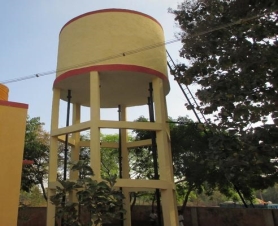

Fig no 2 Flyover
Following are the various methods for RCC structure
1. Working stress methodology (WSM).
2. Ultimate load methodology (ULM).
3 Limit state methodology (LSM).
Limitations of WSM strategies over LSM
Advantages of reinforced concrete
1. Strength
It has excellent Tensile likewise as compressive strength a pair of malleability
2. Ductility
Ductility of structures is increase thanks to steel reinforcement
3. Durability
R.C. structures are more durable
4. Mouldability
The flexibility of reinforcement and therefore the liquidness of concrete makes the R.C. member to be mould in any form thus it's appropriate for architectural demand.
5. Porosity
RC members are impermeable to wet
6. Fireplace resistance
R.C. structures are additional fireplace resistance than alternative materialssuch as steel and wood
7. Economy
R.C.C is cheaper than steel and pre stressed concrete
Disadvantages of R.C.C
RCC has followed disadvantages
1. Weight of R.C. structures are measure over different materials
2. Significant formwork is needed for R.C. members
3. RC structures take a lot of times to realize its full strength
Reinforced concrete building elements
1. Slab
2. Beam
3. Column
4. Footing
Design of every parts is depends on load on structure and structure action of member subjected to the current load.
Load transfer mechanism la RC building is load from block is transferred to the supporting beams, and from beam lo column and from column to footing ultimately footing transfer the masses to soil strata.
1. Slabs
Slab is that the 2-dimensional component that is plate component. As a result of the depth of block is thus smaller than its length in x and y direction. It is a flexural member subject to transverse load.
2. Beams
Beam is he one dimensional component that is subjected to transverse beam carries load from slabs, from masonry walls and then self-weights Beams is also supported on another beam old is also on supported on column Failure of beam are native failure, which may lead to failure of that floor
3. Columns
Columns square measure typically the vertical member subjected to axial or eccentric hundreds. The load carries by column is comes from beans and from higher columns if any. The column is incredibly necessary support because failure of column lends to collapse of whole structure.
4. Footing
Footing is the strong base to the structures. It helps to transmit the loads from structure uniformly to the large are beneath
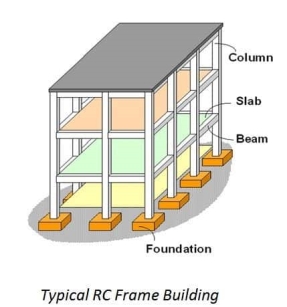
Fig no 4
Working Stress Method (WSM)
Ultimate Load Method
Load factor= Collapse load / working load
Limit State methods
Permissible Stresses for Materials within the WSM
Permissible stresses for different type of grades of concrete
Grade of concrete | Permissible stress in compression | Permissible stress in compression | Permissible stress in bonds |
| Bending | Direct |
|
M10 | 3 | 2.5 | - |
M15 | 5 | 4 | 0.6 |
M20 | 7 | 5 | 0.8 |
M25 | 8.5 | 6 | 0.9 |
M30 | 10 | 8 | 1 |
M35 | 11.5 | 9 | 1.1 |
M40 | 13 | 10 | 1.2 |
M45 | 14.5 | 11 | 1.3 |
M50 | 16 | 12 | 1.4 |
Permissible stresses in steel in tension
Reinforcement | Permissible | Stress | In N/mm2 |
| Mild steel bar graph
| High yield strength | Deformed bar |
|
| Fe 415 | Fe500 |
r/f up to including 20 mm | 140 | 230 | 275 |
r/f over 20 mm | 130 | - | - |
Assumptions created in working stress method
 MODULAR RATIO
The ratio between modulus of elasticity of steel to concrete is called as modular ratio.
M = Es/Ec
M= 280/3 
Grade of concrete | Modular ratio |
M15 | M=280/3*5=28.66 |
M20 | M=280/3*7=13.33 |
M25 | M=280/3*8.5=10.98 |
M30 | M=280/3*10=9.33 |
BEAMS
Beams are the flexible members are classified into 2 types
Based on geometry
2. Flanged beam
3. Based on mode of failure
TYPE OF REACTANGULAR BEAM
Singly reinforcement beams
The beams section in which reinforcements provided to resist only tension is called as singly reinforcement section.
In such beams steel provided only one side of the section
Doubly reinforcement beams
The beam section in which reinforcements in which reinforcements is provided to resist tension and compression is called as doubly reinforcements section.
In such beam steel is provided on both side of the neutral axis
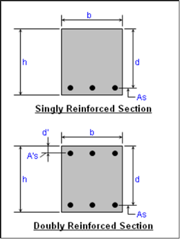
Fig no 5 Singly and doubly reinforced beams
Balanced, under –reinforcement and over reinforcement section for WSM
.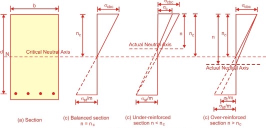
Fig no 6 Types of reinforced section
Balanced section
 c b c/
  s t/m = X c / d – X c
Under reinforcement section
(b x) x/2 = m A s t (d – x)
X < X c
Over reinforced section
X > X c
Comparison between various sections
S R NO | Description | Balanced Section | Under reinforcement section | Over reinforcement section |
1 | Steel | Steel provided as per requirements | Steel provide less than requirements | Steel provided more than requirements |
2 | Neutral axis | X =XC | X<XC | X>XC |
3 | Actual stress of concrete | ( | ( | ( |
4 | Actual stress in steel | ( | ( | ( |
5 | Moment of resistance | MR =T*Z =C*Z | MR = T*Z | MR =C*Z |
6 | Economic | economical | More economical | costlier |
7 | safety | More safe | Fails in tension | Fails in compression |
Need of under reinforced section in LSM design
BASICTERMONOLOGY
EFFECTIVE DEPTH
Effective depth of section is the distance between the center of the area of tension reinforcement and maximum compression fiber
d = overall depth –effective cover
d =D - /2 – clear cover
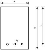
Fig no 7 Effective depth
CLEAR COVER
The minimum distance between the surface of concrete to the outside of the reinforcements is called clear cover.
D=d+  /2 +cover
It is provided to protect reinforcements from whether and fire so that if does not corrode or melts
To produce the grip of concrete to steel
To develop the sufficient bond strength along the surface area of the steel bar
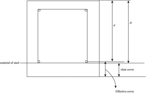
Fig no 8 Effective depth
EFFECTIVE COVER
It is distance between extreme compression fiber of centre of tensile reinforcements
EFFECTIVE COVER =OVERALL DEPTH –EFFETIVE DEPTH
Nominal cover is the design depth of concrete cover to all the steel reinforcements including links
It shall not be less than the diameter of bar
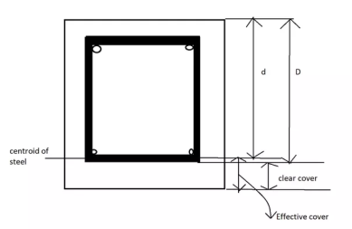
Fig no 9 Effective cover
Minimum cover for various structural elements as per clause 26.4
Structural elements | Minimum cover |
Beam | 20 |
Slab | 15 |
Column | 40 |
Column footing | 50 |
Nominal cover to meet durability requirements as per clause 26.4.2 and table 16 I.S 456:2000
Exposure condition | Minimum cover not less than |
Mild | 20 |
Moderate | 30 |
Serve | 45 |
Very serve | 50 |
Extreme | 75 |
Neutral Axis in the Section
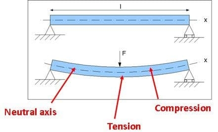
Fig no 10 Neutral axis
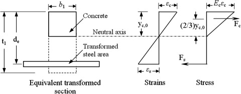
Fig no 11 Transformed section
Es =E c
 s / Es =
 e/E e
e/E e
 s =Es/E e *
 e =m
e =m e
e
 e =
e = s/m
s/m
A equivalent =A+ (m-1) A s t
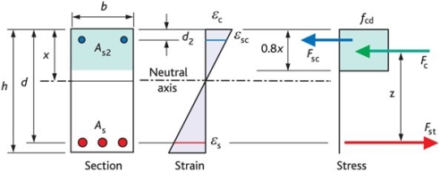
Fig no 12 Position of N A when stress induced in section
.
E c =maximum strain in concrete
E s = maximum strain in steel
F c d =compressive stress in concrete in bending
F st = stress in steel in tension
E c = c b c /E c
And E s =  s t /E s
Stress strain diagram is linear, hence the strain in concrete and steel are proportional to N.A
E c/E s=x/ (d-x)
( c b c/E c)/ (
 s t /E s) =x/ (d-x)
( c b c /
 s t)*(E s /E c) = x/ (d-x)
Where m, E s /E c =m
 c b c / s
 t * m =x/ (d-x)
X = [1/(1+( s t /(m *
  c b c))]* d
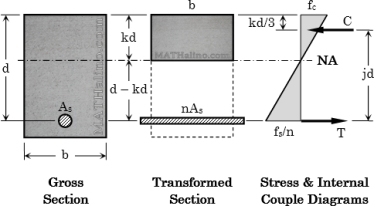
Fig no 13 Position of N A when section is known
(Moment of area in compression about neutral axis )= (moment of area in tension about neutral axis).
Moment of resistance
The moment of couple formed by total tensile forces in steel acting and the total compressive force in the concrete acting at the counter balance the bending due to external loading is known as moment of resistance
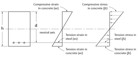
Fig no 14 Moment of resistance
Moment of resistance = tension force * lever arm
= T*Z
MR =  s t A s t (d- x/3)
Moment of resistance = compressive force
=C*Z
MR =  c b c/2 b x (d-x/3)
In flexural member
Moment of resistance helps to balance the bending moment due to loading
Key takeaways:
The basically design have different philosophy in which contains
Limit states methods
Working stress methods
Ultimate state methods
SINGLY REINFORCEMENT SECTION
BEAM
A beam is any structural member which resist load mainly by bending. Therefore, it is also called flexural member. beam may be singly reinforced or doubly reinforced. When steel is provided only in tensile zone
DESIGN CONSTANT OF MATERIAL GRADE
Tensile strength of concrete f ct < modulus of rupture f r
Compression stress of concrete f c << ½ f c
Tensile stress in steel f s< f y yield strength of steel
2. Stress elastic and section cracked
Tensile strength of concrete f ct > modulus of rupture
Compressive stress of concrete f c < ½ f c
Tensile stress in steel f s < f y yield strength of steel
SINGLY REINFORCED BEAM
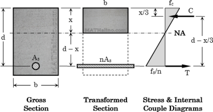
Fig no 15 Singly reinforced beam
Compression in concrete C = ½ f c b k d
Tension in steel T = A s f s
Equilibrium ∑F x = 0
Compression = tension
½ f c b k d = A s f s
Reinforcement ratio
 = A s / b d
f c / f s = 2  /k ……………………(1)
STRAIN COMPABLITY
 C /
C /  S = k d / d- k d = k/ 1-k
( fc /E c) /(f s/E s) = k/ 1-k
n f c /f s = k/ 1-k
Know  find k
K= )2 –n
)2 –n
Know f c, f sfind k
K = 1/1+ (f s/n f c )
MOMENT OF RESISTANCE
Moment arm distance: j d
J d = d – k d/3
J = 1- k/3
Steel
M = T * j d = A s f s j d
Concrete
M =C * j d = ½ f ck j b d2
R = ½ f c k j
DOUBLY REINFORCED BEAM
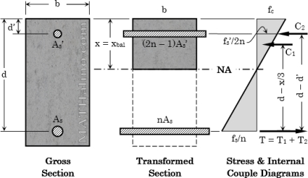
Fig no 16 Doubly reinforced section
Such reinforced concrete beams having steel reinforcement both on tensile and compressive faces are legendary as doubly bolstered beams. Doubly reinforced beams, therefore, have moment of resistance quite the singly reinforced beams of a similar depth for explicit grades of steel and concrete.
Lever arm constant
It is the distance between the compressive force and tensile force developed in the section due to flexural action in a R C member
It is denoted by z
Lever arm (z) = (d- x/3)
MOMENT OF RESISTANCE
M = M1 + M2
M1 = MC = ½ f c k j b d2
=A s 1 f s j d
A s 1 = M c / f s j d
M 2 = M – Mc
= A s 2 f s (d –d’)
= A s’ f s’ (d – d’)
A s 2 = M –M c/ f c (d –d’)
Area of steel
As = A s 1 + A s 2
STRAIN COMPRASIBILITY
 S/
S/  S’ = (d –k d)/(k d- d’)
From hook law,  s = E s f s ,
 s’= E s f s’
E s f s / E s fs’ = f s / f s’ = ( d- k d )/( k d – d ‘)
F s’ = f s( (k – d’)/d) /1-k
Design steps
Given data:
Size of beam, area of steel and grade of material
Step 1: Depth of critical neutral axis (x c).
X c / d- X c =  c b c/(
  s t/m )
Step 2: Actual depth of neutral axis (x),
b x2/2 = m A s t (d – x)
Step 3: Type of beam section,
1) X= X c, balanced section.
2) X < X c, under reinforced section.
3) X > X c, over reinforced section.
Step 4: Moment of resistance,
1) For under reinforced section
MR = T • Z
= σs t •A s t (d – x/3)
2) For over reinforced section
MR = C • Z
= (σc b c /2) •b x (d – x/3)
3) For balanced section
MR = T • Z = C • Z
Problem: -
1) A reinforced concrete beam section of size 300 mm x 700 mm effective depth is reinforced with 3 bars of 20 mm diameter in tension. The concrete mix and HYSD steel reinforcement used are of grade M20 and Fe415 respectively.
Find.
1) Depth of neutral axis.
2) Type of reinforced section.
3) Moment of resistance.
4) Maximum stress induced in material WSM is recommended.
Ans:
Given,
b = 300 mm
d = 700 mm
To find: x, MR and σc b c
Sol2
For M20, σc b c = 7 N/mm2and m = 280 / 3 *  c b c = 230/ 3* 7 = 13.33
For Fe415, σs t = 230 N/mm2
Area of steel = n *  /2 * d 2 = 942.5 mm 2
Step 1: Depth of critical neutral axis:
 c b c / (
 s t /m) = X c / (d –X c)
0.406 = X c / (700 – X c)
700 = x c + 2.464 X c
X C = 202
Step 2:Actual depth of neutral axis (x) :
= m. A s t( d – x)
= 13.33x942.5 (700– x)
150 x2 = 8.794 x 10⁶ – 12563.53x
150 x2 + 12563.53x - 8.794 x 106 = 0
Solving quadratic equation, we get
x = 203.85 mm
Step 3: Type of beam section:
Since, x > X c, then section is over reinforced section and will be fails
in compression.
Step 4: Moment of resistance:
MR = C* Z
MR =  c b c/ 2 .b .x. (d –
  x/3)
x/3)
= 300 X 203.85 (700–203.85 /3)
= 135.29 x 10⁶ N.mm = 135.29 KN.m
Step 5: maximum stress induced in material:
Since the section fails in compression,
 c b c max = 7 N/ mm 2
Corresponding maximum stress in steel:
=  c b c /
 s t/m) = x – (d-x)
= 93.33/  s t = 0.41086
 s t max= 227.1 N/mm2
Key take ways
Design of reinforced section by working stress methods find
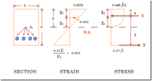
F y/1.15Es + 0.002 f y
SINGLY REINFORCEMENT BEAM
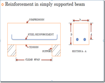
Fig no 17 Singly supported beam
X = depth of section
b = breadth of section
d = effective depth of section
The depth of neutral axis is obtained by considering the equilibrium of the traditional forces that is,
Resultant force of compression = average stress X area= 0.36 f c k b x
Resultant force of tension = 0.87 f y A t
Force of compression ought to be capable force of tension,
0.36 f c k b x = 0.87 f y A t
The distance between the lines of action of 2 forces C & T is termed the lever arm and is denoted by z.
Lever arm z = d – 0.42 x
z = d – 0.42
z = d – (f y A t/f c k b)
Moment of resistance with relevance concrete = compressive force x lever arm= 0.36 f c k b x z
Moment of resistance with respect to steel = tensile force x lever arm
= 0.87 f y A t z
Maximum depth of neutral axis
X m / (d – X m ) = 0.0035/ ((0.87 f y /E s )+ 0.002 )
X m /d = 0.0035 / ((0.87 f y / E s )+ 0.0055)
f y N/mm2 | X m |
250 | 0.53 d |
415 | 0.48 d |
500 | 0.46 d |
Limiting value of tension steel and moment of resistance
Limiting moment of resistance values, N mm
Grade of concrete | Grade | Of | Steel |
| Fe 250 | Fe 450 | Fe 500 |
General | 0.148 f c k b d2 | 0.138 f c k b d2 | 0.133 f c k b d2 |
M 20 | 2.96 b d2 | 2.76 b d2 | 2.66 b d2 |
M 25 | 3.70 b d2 | 3.45 b d2 | 3.33 b d2 |
M 30 | 4.44 b d2 | 4.14 b d2 | 3.99 b d2 |
SAMPLE NUMERICAL
Design of a section
Design of rectangular beam to resist a bending moment capable 45 kN m victimization. (1) M15 combine and delicate steel.
The beams are designed in order that below the applied moment each material reach their maximum stresses.
Assume quantitative relation of overall depth to breadth of the beam capable two
Breadth of the beam = b
Overall depth of beam = D
Therefore, D/b =
The balanced design,
Factored BM = moment of resistance with relevance concrete
= moment of resistance with respect to steel
= ratio X B.M
= 1.5 X 45= 67.5 kNm
For balanced section,
Moment of resistance Mu = 0.36 f c k b X m(d - 0.42 X m)
F y | X m |
250 | 0.53 d |
415 | 0.48 d |
Grade for steel is Fe250For Fe250
For Fe 250 steel,
X m= 0.53d
Mu = 0.36 f c k b (0.53 d) (1 – 0.42 * 0.53) d
= 2.22bd
Since D/b =2 or, d/b = 2 or, b=d/2
Mu = 1.11 d
Mu = 67.5 X ten N mm
d=394 mm and b= 200mm
Adopt D = 450 mm, b = 25 mm, d = 415 mm
Area of tensile steel At = Factored BM /0.87 f y (d -0.42 X m)
= 67.5 * 103 /0.87 * 250 * (1- 0.42 * 0.53 ) 415
In beams the diameter of main strengthened bars is typically hand-picked between twelve mm and 25 mm. Provide 2-20mm and 1-22mm bars giving total area
= 6.28 + 3.80
=10.08 cm > 9.62 cm
DOUBLY REINFORCEMENT BEAM:
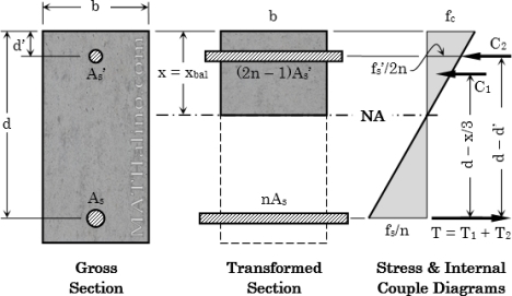
Fig no 18 Doubly reinforced section
If the applied bending moment is bigger than the instant resisting capability or final moment carrying capability of the section (I. e, over strengthened section), then there are often 3 alternatives:
1) If attainable, increase the size of the section, preferred 'depth
2) Use higher grade of concrete
3) Steel reinforcement is also more in compression zone to extend the instant resisting capability of the section (depth is stay because it is). This is often called a doubly reinforced beam'.
The double reinforced section is often needed underneath the subsequent circumstances:
1) Sectional dimensions area unit restricted thanks to needs ofhead room, look etc. and therefore the strength of given on an individual basis strengthened section is insufficient.
2) The beam that acts as a flanged beam at middle span becomes a rectangular beam at supports of a nonstop beam. At support tension happens at prime creating the projection ineffective and there for the section becomes inadequate to resist giant peak price of support moment,
4) Basement with lower support level and combined with ventilator couples and to style a double strengthened beam.
5) Compression steel is provided typically to scale back the deflection i.e. lo increase the stiffness and additionally to extend the rotation capability.
6) Compression steel is often utilized in structures in earthquake regions to extend their ductility
7) Compression reinforcement also will and considerably in reducing the future deflection of beams.
The failure theory evolved for on an individual basis strengthened section holds smart for doubly strengthened beam also. The most assumption
1) Plane sections stay plain even when bending
2) R.C. sections in bending fail once the compressive strain within the concrete reaches the worth of zero.0035
3) The strain at any purpose in steel and concrete is taken as adequate the strain resembling the strain at that time of the strain v/s strain graph for the fabric (steel or concrete)
4) X u limited / d' magnitude relation needn't be strictly adhered to in double strengthened beams
5) Even supposing shrinkage, creep and alternative properties of concrete wil have an effect on the particular stat of stress of steel and concrete, these aren't taken into thought in estimating the collapse or final strength
A doubly reinforced section may be looks upon as made up of 2 sections 1 and 2 gives below
Section 1
A singly reinforced section with concrete resisting compressive force c balanced by tensile force t provided by tension steel. this section is assumed so resist part moment
Section2
An imaginary section consisting of compression steel providing additional compression forces which is balanced by tensile force given by tension steel. This section is assumed to resist balancing moment M
DESIGN STEPS
Given
Grade of concrete
Grade of steel
Size of beam
Reinforcement provided
If X u = X u max …………….balanced
If X u< X u max …………….under reinforced
If X u> X u max …………….over reinforced
Equating the compression force and tension force
0.36 * f c k * b * X u * + A s c * f s c = 0.87 * f y * A s t
From this find X u
M u = 0.36 * f c k * b * X u * (d- 0.42 * X u) + A s c * f s c * (d- d’)
This equation is valid for balanced and under reinforced section
If the section is over reinforced section then take X u = X u max in above equation and use the same equation for finding M u. Do not increase the depth of the beam for over reinforced section.
Given
Grade of concrete and steel
Size of beam
Ultimate moment
M u is given
For balanced section X u = X u max
M u limiting = 0.36 * f c k * b * X u max * (d- 0.42 * X u max)
So M u 2 = M u – M u limiting
A s t limit = M u limit / 0.87 * f y * (d – 0.42 * X u max)
A sc = M u2/ f s c (d- d’)
As t 2 = A s c * f s c/ 0.87 f y
As t =A s t limit + A s t 2
Where
d = effective depth of beam
d’= distance between extreme compression fiber to the center of comp reinforced
b = width of beam
X u = depth of actual neutral axis
X u max = depth of critical neutral axis
A s t = total area of tensile reinforced in mm2
F c k = characteristic compressive strength of concrete
F y = characteristic strength of steel
M u limit = limiting M R of a section without compression reinforced in K N m
M u = ultimate M R
A s c= area of compression reinforcement
T BEAM
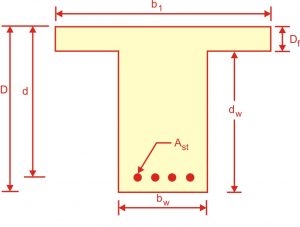
FIG NO 19 T BEAM
A beam is considered as such even if it has a large base to accommodate tension steel
The shape and size of concrete on the tension side assumed to be cracked has no effect on the theoretical moments
R C floors normally consist of slabs and beams that are cast monolithically the two acting together to resist load and because of this interaction the effective section of beam is a T or L beam
The effective flanged width resulting from slab interaction depend on slab type
Effective flanged beam
Exterior beam
Interior beam
Location of neutral axis and rectangular stress block depth
If the stress block falls in the flanged as is very frequent for positive moments the rectangular beam formula apply
In this case tensile concrete is assumed to be cracked and its shapes has no effect
The section is analysis as a rectangular one using the flanged b = bf
Minimum steel for T beam
Minimum steel quantity is imposed by codes for the same reasons as in rectangular beams
A s min =Max [( / 4 f y), (1.4 / f y)] * b w * d
Analysis of T beams
Analysis steps for T beams
As f y/0.85 f y b f
If a <= h f stress block in flanged
If a >= h f stress block in web


L BEAM
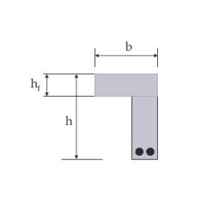
Fig no 20 L BEAM
In bending the beam take the tension force and slab take compression force since the L beam receive their load from one side only they are subjected to consideration amount of torsion moments so L beam are subjected to bending moments shear force and torsion moments
Moment carried by flange of L beams
The moment M1 causes torsion in the beam and is known as the torsion moments which is restricted by the rectangular portion only and the flanged does not contribute to torsion moment of resistance
Moment carried by flanged of L beam and the slab
The central load W cause bending moments in the beam which is joined restricted by the rectangular portion of the beam as well as the flanged
Changes in floor level may be accommodated by either an L beam or building up one side of an inverted T beam
Code recommends that effective width of the flanged of beam may be taken as follows
2. for isolated L beams, lesser of
Where
b f = effective width of flanged
b w =breadth of rib
b = actual width of flanged
I o = distance between points of zero moments in beam
The design principles to be followed while designing L beam
Given
Step 1: determine width of flanged
Steps 2: fixed up a suitable depth
Steps 3: calculate MR of the section assuming the failure of concrete to occur .if the moment of resistance is greater than bending moments assumed depth is ok otherwise either increases the depth of the section or provide additional reinforcement in compression side in addition to the tension side
Steps 4: calculate the amount of tension steel for actual bending moments treating it as a balanced section
Steps 5: check for the shear and provide shear reinforced
Steps 6: check of deflection
Steps 7: check for end anchoring and development length
Key takeaways:
In this point we see single reinforced and doubly reinforced beam by LSM method and also the T section beam and L section beam
In this method also same parameter is calculating
References


