Unit - 3
Introduction to Fluid Mechanics and Applications
Properties of Fluid
Any characteristic of a system is called property. It may either be intensive (mass independent) or extensive (that depends on size of system). The state of a system is described by its properties. The number of properties required to fix the state of the system is given by state postulates. Most common properties of the fluid are:
1. Pressure (p): It is the normal force exerted by a fluid per unit area. More details will be available in the subsequent section (Lecture 02). In SI system the unit and dimension of pressure can be written as, N/m2 and  respectively.
2. Density: The density of a substance is the quantity of matter contained in unit volume of the substance. It is expressed in three different ways; mass density mass volume,  specific weight (ρg) and relative density/specific gravity water.
 The units and dimensions are given as, For mass density; Dimension:
  Unit: kg/m3
For specific weight; Dimension:  Unit: N/m3
The standard values for density of water and air are given as 1000kg/m3 and 1.2 kg/m3, respectively. Many a times the reciprocal of mass density is called as specific volume (v).
Kinematic viscosity
In fluid dynamics, it is sometimes more convenient to work in terms of the kinematic viscosity (sometimes also called the momentum diffusivity), defined as the ratio of the viscosity μ to the density of the fluid ρ. It is usually denoted by the Greek letter nu (ν) and has dimension :
Kinematic Viscosity v = μ/ 
Where
V = Kinematic viscosity
μ= Dynamic viscosity
 = Density of the liquid
Dynamic Viscosity
Dynamic viscosity is the force needed by a fluid to overcome its own internal molecular friction so that the fluid will flow. In other words, dynamic viscosity is defined as the tangential force per unit area needed to move the fluid in one horizontal plane with respect to other plane with a unit velocity while the fluid's molecules maintain a unit distance apart.
Dynamic viscosity is also referred as absolute viscosity in the field of fluid mechanics.
Specific Gravity or relative gravity is a dimensionless quantity that is defined as the ratio of the density of a substance to the density of the water at a specified temperature and is expressed as
SG =  substance/
  H2O
H2O
It is common to use the density of water at 4 oC as a reference point as water at this point has the highest density of 1000 kg/m3.
Newtonian Fluids
Newtonian fluids are named after Sir Issac Newton (1642 - 1726) who described the flow behavior of fluids with a simple linear relation between shear stress [mPa] and shear rate [1/s]. This relationship is now known as Newton's Law of Viscosity, where the proportionality constant η is the viscosity [mPa-s] of the fluid:

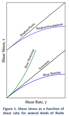
Some examples of Newtonian fluids include water, organic solvents, and honey. For those fluids viscosity is only dependent on temperature. As a result, if we look at a plot of shear stress versus shear rate (See Figure 1) we can see a linear increase in stress with increasing shear rates, where the slope is given by the viscosity of the fluid. This means that the viscosity of Newtonian fluids will remain a constant (see Figure 2) no matter how fast they are forced to flow through a pipe or channel (i.e. viscosity is independent of the rate of shear).
An exception to the rule is Bingham plastics, which are fluids that require a minimum stress to be applied before they flow. These are strictly non-Newtonian, but once the flow starts, they behave essentially as Newtonian fluids (i.e. shear stress is linear with shear rate). A great example of this kind of behavior is mayonnaise.
Newtonian fluids are normally comprised of small isotropic (symmetric in shape and properties) molecules that are not oriented by flow. However, it is also possible to have Newtonian behavior with large anisotropic molecules. For example, low concentration protein or polymer solutions might display a constant viscosity regardless of shear rate. It is also possible for some samples to display Newtonian behavior at low shear rates with a plateau known as the zero-shear viscosity region.
Non-Newtonian Fluids
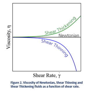
In reality most fluids are non-Newtonian, which means that their viscosity is dependent on shear rate (Shear Thinning or Thickening) or the deformation history (Thixotropic fluids). In contrast to Newtonian fluids, non-Newtonian fluids display either a non-linear relation between shear stress and shear rate (see Figure 1), have a yield stress, or viscosity that is dependent on time or deformation history (or a combination of all the above!).
A fluid is shear thickening if the viscosity of the fluid increases as the shear rate increases (see Figure 2). A common example of shear thickening fluids is a mixture of cornstarch and water. You have probably seen examples of this on TV or the internet, where people can run over this kind of solutions and yet, they will sink if they stand still. Fluids are shear thinning if the viscosity decreases as the shear rate increases. Shear thinning fluids, also known as pseudo-plastics, are ubiquitous in industrial and biological processes. Common examples include ketchup, paints and blood.
Non-Newtonian behavior of fluids can be caused by several factors, all of them related to structural reorganization of the fluid molecules due to flow. In polymer melts and solutions, it is the alignment of the highly anisotropic chains what results in a decreased viscosity. In colloids, it is the segregation of the different phases in the flow that causes a shear thinning behavior.
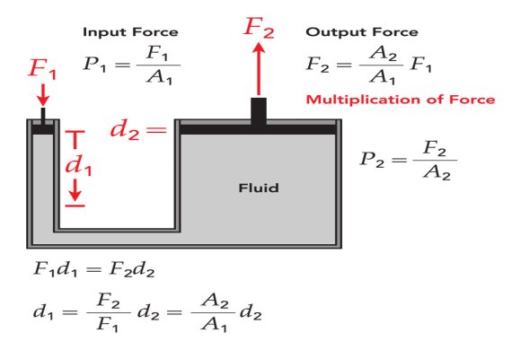
Pascal's principle applies to incompressible fluids. One typical application can be found in most automotive repair shops that have a lift. Basically, air from an air compressor is applied to the top of the oil in a container and the oil then applies pressure to a sleeve/piston that lifts the car. This is the same principle found when using a hydraulic jack at home. However, the smaller cylinder must travel much farther than the larger lift cylinder.
This allows the lifting of a heavy load with a small force, as in an auto hydraulic life, but of course there can be no multiplication of work, so in an ideal case with no friction loss:
When a fluid is in motion, it must move in such a way that mass is conserved. To see how mass conservation places restrictions on the velocity field, consider the steady flow of fluid through a duct (that is, the inlet and outlet flows do not vary with time). The inflow and outflow are one-dimensional, so that the velocity V and density \rho are constant over the area A (figure 14).
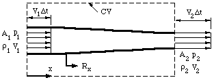
Figure. One-dimensional duct showing control volume.
Now we apply the principle of mass conservation. Since there is no flow through the side walls of the duct, what mass comes in over A_1 goes out of A_2, (the flow is steady so that there is no mass accumulation). Over a short time interval \Delta t,
Volume flow in over A1 = A1 V1 ∆t
Volume flow out over A2 = A2 V2 ∆t
Therefore
Mass in over A =  A1 V1 ∆t
Mass out over A =  A2 V2 ∆t
So  A1 V1 ∆t =
  A2 V2 ∆t
This is a statement of the principle of mass conservation for a steady, one-dimensional flow, with one inlet and one outlet. This equation is called the continuity equation for steady one-dimensional flow. For a steady flow through a control volume with many inlets and outlets, the net mass flow must be zero, where inflows are negative and outflows are positive.
Bernoulli’s principle states that
The total mechanical energy of the moving fluid comprising the gravitational potential energy of elevation, the energy associated with the fluid pressure and the kinetic energy of the fluid motion, remains constant.
Bernoulli’s Principle Formula
Bernoulli’s equation formula is a relation between pressure, kinetic energy, and gravitational potential energy of a fluid in a container.
The formula for Bernoulli’s principle is given as:
p + 12 ρ v2 + ρgh =constant
Where,
Bernoulli’s equation gives great insight into the balance between pressure, velocity and elevation.
Problem: A horizontal pipe of non-uniform cross-section allows water to flow
through it with a velocity 1 ms−1 when pressure is 50 kPa at a point. If the velocity of flow has to be 2 ms−1 at some other point, what will the pressure at that point?
Solution:
Applying Bernoulli's equation at point 1 and point 2,
⇒P1+21ρ1V12=P2+21ρ2V22
⇒50×103+21×103(1)2=P2+21×103×4
⇒5×10⁴+500−2000=p2
⇒P2=48.5 kPa
Hydraulic Turbine is the main prime over which helps to converts hydraulic energy into electrical energy by the help of a generator. When a stream of water is hit the blades of the turbine, it forces the turbine to rotate hence there is a generator fitted with the turbine so the generator has also come in rotation and produces the electrical energy.
Classification of Hydraulic Turbines:
The hydraulic Turbines were classified according to the following conditions.
An Explanation for the Classification of Hydraulic Turbines is as follows.
1. Classification of Turbine based on the direction of flow of water:
Tangential Flow:
If the water strikes the blades of the runner tangential to the path of rotation called Tangential flow.
For example, Pelton wheel turbine.
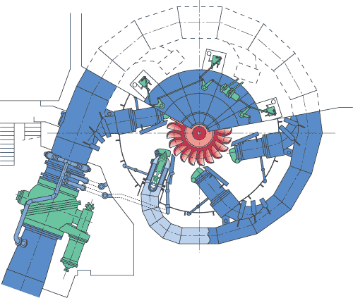
By Voith Siemens Hydro Power Generation, Sectional view of Pelton wheel turbine.
Radial Flow:
If the water strikes the blades of the runner radially and coming out axially called as Radial flow.
For example, Francis turbine Side view
Axial Flow:
In this flow, the water flows parallel to the axis of the turbine.
For example, Kaplan turbine
By Voith Hydro Power Generation, A schematic diagram of kaplan turbine
2. Classification of Turbine based on Available head:
The turbine capable of working under the high potential head of water above 300m
For example, Pelton wheel turbine.
The turbine is capable of working under a medium range of potential head about 60m to 300m
For example, Francis turbine.
The turbine is capable of working under a low range of potential head less than 60m
3. Classification of Turbine based on Specific speed:
Low Specific Speed:
Turbine works in the range of 10-50.
For example, Pelton wheel turbine
Medium Specific Speed:
Turbine works in the range of 50-350.
For example, Francis turbine
High Specific Speed:
Turbine works in the range of 250-850.
For example, Kaplan turbine
4. Classification of Turbine based on Action of water:
There is no pressure drop on the runner or rotor. Kinetic Energy of water coming from the jet is used to run the runner or rotor.
For example, Pelton wheel turbine.
Reaction:
There is a loss of Kinetic Energy as well as pressure energy on the runners of the blade.
For example, Francis turbine
Accumulators usually are installed in hydraulic systems to store energy and to smooth out pulsations. Typically, a hydraulic system with an accumulator can use a smaller pump because the accumulator stores energy from the pump during periods of low demand. This energy is available for instantaneous use, released upon demand at a rate many times greater than what could be supplied by the pump alone.

Accumulators also can act as surge or pulsation absorbers, much as an air dome is used on pulsating piston or rotary pumps. Accumulators will cushion hydraulic hammer, reducing shocks caused by rapid operation or sudden starting and stopping of power cylinders in a hydraulic circuit.
There are four principal types of accumulators: the weight-loaded piston type, diaphragm (or bladder) type, spring type, and the hydro-pneumatic piston type. The weight-loaded type was the first used, but is much larger and heavier for its capacity than the modern piston and bladder types. Both weighted and spring types are infrequently found today. Hydro-pneumatic accumulators, Figure 1, are the type most commonly used in industry.
Functions
Energy storage — Hydro pneumatic accumulators incorporate a gas in conjunction with a hydraulic fluid. The fluid has little dynamic power-storage qualities; typical hydraulic fluids can be reduced in volume by only about 1.7% under a pressure of 5,000 psi. (However, this relative incompressibility makes them ideal for power transmission, providing quick response to power demand.) Therefore, when only 2% of the total contained volume is released, the pressure of the remaining oil in the system drops to zero.
On the other hand, gas, the partner to the hydraulic fluid in the accumulator, can be compressed into small volumes at high pressures. Potential energy is stored in the compressed gas to be released upon demand. Such energy can be compared to that of a raised pile driver ready to transfer its tremendous energy upon the pile. In the piston type accumulator, the energy in the compressed gas exerts pressure against the piston separating the gas and hydraulic fluid. The piston in turn, forces the fluid from the cylinder into the system and to the location where useful work will be accomplished.
Pulsation absorption - Pumps, of course, generate the required power to be used or stored in a hydraulic system. Many pumps deliver this power in a pulsating flow. The piston pump, commonly used for its high pressure capability, can produce pulsations detrimental to a high-pressure system. An accumulator properly located in the system will substantially cushion these pressure variations.
Shock cushioning - In many fluid power applications, the driven member of the hydraulic system stops suddenly, creating a pressure wave that travels back through the system This shock wave can develop peak pressures several times greater than normal working pressures. It can cause objectionable noise or even system failure. An accumulator's gas cushion, properly located in the system, will minimize this shock.
An example of this application is the absorption of shock caused by suddenly stopping the loading bucket on a hydraulic front end loader. Without an accumulator, the bucket, weighing over 2 tons, can completely lift the rear wheels of a loader off the ground. The severe shock to the tractor frame and axle, as well as operator wear and tear, is overcome by adding an adequate accumulator to the hydraulic system.
Supplementing pump flow - An accumulator, capable of storing power can supplement the hydraulic pump in delivering power to the system. The pump stores potential energy in the accumulator during idle periods of the work cycle. The accumulator transfers this reserve power back to the system when the cycle requires emergency or peak power. This enables a system to utilize a much smaller pump, resulting in savings in cost and power.
Maintaining pressure - Pressure changes occur in a hydraulic system when the liquid is subjected to rising or falling temperatures. Also, there may be pressure drop due to leakage of hydraulic fluid. An accumulator compensates for such pressure changes by delivering or receiving a small amount of hydraulic fluid. If the main power source should fail or be stopped, the accumulator would act as an auxiliary power source, maintaining pressure in the system.
Fluid dispensing - An accumulator may be used to dispense small volumes of fluids, such as lubricating greases and oils, on command.
Mounting position
The optimum mounting position for any accumulator is vertical with the hydraulic port down. Piston models can be horizontal if the fluid is kept clean. When solid contaminants are present or expected in significant amounts, horizontal mounting can result in uneven or accelerated seal wear. Maximum service life can be achieved in the horizontal position with multiple piston seals to balance the piston's parallel surface.
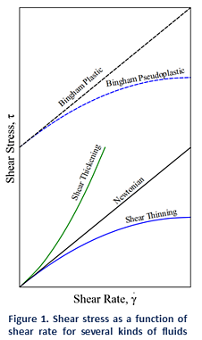
Fig. Horizontally mounted accumulators can cause uneven bladder wear and trap fluid away from the hydraulic valve.
A bladder accumulator also can be mounted horizontally, Figure 2, but uneven wear on the bladder as it rubs against the shell while floating on the fluid can shorten life. The amount of damage depends on fluid cleanliness, cycle rate, and compression ratio (defined as maximum-system-pressure/ minimum-system-pressure). In extreme cases, fluid can be trapped away from the hydraulic end, which reduces output or may elongate the bladder to force the poppet closed prematurely.
Accumulator applications
Accumulators are also used for systems where thermal expansion could cause excessive pressure. Cylinders with blocked ports in a high ambient heat area can go to high pressure if there is no place for expanding fluid to go.
Another use for accumulators is as a barrier between two different fluids. The pump that uses hydraulic fluid keeps pressure on a circuit that uses water or another incompatible medium. One supplier offers low-pressure accumulators as breathing devices for sealed reservoirs. This keeps airborne contaminants out of the hydraulic oil as the fluid level rises and falls.
Key takeaways:
1) Accumulators are also used for systems where thermal expansion could cause excessive pressure
2) A hydraulic system with an accumulator can use a smaller pump because the accumulator stores energy from the pump during periods of low demand
Hydraulic systems are used for all sorts of things from car braking systems to forklift trucks, presses to pumps. All the systems use the same basic principle, and hydraulic lifts are no different.
The main components of a hydraulic elevator are:
Usually, a hydraulic lift will have a machine room, which will house the pump, fluid and motor, so you may need more space than expected. You can get machine-room-less (MRL) hydraulic lifts which generally house the machinery and such within the shaft, against the guides that run behind the lift, making them a more space-saving option.
Hydraulic Lifts Working
Hydraulic lifts work on a basic principle: to go up, a pump pushes oil into the cylinder, pushing the piston (which pushes the lift car) up. To go down, the valve opens and oil is allowed to flow back into the reservoir, and is pushed back using the gravitational force of the lift car.
When the valve is closed, the oil can only go from the reservoir into the cylinder. When the valve is open, the oil can only flow from the cylinder back into the reservoir. The controls in the lift car make the pump operate, moving the oil. When a floor is reached, the pump is switched off and the lift car sits on top of the piston, held in position by the oil which is trapped in the cylinder.
Even automobile brakes use hydraulics. When you push the brake pedal, it pushes a small piston in the brake master cylinder. The piston applies pressure on the brake fluid, which transfers the pressure through the brake lines, forcing another set of pistons to force the brake linings into contact with the brake drums on each wheel. The resulting friction of brake lining against brake drum slows the car down, eventually stopping the car
The position, size and operation of the cylinder can be one of two options – ‘holed’ or ‘hole-less’
A holed hydraulic lift is a conventional hydraulic lift. ‘Holed hydraulic’ refers to the hole required in the floor for the lift. The cylinder which encases the piston and pushes the lift car extends into the ground. The distance this extends is equal to the distance the lift car can travel upwards.
A hole-less hydraulic lift means no need for a deep pit for the cylinder. The pistons are direct action, and are mounted on the floor of the pit in line with the bottom corners of the lift car. The system operates like a jack, and restricts travel to around 20-30m at most. This is not as common but allows for use where space is restricted going down, travel is short and a hydraulic system is required.
Pros & Cons of Hydraulic Lifts
To help when choosing a lift, it is worth taking into account the benefits and limitations in relation to your requirements. Different environments, travel heights, usage levels and space available can be a deciding factor.
PROS
With the machine room holding all the machinery, you won’t need space above the shaft to hold machinery (which traction lifts do). The system is also supported by the floor/pit so should not need any kind of reinforcement.
The classic ‘dead drop’ situation is not possible in a hydraulic lift as there are no cables – though this doesn’t often happen in reality. If the system breaks, then the lift will only drop at the speed which oil can leak from the system.
Finally, hydraulic lifts are cheaper than traction lifts so if budget is key then this could help make the decision.
CONS
It is worth looking at the travel distance as a hydraulic lift system is quite slow (up to 1m/s). It may not be suitable over 6-8 floors – also due to requiring further underground space to house the cylinder.
Space required for a machine room and oil pit if required might not be suitable in all buildings, especially where floor space is at a premium. Digging down for holed systems can mean going very deep underground which may not always be possible.
Hydraulic systems rely on the oil, which operates differently at different temperatures (oil gets thinner at higher temperatures) so a good system can help balance this effect.
As with any fluid, oil can leak out of the system which can cause big issues. This doesn’t tend to happen to new systems but keeping your lift maintained properly is vital.
Finally, if you are looking to meet BREEAM or energy efficiency ratings, hydraulic lifts are less energy efficient than other types of lift. The power required to raise the lift car is high, as the oil is doing all the work fighting against gravity. Alternatives, such as traction lifts, use a counterweight so require less energy.
Key takeaways
1) Hydraulic lifts work on a basic principle: to go up, a pump pushes oil into the cylinder, pushing the piston (which pushes the lift car) up. To go down, the valve opens and oil is allowed to flow back into the reservoir, and is pushed back using the gravitational force of the lift car.
2) When the valve is closed, the oil can only go from the reservoir into the cylinder.
3) When the valve is open, the oil can only flow from the cylinder back into the reservoir
References:
1. Basic Mechanical Engineering, G Shanmugam, S Ravindran, McGraw Hill
2. Basic Mechanical Engineering, M P Poonia and S C Sharma, Khanna Publishers
3. Mechatronics: Principles, Concepts and Applications, Nitaigour Mahalik, McGraw Hill
4. Mechatronics, As per AICTE: Integrated Mechanical Electronic Systems, K.P. Ramachandran, G.K. Vijayaraghavan, M.S. Balasundaram, Wiley India
5. Mechanical Measurements & Control, Dr. D. S. Kumar. Metropolitan Book Company