UNIT 5
I/O Management and Disk Scheduling
Operating System - I/O Hardware
One of the necessary jobs of associate software is to manage numerous I/O devices together with the mouse, keyboards, touchpad, disk drives, show adapters, USB devices, Bit-mapped screen, LED, analog-digital converter, On/off switch, network connections, audio I/O, printers, etc.
An I/O system is needed to require associate application I/O request and send it to the physical device, then take no matter response comes back from the device and send it to the applying. I/O devices may be divided into 2 classes classes
• Block devices − A block device is one with that the driving force communicates by causing entire blocks of knowledge. For instance, Hard disks, USB cameras, Disk-On-Key, etc.
• Character devices − a personality device is one with that the driving force communicates by causing and receiving single characters (bytes, octets). For instance, serial ports, parallel ports, sounds cards, etc
Device Controllers
Device drivers square measure computer code modules that will be obstructed into the associate OS to handle a particular device. The software takes facilitate from device drivers to handle all I/O de-vices.
The Device Controller works like an associate interface between a tool and a tool driver. I/O units (Keyboard, mouse, printer, etc.) generally accommodate a mechanical part associated with an electronic part wherever the electronic part is named the device controller.
There is invariably a tool controller and a tool driver for every device to communicate with the operational Systems. a tool controller could also be able to handle multiple devices. As associate interface its main task is to convert serial bit stream to the dam of bytes, perform error correction as necessary.
Any device connected to the pc is connected by a plug and socket, and therefore the socket is connected to a tool controller. The following could be a model for connecting the central processor, memory, controllers, and I/O devices wherever central processor and device controllers all use a standard bus for communication.
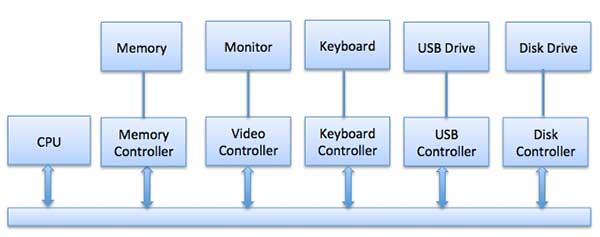
Fig 1- The model for connecting the central processor, memory, controllers, and I/O devices
Synchronous vs asynchronous I/O
- Synchronous I/O − In this scheme CPU execution waits while I/O proceeds
- Asynchronous I/O − I/O proceeds concurrently with CPU execution
Communication to I/O Devices
The CPU must have a way to pass information to and from an I/O device. There are three approaches available to communicate with the CPU and Device.
- Special Instruction I/O
- Memory-mapped I/O
- Direct memory access (DMA)
Special Instruction I/O
This uses CPU instructions that are specifically made for controlling I/O devices. These instructions typically allow data to be sent to an I/O device or read from an I/O device.
Memory-mapped I/O
When using memory-mapped I/O, the same address space is shared by memory and I/O devices. The device is connected directly to certain main memory locations so that the I/O device can transfer a block of data to/from memory without going through the CPU.
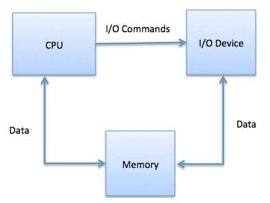
Fig 2 - Memory without going through CPU
While using memory-mapped IO, OS allocates a buffer in memory and informs the I/O device to use that buffer to send data to the CPU. I/O device operates asynchronously with CPU, interrupts CPU when finished.
The advantage of this method is that every instruction which can access memory can be used to manipulate an I/O device. Memory-mapped IO is used for most high-speed I/O devices like disks, communication interfaces.
Direct Memory Access (DMA)
Slow devices like keyboards will generate an interrupt to the main CPU after each byte is transferred. If a fast device such as a disk generated an interrupt for each byte, the operating system would spend most of its time handling these interrupts. So a typical computer uses direct memory access (DMA) hardware to reduce this overhead.
Direct Memory Access (DMA) means CPU grants I/O module authority to read from or write to memory without involvement. DMA module itself controls the exchange of data between the main memory and the I/O device. CPU is only involved at the beginning and end of the transfer and interrupted only after the entire block has been transferred.
Direct Memory Access needs special hardware called the DMA controller (DMAC) that manages the data transfers and arbitrates access to the system bus. The controllers are programmed with source and destination pointers (where to read/write the data), counters to track the number of transferred bytes, and settings, which include I/O and memory types, interrupts and states for the CPU cycles.
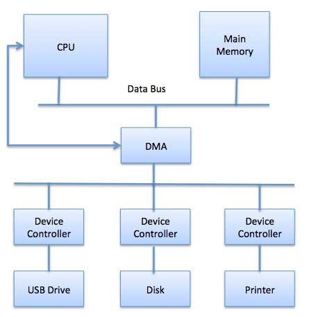
Fig 3 - DMA
The operating system uses the DMA hardware as follows −
Step | Description |
1 | A device driver is instructed to transfer disk data to a buffer address X. |
2 | The device driver then instructs the disk controller to transfer data to the buffer. |
3 | Disk controller starts DMA transfer. |
4 | The disk controller sends each byte to the DMA controller. |
5 | DMA controller transfers bytes to buffer, increases the memory address, decreases the counter C until C becomes zero. |
6 | When C becomes zero, the DMA interrupts the CPU to signal transfer completion. |
Polling vs Interrupts I/O
A computer must have a way of detecting the arrival of any type of input. There are two ways that this can happen, known as polling and interrupts. Both of these techniques allow the processor to deal with events that can happen at any time and that are not related to the process it is currently running.
Polling I/O
Polling is the simplest way for an I/O device to communicate with the processor. The process of periodically checking the status of the device to see if it is time for the next I/O operation is called polling. The I/O device simply puts the information in a Status register, and the processor must come and get the information.
Most of the time, devices will not require attention and when one does it will have to wait until it is next interrogated by the polling program. This is an inefficient method and much of the processor's time is wasted on unnecessary polls.
Compare this method to a teacher continually asking every student in a class, one after another, if they need help. The more efficient method would be for a student to inform the teacher whenever they require assistance.
Interrupts I/O
An alternative scheme for dealing with I/O is the interrupt-driven method. An interrupt is a signal to the microprocessor from a device that requires attention.
A device controller puts an interrupt signal on the bus when it needs the CPU’s attention when the CPU receives an interrupt, It saves its current state and invokes the appropriate interrupt handler using the interrupt vector (addresses of OS routines to handle various events). When the interrupting device has been dealt with, the CPU continues with its original task as if it had never been interrupted.
Operating System - I/O Software’s
I/O software is often organized in the following layers −
- User Level Libraries − This provides a simple interface to the user program to perform input and output. For example, stdin is a library provided by C and C++ programming languages.
- Kernel Level Modules − This provides a device driver to interact with the device controller and device-independent I/O modules used by the device drivers.
- Hardware − This layer includes actual hardware and hardware controller which interact with the device drivers and makes hardware alive.
A key concept in the design of I/O software is that it should be device-independent where it should be possible to write programs that can access any I/O device without having to specify the device in advance. For example, a program that reads a file as input should be able to read a file on a floppy disk, on a hard disk, or a CD-ROM, without having to modify the program for each different device.
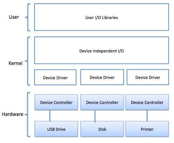
Fig 4 - Example
Device Drivers
Device drivers are software modules that can be plugged into an OS to handle a particular device. Operating System takes help from device drivers to handle all I/O devices. Device drivers encapsulate device-dependent code and implement a standard interface in such a way that code contains device-specific register reads/writes. The device driver is generally written by the device's manufacturer and delivered along with the device on a CD-ROM.
A device driver performs the following jobs −
- To accept request from the device-independent software above to it.
- Interact with the device controller to take and give I/O and perform required error handling
- Making sure that the request is executed successfully
How a device driver handles a request is as follows: Suppose a request comes to read a block N. If the driver is idle at the time a request arrives, it starts carrying out the request immediately. Otherwise, if the driver is already busy with some other request, it places the new request in the queue of pending requests.
Interrupt handlers
An interrupt handler, also known as an interrupt service routine or ISR, is a piece of software or more specifically a callback function in an operating system or more specifically in a device driver, whose execution is triggered by the reception of an interrupt.
When the interrupt happens, the interrupt procedure does whatever it has to handle the interrupt, updates data structures, and wakes up the process that was waiting for an interrupt to happen.
The interrupt mechanism accepts an address ─ a number that selects a specific interrupt handling routine/function from a small set. In most architectures, this address is an offset stored in a table called the interrupt vector table. This vector contains the memory addresses of specialized interrupt handlers.
Device-Independent I/O Software
The basic function of the device-independent software is to perform the I/O functions that are common to all devices and to provide a uniform interface to the user-level software. Though it is difficult to write completely device-independent software we can write some modules which are common among all the devices. Following is a list of functions of device-independent I/O Software −
- Uniform interfacing for device drivers
- Device naming - Mnemonic names mapped to Major and Minor device numbers
- Device protection
- Providing a device-independent block size
- Buffering because data coming off a device cannot be stored in the final destination.
- Storage allocation on block devices
- Allocation and releasing dedicated devices
- Error Reporting
User-Space I/O Software
These are the libraries that provide a richer and simplified interface to access the functionality of the kernel or ultimately interact with the device drivers. Most of the user-level I/O software consists of library procedures with some exception like spooling system which is a way of dealing with dedicated I/O devices in a multiprogramming system.
I/O Libraries (e.g., stdin) are in user-space to provide an interface to the OS resident device-independent I/O SW. For example putchar(), getchar(), printf() and scanf() are example of user-level I/O library stdin available in C programming.
Kernel I/O Subsystem
Kernel I/O Subsystem is responsible to provide many services related to I/O. Following are some of the services provided.
- Scheduling − Kernel schedules a set of I/O requests to determine a good order in which to execute them. When an application issues a blocking I/O system call, the request is placed on the queue for that device. The Kernel I/O scheduler rearranges the order of the queue to improve the overall system efficiency and the average response time experienced by the applications.
- Buffering − Kernel I/O Subsystem maintains a memory area known as a buffer that stores data while they are transferred between two devices or between a device with an application operation. Buffering is done to cope with a speed mismatch between the producer and consumer of a data stream or to adapt between devices that have different data transfer sizes.
- Caching − Kernel maintains cache memory which is a region of fast memory that holds copies of data. Access to the cached copy is more efficient than access to the original.
- Spooling and Device Reservation − A spool is a buffer that holds output for a device, such as a printer, that cannot accept interleaved data streams. The spooling system copies the queued spool files to the printer one at a time. In some operating systems, spooling is managed by a system daemon process. In other operating systems, it is handled by an in-kernel thread.
- Error Handling − An operating system that uses protected memory can guard against many kinds of hardware and application errors.
KEY TAKEAWAY
One of the necessary jobs of associate software is to manage numerous I/O devices together with the mouse, keyboards, touchpad, disk drives, show adapters, USB devices, Bit-mapped screen, LED, analog-digital converter, On/off switch, network connections, audio I/O, printers, etc.
An I/O system is needed to require associate application I/O request and send it to the physical device, then take no matter response comes back from the device and send it to the applying. I/O devices may be divided into 2 classes classes
I/O devices are very important in computer systems. They provide users the means of interacting with the system. So there is a separate I/O system devoted to handling the I/O devices.
The different Components of the I/O systems are −
I/O Hardware
There are many I/O devices handled by the operating system such as a mouse, keyboard, disk drive, etc. Different device drivers can be connected to the operating system to handle a specific device. The device controller is an interface between the device and the device driver.
A diagram to represent this is −
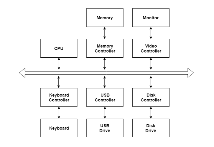
Fig 5 – I/O device
I/O Application Interface
The user applications can access all the I/O devices using the device drivers, which are device-specific codes. The application layer sees a common interface for all the devices.
This is illustrated using the below image −
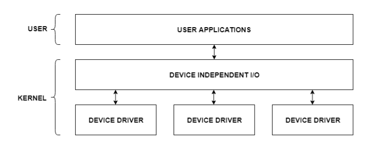
Fig 6 - Example
Most of the devices are either block I/O and character I/O devices. Block devices are accessed one block at a time whereas character devices are accessed one character at a time.
I/O Software
The I/O software contains the user-level libraries and the kernel modules. The libraries provide the interface to the user program to perform input and output. The kernel modules provide the device drivers that interact with the device controllers.
The I/O software should be device-independent so that the programs can be used for any I/O device without specifying it in advance. For example - A program that reads a file should be able the read the file on a hard disk, floppy disk, CD-ROM, etc. without having to change the program each time.
KEY TAKEAWAY
I/O devices are very important in computer systems. They provide users the means of interacting with the system. So there is a separate I/O system devoted to handling the I/O devices.
A buffer is a memory area that stores data being transferred between two devices or between a device and an application.
Uses of I/O Buffering:
- Buffering is done to deal effectively with a speed mismatch between the producer and consumer of the data stream.
- A buffer is produced in main memory to heap up the bytes received from the modem.
- After receiving the data in the buffer, the data get transferred to disk from buffer in a single operation.
- This process of data transfer is not instantaneous, therefore the modem needs another buffer to store additional incoming data.
- When the first buffer got filled, then it is requested to transfer the data to disk.
- The modem then starts filling the additional incoming data in the second buffer while the data in the first buffer getting transferred to the disk.
- When both the buffers completed their tasks, then the modem switches back to the first buffer while the data from the second buffer get transferred to the disk.
- The use of two buffers disintegrates the producer and the consumer of the data thus minimizes the time requirements between them.
- Buffering also provides variations for devices that have different data transfer sizes.
Types of various I/O buffering techniques:
1. Single buffer:
A buffer is provided by the operating system to the system portion of the main memory.
Block oriented device –
- System buffer takes the input.
- After taking the input, the block gets transferred to the user space by the process, and then the process requests for another block.
- Two blocks work simultaneously, when one block of data is processed by the user process, the next block is being read in.
- OS can swap the processes.
- OS can record the data of system buffer to user processes.
Stream oriented device –
- Line- at a time operation is used for scroll made terminals. The user inputs one line at a time, with a carriage return signaling at the end of a line.
- Byte-at a time operation is used on forms mode, terminals when each keystroke is significant.

Fig 7 – Simple I/O Buffering
2. Double buffer:
Block oriented –
- There are two buffers in the system.
- One buffer is used by the driver or controller to store data while waiting for it to be taken by a higher level of the hierarchy.
- Another buffer is used to store data from the lower-level module.
- Double buffering is also known as buffer swapping.
- A major disadvantage of double buffering is that the complexity of the process gets increased.
- If the process performs rapid bursts of I/O, then using double buffering may be deficient.
Stream oriented –
- Line- at a time I/O, the user process need not be suspended for input or output, unless the process runs ahead of the double buffer.
- Byte- at a time operation, double buffer offers no advantage over a single buffer of twice the length.

Fig 8 – Double I/O Buffering
3. Circular buffer:
- When more than two buffers are used, the collection of buffers is itself referred to as a circular buffer.
- In this, the data do not directly pass from the producer to the consumer because the data would change due to overwriting of buffers before they had been consumed.
- The producer can only fill up to buffer i-1 while data in buffer i is waiting to be consumed.
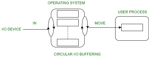
Fig 9 – Circular I/O Buffering
KEY TAKEAWAY
A buffer is a memory area that stores data being transferred between two devices or between a device and an application.
Uses of I/O Buffering:
- Buffering is done to deal effectively with a speed mismatch between the producer and consumer of the data stream.
- A buffer is produced in main memory to heap up the bytes received from the modem.
- After receiving the data in the buffer, the data get transferred to disk from buffer in a single operation.
As we know, a process needs two types of time, CPU time, and IO time. For I/O, it requests the Operating system to access the disk.
However, the operating system must be fair enough to satisfy each request and at the same time, the operating system must maintain the efficiency and speed of process execution.
The technique that the operating system uses to determine the request which is to be satisfied next is called disk scheduling.
Let's discuss some important terms related to disk scheduling.
Seek Time
Seek time is the time taken in locating the disk arm to a specified track where the read/write request will be satisfied.
Rotational Latency
It is the time taken by the desired sector to rotate itself to the position from where it can access the R/W heads.
Transfer Time
It is the time taken to transfer the data.
Disk Access Time
Disk access time is given as,
Disk Access Time = Rotational Latency + Seek Time + Transfer Time
Disk Response Time
It is the average of time spent by each request waiting for the IO operation.
Purpose of Disk Scheduling
The main purpose of the disk scheduling algorithm is to select a disk request from the queue of IO requests and decide the schedule when this request will be processed.
The goal of Disk Scheduling Algorithm
- Fairness
- High throughout
- Minimal traveling head time
Disk Scheduling Algorithms
The list of various disk scheduling algorithms is given below. Each algorithm is carrying some advantages and disadvantages. The limitation of each algorithm leads to the evolution of a new algorithm.
- FCFS scheduling algorithm
- SSTF (shortest seek time first) algorithm
- SCAN scheduling
- C-SCAN scheduling
- LOOK Scheduling
- C-LOOK scheduling
A hard disk is a memory storage device that looks like this:
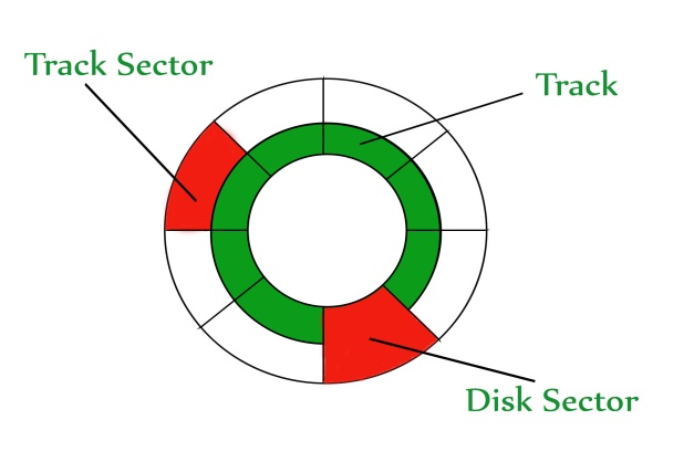
Fig 10 - Hard disk is a memory storage device
The disk is divided into tracks. Each track is further divided into sectors. The point to be noted here is that outer tracks are bigger than the inner tracks but they contain the same number of sectors and have equal storage capacity. This is because the storage density is high in sectors of the inner tracks whereas the bits are sparsely arranged in sectors of the outer tracks. Some space in every sector is used for formatting. So, the actual capacity of a sector is less than the given capacity.
Read-Write(R-W) head moves over the rotating hard disk. It is this Read-Write head that performs all the read and writes operations on the disk and hence, the position of the R-W head is a major concern. To perform a read or write operation on a memory location, we need to place the R-W head over that position. Some important terms must be noted here:
- Seek time – The time taken by the R-W head to reach the desired track from its current position.
- Rotational latency – Time is taken by the sector to come under the R-W head.
- Data transfer time – Time is taken to transfer the required amount of data. It depends upon the rotational speed.
- Controller time – The processing time taken by the controller.
- Average Access time – seek time + Average Rotational latency + data transfer time + controller time.
Note: Average Rotational latency is mostly 1/2*(Rotational latency).
In questions, if the seek time and controller time is not mentioned, take them to be zero.
If the amount of data to be transferred is not given, assume that no data is being transferred. Otherwise, calculate the time taken to transfer the given amount of data.
The average rotational latency is taken when the current position of the R-W head is not given. Because the R-W may be already present at the desired position or it might take a whole rotation to get the desired sector under the R-W head. But, if the current position of the R-W head is given then the rotational latency must be calculated.
Example –
Consider a hard disk with:
4 surfaces
64 tracks/surface
128 sectors/track
256 bytes/sector
- What is the capacity of the hard disk?
Disk capacity = surfaces * tracks/surface * sectors/track * bytes/sector
Disk capacity = 4 * 64 * 128 * 256
Disk capacity = 8 MB - The disk is rotating at 3600 RPM, what is the data transfer rate?
60 sec -> 3600 rotations
1 sec -> 60 rotations
Data transfer rate = number of rotations per second * track capacity * number of surfaces (since 1 R-W head is used for each surface)
Data transfer rate = 60 * 128 * 256 * 4
Data transfer rate = 7.5 MB/sec - The disk is rotating at 3600 RPM, what is the average access time?
Since seek time, controller time and the amount of data to be transferred is not given, we consider all the three terms as 0.
Therefore, Average Access time = Average rotational delay
Rotational latency => 60 sec -> 3600 rotations
1 sec -> 60 rotations
Rotational latency = (1/60) sec = 16.67 msec.
Average Rotational latency = (16.67)/2
= 8.33 msec.
Average Access time = 8.33 msec.
KEY TAKEAWAY
As we know, a process needs two types of time, CPU time, and IO time. For I/O, it requests the Operating system to access the disk.
However, the operating system must be fair enough to satisfy each request and at the same time, the operating system must maintain the efficiency and speed of process execution.
The technique that the operating system uses to determine the request which is to be satisfied next is called disk scheduling.
RAID
RAID refers to the redundancy array of the independent disk. It is a technology that is used to connect multiple secondary storage devices for increased performance, data redundancy, or both. It gives you the ability to survive one or more drive failures depending upon the RAID level used.
It consists of an array of disks in which multiple disks are connected to achieve different goals.
RAID technology
There are 7 levels of RAID schemes. These schemas are as RAID 0, RAID 1, ...., RAID 6.
These levels contain the following characteristics:
- It contains a set of physical disk drives.
- In this technology, the operating system views these separate disks as a single logical disk.
- In this technology, data is distributed across the physical drives of the array.
- Redundancy disk capacity is used to store parity information.
- In the case of disk failure, the parity information can be helped to recover the data.
Standard RAID levels
RAID 0
- RAID level 0 provides data striping, i.e., data can place across multiple disks. It is based on stripping that means if one disk fails then all data in the array is lost.
- This level doesn't provide fault tolerance but increases system performance.
Example:
Disk 0 | Disk 1 | Disk 2 | Disk 3 |
20 | 21 | 22 | 23 |
24 | 25 | 26 | 27 |
28 | 29 | 30 | 31 |
32 | 33 | 34 | 35 |
In this figure, blocks 0, 1, 2, 3 form a stripe.
In this level, instead of placing just one block into a disk at a time, we can work with two or more blocks placed into a disk before moving on to the next one.
Disk 0 | Disk 1 | Disk 2 | Disk 3 |
20 | 22 | 24 | 26 |
21 | 23 | 25 | 27 |
28 | 30 | 32 | 34 |
29 | 31 | 33 | 35 |
In the above figure, there is no duplication of data. Hence, a block once lost cannot be recovered.
Pros of RAID 0:
- At this level, throughput is increased because multiple data requests probably not on the same disk.
- This level fully utilizes disk space and provides high performance.
- It requires a minimum of 2 drives.
Cons of RAID 0:
- It doesn't contain any error detection mechanism.
- The RAID 0 is not a true RAID because it is not fault-tolerance.
- At this level, failure of either disk results in complete data loss in the respective array.
RAID 1
This level is called mirroring of data as it copies the data from drive 1 to drive 2. It provides 100% redundancy in case of a failure.
Example:
Disk 0 | Disk 1 | Disk 2 | Disk 3 |
A | A | B | B |
C | C | D | D |
E | E | F | F |
G | G | H | H |
Only half-space of the drive is used to store the data. The other half of the drive is just a mirror to the already stored data.
Pros of RAID 1:
- The main advantage of RAID 1 is fault tolerance. In this level, if one disk fails, then the other automatically takes over.
- At this level, the array will function even if any one of the drives fails.
Cons of RAID 1:
- At this level, one extra drive is required per drive for mirroring, so the expense is higher.
RAID 2
- RAID 2 consists of bit-level striping using hamming code parity. In this level, each data bit in a word is recorded on a separate disk, and the ECC code of data words is stored on different set disks.
- Due to its high cost and complex structure, this level is not commercially used. This same performance can be achieved by RAID 3 at a lower cost.
Pros of RAID 2:
- This level uses one designated drive to store parity.
- It uses the hamming code for error detection.
Cons of RAID 2:
- It requires an additional drive for error detection.
RAID 3
- RAID 3 consists of byte-level striping with dedicated parity. In this level, the parity information is stored for each disk section and written to a dedicated parity drive.
- In the case of a drive failure, the parity drive is accessed, and data is reconstructed from the remaining devices. Once the failed drive is replaced, the missing data can be restored on the new drive.
- At this level, data can be transferred in bulk. Thus high-speed data transmission is possible.
Disk 0 | Disk 1 | Disk 2 | Disk 3 |
A | B | C | P(A, B, C) |
D | E | F | P(D, E, F) |
G | H | I | P(G, H, I) |
J | K | L | P(J, K, L) |
Pros of RAID 3:
- At this level, data is regenerated using a parity drive.
- It contains high data transfer rates.
- At this level, data is accessed in parallel.
Cons of RAID 3:
- It required an additional drive for parity.
- It gives a slow performance for operating on small-sized files.
RAID 4
- RAID 4 consists of block-level striping with a parity disk. Instead of duplicating data, the RAID 4 adopts a parity-based approach.
- This level allows recovery of at most 1 disk failure due to the way parity works. In this level, if more than one disk fails, then there is no way to recover the data.
- Level 3 and level 4 both are required at least three disks to implement RAID.
Disk 0 | Disk 1 | Disk 2 | Disk 3 |
A | B | C | P0 |
D | E | F | P1 |
G | H | I | P2 |
J | K | L | P3 |
In this figure, we can observe one disk dedicated to parity.
At this level, parity can be calculated using an XOR function. If the data bits are 0,0,0,1 then the parity bits is XOR(0,1,0,0) = 1. If the parity bits are 0,0,1,1 then the parity bit is XOR(0,0,1,1)= 0. That means, even the number of one results in parity 0, and an odd number of one results in parity 1.
C1 | C2 | C3 | C4 | Parity |
0 | 1 | 0 | 0 | 1 |
0 | 0 | 1 | 1 | 0 |
Suppose that in the above figure, C2 is lost due to some disk failure. Then using the values of all the other columns and the parity bit, we can recompute the data bit stored in C2. This level allows us to recover lost data.
RAID 5
- RAID 5 is a slight modification of the RAID 4 system. The only difference is that in RAID 5, the parity rotates among the drives.
- It consists of block-level striping with DISTRIBUTED parity.
- Same as RAID 4, this level allows recovery of at most 1 disk failure. If more than one disk fails, then there is no way for data recovery.
Disk 0 | Disk 1 | Disk 2 | Disk 3 | Disk 4 |
0 | 1 | 2 | 3 | P0 |
5 | 6 | 7 | P1 | 4 |
10 | 11 | P2 | 8 | 9 |
15 | P3 | 12 | 13 | 14 |
P4 | 16 | 17 | 18 | 19 |
This figure shows how the parity bit rotates.
This level was introduced to make the random write performance better.
Pros of RAID 5:
- This level is cost-effective and provides high performance.
- At this level, parity is distributed across the disks in an array.
- It is used to make the random write performance better.
Cons of RAID 5:
- At this level, disk failure recovery takes a longer time as parity has to be calculated from all available drives.
- This level cannot survive in concurrent drive failure.
RAID 6
- This level is an extension of RAID 5. It contains block-level stripping with 2 parity bits.
- In RAID 6, you can survive 2 concurrent disk failures. Suppose you are using RAID 5, and RAID 1. When your disks fail, you need to replace the failed disk because if simultaneously another disk fails then you won't be able to recover any of the data, so in this case RAID, 6 plays its part where you can survive two concurrent disk failures before you run out of options.
Disk 1 | Disk 2 | Disk 3 | Disk 4 |
A0 | B0 | Q0 | P0 |
A1 | Q1 | P1 | D1 |
Q2 | P2 | C2 | D2 |
P3 | B3 | C3 | Q3 |
Pros of RAID 6:
- This level performs RAID 0 to strip data and RAID 1 to mirror. In this level, stripping is performed before mirroring.
- At this level, the drives required should be multiple of 2.
Cons of RAID 6:
- It is not utilized 100% disk capability as half is used for mirroring.
- It contains very limited scalability.
KEY TAKEAWAY
RAID refers to the redundancy array of the independent disk. It is a technology that is used to connect multiple secondary storage devices for increased performance, data redundancy, or both. It gives you the ability to survive one or more drive failures depending upon the RAID level used.
It consists of an array of disks in which multiple disks are connected to achieve different goals.
File concept
File
A file may be a named assortment of connected data that's recorded on secondary storage like magnetic disks, magnetic tapes, and optical disks. In general, a file may be a sequence of bits, bytes, lines, or records whose that means is outlined by the file's creator and user.
File Structure
A File Structure ought to be in step with a needed format that the software system will perceive.
• A file contains a sure outlined structure in step with its kind.
• A document may be a sequence of characters organized into lines.
• A supply file may be a sequence of procedures and functions.
• An object file may be a sequence of bytes organized into blocks that square measure intelligible by the machine.
• When a software system defines different file structures, it conjointly contains the code to support these file structures. Unix, MS-DOS support a minimum variety of file structure.
File Type
File kind refers to the power of the software system to differentiate different types of files like text files supply files and binary files etc. several operative systems support many sorts of files. Software system like MS-DOS and operating system have subsequent kinds of kinds of
Ordinary files
• These square measure the files that contain user data.
• These could have text, databases, or practicable programs.
• The user will apply varied operations on such files like add, modify, delete, or perhaps take away the complete file.
Directory files
• These files contain a list of file names and different data associated with these files.
Special files
• These files also are called device files.
• These files represent physical devices like disks, terminals, printers, networks, mechanisms, etc.
These files square measure of 2 varieties varieties
• Character special files − information is handled character by character as just in case of terminals or printers.
• Block special files − information is handled in blocks as within the case of disks and tapes.
File Access Mechanisms
File access mechanism refers to the style during which the records of a file could also be accessed. There square measure many ways to access files −
• Sequential access
• Direct/Random access
• Indexed consecutive access
Sequential access
Consecutive access is that during which the records square measure accessed in some sequence, i.e., the knowledge within the file is processed so as one record when the opposite. This access technique is that the most primitive one. Example: Compilers typically access files in this fashion.
Direct/Random access
• Random access file organization provides, accessing the records directly.
• Each record has its address on the file with the assistance of that it may be directly accessed for reading or writing.
• The records needn't be in any sequence at intervals of the file and that they needn't be in adjacent locations on the medium.
Indexed consecutive access
• This mechanism is made au fait base of consecutive access.
• An index is formed for every file that contains tips to varied blocks.
• Index is searched consecutive and its pointer is employed to access the file directly.
Space Allocation
Files square measure allotted disk areas by the software system. Operative systems deploy the following 3 main ways to allot disc space to files.
• Contiguous Allocation
• Linked Allocation
• Indexed Allocation
Contiguous Allocation
• Each file occupies a contiguous address area on the disk.
• Assigned disk address is in linear order.
• Easy to implement.
• External fragmentation may be a major issue with this kind of allocation technique.
Linked Allocation
• Each file carries an inventory of links to disk blocks.
• Directory contains link/pointer to 1st block of a file.
• No external fragmentation
• Effectively employed in consecutive access file.
• Inefficient just in case of direct access file.
Indexed Allocation
• Provides solutions to issues of contiguous and connected allocation.
• A index block is formed having all tips to files.
• Each file has its index block that stores the addresses of disc space occupied by the file.
• Directory contains the addresses of index blocks of files.
KEY TAKEAWAY
File
A file may be a named assortment of connected data that's recorded on secondary storage like magnetic disks, magnetic tapes, and optical disks. In general, a file may be a sequence of bits, bytes, lines, or records whose that means is outlined by the file's creator and user.
File organization and access mechanism
When a file is used, information is read and accessed into computer memory and there are several ways to access this information of the file. Some systems provide only one access method for files. Other systems, such as those of IBM, support many access methods, and choosing the right one for a particular application is a major design problem.
There are three ways to access a file into a computer system: Sequential-Access, Direct Access, Index sequential Method.
- Sequential Access –
It is the simplest access method. Information in the file is processed in order, one record after the other. This mode of access is by far the most common; for example, the editor and compiler usually access the file in this fashion.
Read and write make up the bulk of the operation on a file. A read operation -read next- read the next position of the file and automatically advance a file pointer, which keeps track of I/O location. Similarly, for the write write next append to the end of the file and advance to the newly written material.
Key points:
- Data is accessed one record right after another record in order.
- When we use the read command, it moves ahead pointer by one
- When we use the write command, it will allocate memory and move the pointer to the end of the file
- Such a method is reasonable for tape.
- Direct Access –
Another method is the direct access method also known as the relative access method. A filed-length logical record that allows the program to read and write records rapidly. In no particular order. The direct access is based on the disk model of a file since disk allows random access to any file block. For direct access, the file is viewed as a numbered sequence of blocks or records. Thus, we may read block 14 then block 59, and then we can write block 17. There is no restriction on the order of reading and writing for a direct access file.
A block number provided by the user to the operating system is normally a relative block number, the first relative block of the file is 0 and then 1, and so on.
3. Index sequential method –
It is the other method of accessing a file which is built on top of the sequential access method. These methods construct an index for the file. The index, like an index in the back of a book, contains the pointer to the various blocks. To find a record in the file, we first search the index, and then with the help of a pointer, we access the file directly.
Key points:
- It is built on top of Sequential access.
- It controls the pointer by using an index.
KEY TAKEAWAY
When a file is used, information is read and accessed into computer memory and there are several ways to access this information of the file. Some systems provide only one access method for files. Other systems, such as those of IBM, support many access methods, and choosing the right one for a particular application is a major design problem.
File directories
What is a directory?
The directory can be defined as the listing of the related files on the disk. The directory may store some or the entire file attributes.
To get the benefit of different file systems on the different operating systems, A hard disk can be divided into some partitions of different sizes. The partitions are also called volumes or minidisks.
Each partition must have at least one directory in which, all the files of the partition can be listed. A directory entry is maintained for each file in the directory which stores all the information related to that file.
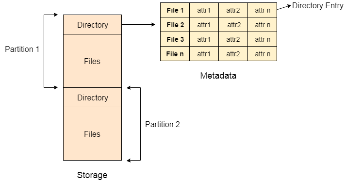
Fig 11 - Example
A directory can be viewed as a file that contains the Metadata of a bunch of files.
Every Directory supports many common operations on the file:
- File Creation
- Search for the file
- File deletion
- Renaming the file
- Traversing Files
- Listing of files
Single Level Directory
The simplest method is to have one big list of all the files on the disk. The entire system will contain only one directory which is supposed to mention all the files present in the file system. The directory contains one entry per each file present on the file system.
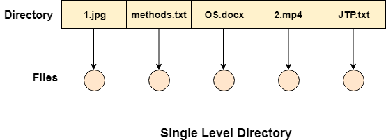
Fig 12 – Single level directory
This type of directories can be used for a simple system.
Advantages
- Implementation is very simple.
- If the sizes of the files are very small then the searching becomes faster.
- File creation, searching, deletion is very simple since we have only one directory.
Disadvantages
- We cannot have two files with the same name.
- The directory may be very big therefore searching for a file may take so much time.
- Protection cannot be implemented for multiple users.
- There are no ways to group the same kind of files.
- Choosing the unique name for every file is a bit complex and limits the number of files in the system because most of the Operating System limits the number of characters used to construct the file name.
Two Level Directory
In two-level directory systems, we can create a separate directory for each user. There is one master directory that contains separate directories dedicated to each user. For each user, there is a different directory present at the second level, containing a group of user's files. The system doesn't let a user enter the other user's directory without permission.
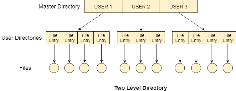
Fig 13 – Two-Level Directory
Characteristics of the two-level directory system
- Each file has a pathname as /User-name/directory-name/
- Different users can have the same file name.
- Searching becomes more efficient as only one user's list needs to be traversed.
- The same kind of files cannot be grouped into a single directory for a particular user.
Every Operating System maintains a variable as PWD which contains the present directory name (present user name) so that the searching can be done appropriately.
KEY TAKEAWAY
What is a directory?
The directory can be defined as the listing of the related files on the disk. The directory may store some or the entire file attributes.
To get the benefit of different file systems on the different operating systems, A hard disk can be divided into some partitions of different sizes. The partitions are also called volumes or minidisks.
Each partition must have at least one directory in which, all the files of the partition can be listed. A directory entry is maintained for each file in the directory which stores all the information related to that file.
File sharing
Definition - What will File Sharing mean?
File sharing is that the observation of sharing or providing access to digital info or resources, as well as documents, multimedia systems (audio/video), graphics, pc programs, pictures, and e-books. It's the non-public or public distribution of information or resources in an exceedingly network with totally different levels of sharing privileges.
File sharing is often done exploitation in many ways. The foremost common techniques for file storage, distribution, and transmission embody the following:
• Removable storage devices
• Centralized file hosting server installations on networks
• World Wide Web-oriented hyperlinked documents
• Distributed peer-to-peer networks
File Sharing
File sharing could be a utile pc service feature that evolved from removable media via network protocols, like File Transfer Protocol (FTP). Starting within the Nineties, several remote file-sharing mechanisms were introduced, as well as FTP, hotline, and net relay chat (IRC).
Operating systems conjointly offer file-sharing ways, like network file sharing (NFS). Most file-sharing tasks use 2 basic sets of network criteria, as follows:
• Peer-to-Peer (P2P) File Sharing: this can be the foremost common, however polemical, technique of file-sharing as a result of the employment of peer-to-peer computer code. Network pc users find shared information with third-party computer code. P2P file sharing permits users to directly access, transfer, and edit files. Some third-party computer code facilitates P2P sharing by aggregation and segmenting massive files into smaller items.
• File Hosting Services: This P2P file-sharing various provides a broad choice of common on-line material. These services area unit very often used with net collaboration ways, as well as email, blogs, forums, or alternative mediums, wherever direct transfer links from the file hosting services are often enclosed. These service websites sometimes host files to alter users to transfer them.
Once users transfer or create use of a file employing a file-sharing network, their pc conjointly becomes a region of that network, permitting alternative users to transfer files from the user's pc. File sharing is usually ill-gotten, except for sharing material that's not proprietary or proprietary. Another issue with file-sharing applications is that the downside of spyware or adware, as some file-sharing websites have placed spyware programs on their websites. These spyware programs area unit typically put in on users' computers while not their consent and awareness.
KEY TAKEAWAY
Definition - What will File Sharing mean?
File sharing is that the observation of sharing or providing access to digital info or resources, as well as documents, multimedia systems (audio/video), graphics, pc programs, pictures, and e-books. It's the non-public or public distribution of information or resources in an exceedingly network with totally different levels of sharing privileges.
File system implementation issues
A file is a collection of related information. The file system resides on secondary storage and provides efficient and convenient access to the disk by allowing data to be stored, located, and retrieved.
File system organized in many layers :
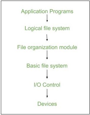
- I/O Control level –
Device drivers act as an interface between devices and Os, they help to transfer data between disk and main memory. It takes block number input and as output, it gives low-level hardware-specific instruction.
/li>
- Basic file system –
It Issues general commands to the device driver to read and write physical blocks on disk. It manages the memory buffers and caches. A block in the buffer can hold the contents of the disk block and cache stores frequently used file system metadata. - File organization Module –
It has information about files, the location of files, and their logical and physical blocks. Physical blocks do not match with logical numbers of the logical block numbered from 0 to N. It also has a free space that tracks unallocated blocks. - Logical file system –
It manages metadata information about a file i.e includes all details about a file except the actual contents of the file. It also maintains via file control blocks. File control block (FCB) has information about a file – owner, size, permissions, location of file contents.
Advantages :
- Duplication of code is minimized.
- Each file system can have its logical file system.
Disadvantages :
If we access many files at the same time then it results in low performance.
We can implement a file system by using two types of data structures :
1. On-disk Structures –
Generally, they contain information about the total number of disk blocks, free disk blocks, location of them, etc. Below given are different on-disk structures :
- Boot Control Block –
It is usually the first block of volume and it contains information needed to boot an operating system. In UNIX it is called boot block and in NTFS it is called a partition boot sector. - Volume Control Block –
It has information about a particular partition ex:- free block count, block size and block pointers, etc. In UNIX it is called superblock and in NTFS it is stored in the master file table. - Directory Structure –
They store file names and associated inode numbers. In UNIX, includes file names and associated file names and in NTFS, it is stored in the master file table. - Per-File FCB –
It contains details about files and it has a unique identifier number to allow association with the directory entry. In NTFS it is stored in the master file table.
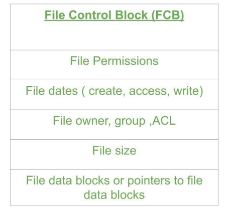
Fig 15 - FCB
2. In-Memory Structure :
They are maintained in main-memory and these are helpful for file system management for caching. Several in-memory structures given below :
5. Mount Table –
It contains information about each mounted volume.
6. Directory-Structure cache –
This cache holds the directory information of recently accessed directories.
7. System-wide open-file table –
It contains a copy of the FCB of each open file.
8. Per-process open-file table –
It contains information opened by that particular process and it maps with appropriate system-wide open-file.
Directory Implementation:
9. Linear List –
It maintains a linear list of filenames with pointers to the data blocks. It is time-consuming also. To create a new file, we must first search the directory to be sure that no existing file has the same name then we add a file at end of the directory. To delete a file, we search the directory for the named file and release the space. To reuse the directory entry either we can mark the entry as unused or we can attach it to a list of free directories.
10. Hash Table –
The hash table takes a value computed from the file name and returns a pointer to the file. It decreases the directory search time. The insertion and deletion process of files is easy. The major difficulty is hash tables are generally fixed size and hash tables are dependent on hash function on that size.
KEY TAKEAWAY
A file is a collection of related information. The file system resides on secondary storage and provides efficient and convenient access to the disk by allowing data to be stored, located, and retrieved.
File system protection and security
Protection and security need that pc resources like central processor, software, memory, etc. square measure protected. This extends to the software package besides because of the knowledge within the system. This could be done by making certain integrity, confidentiality, and availability within the software package. The system should be a shield against unauthorized access, viruses, worms, etc.
Threats to Protection and Security
A threat may be a program that's malicious and ends up in harmful effects for the system. a number of the common threats that occur in an exceedingly system square measure square measure
Virus
Viruses square measure usually little snippets of code embedded in an exceedingly system. They're dangerous and may corrupt files, destroy knowledge, crash systems, etc. they'll conjointly unfold any by replicating themselves PRN.
Trojan Horse
A malicious program will in secret access the login details of a system. Then a malicious user will use these to enter the system as a harmless being and create a disturbance.
Trap Door
A door may be a security breach that will be a gift in an exceedingly system while not the information of the users. It is exploited to hurt the info or files in an exceeding system by malicious folks.
Worm
A worm will destroy a system by victimization its resources to extreme levels. It will generate multiple copies that claim all the resources and do not permit the other processes to access them. A worm will stop working a full network during this method.
Denial of Service
These sorts of attacks don't permit legitimate users to access a system. It over-whelms the system with requests therefore it's flooded and can't work properly for different users.
Protection and Security ways
The different ways which will offer shield and security for various pc systems square measure square measure
Authentication
This deals with distinguishing every user within the system and ensuring they're World Health Organization they claim to be. The software package makes positive that each one of the user's squares measures genuine be-fore they access the system. The various ways to form positive that the users square measure authentic are:
• Username/ arcanum
Each user includes a distinct username and arcanum combination and that they have to be compelled to enter it properly before they'll access the system.
• User Key/ User Card
The users have to be compelled to punch a card into the cardboard slot or use the individual key on a computer keyboard to access the system.
• User Attribute Identification
Different user attribute identifications that may be used square measure fingerprint, eye retina, etc. The square measure distinctive for every user and the square measure is compared with the present samples within the information. The user will solely access the system if there's a match.
One Time arcanum
These passwords offer plenty of security for authentication functions. A 1-time arcanum is generated solely for a login whenever a user desires to enter the system. It can't be used quite once. The varied ways that a 1-time arcanum is enforced square measure square measure
• Random Numbers
The system will provoke numbers that correspond to alphabets that square measure pre-ar-ranged. This mixture is modified anytime a login is needed.
• Secret Key
A hardware device will produce a secret key associated with the user id for login. This key will modification anytime.
KEY TAKEAWAY
Protection and security need that pc resources like central processor, software, memory, etc. square measure protected. This extends to the software package besides because of the knowledge within the system. This could be done by making certain integrity, confidentiality, and availability within the software package. The system should be a shield against unauthorized access, viruses, worms, etc.
References:
1. Silberschatz, Galvin and Gagne, “Operating Systems Concepts”, Wiley
2. Sibsankar Halder and Alex A Aravind, “Operating Systems”, Pearson Education
3. Harvey M Dietel, “ An Introduction to Operating System”, Pearson Education
4. D M Dhamdhere, “Operating Systems: A Concept-based Approach”, 2nd Edition,
5. TMH 5. William Stallings, “Operating Systems: Internals and Design Principles ”, 6th Edition, Pearson Education