Unit - 2
Introduction to IC Engines and RAC
Terminology Used in I.C. Engines
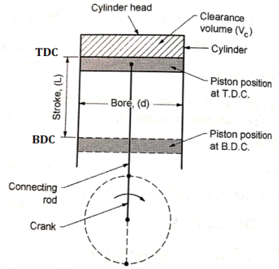
FOUR STROKE S. I. ENGINE (FOUR STROKE PETROL ENGINE)
Four stroke engine is a type of internal combustion engine which completes a power cycle with four strokes (up & down movements) of the piston during two crankshaft revolutions.
Construction of four stroke S. I. Engine (Four Stroke Petrol Engine)
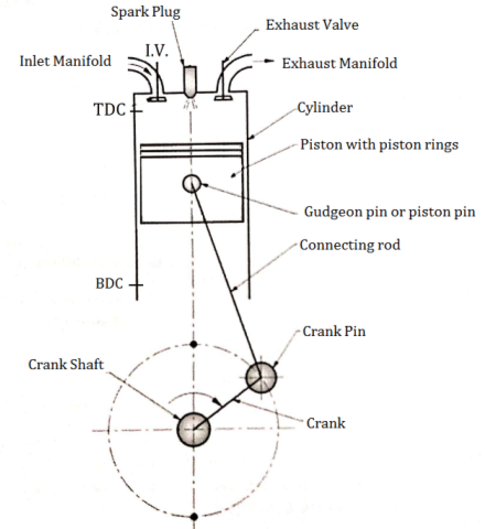
Fig: Construction of four stroke S. I. engine
An Engine consists of following important Components.
Working of four stroke S. I. Engine (Four Stroke Petrol Engine)
There are four strokes in the working of S. I. Engine which are as follows:
SUCTION STROKE OR INTAKE STROKE:
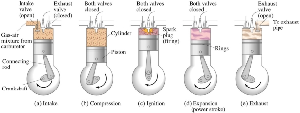
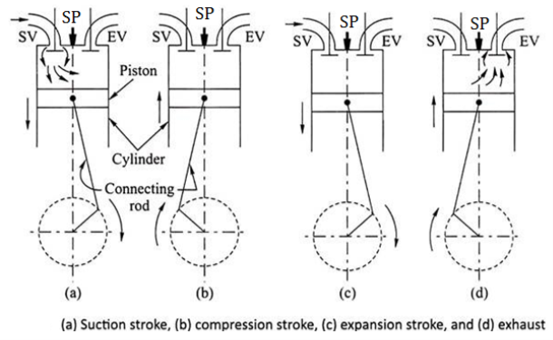
Fig: Working of four stroke S. I. engine
COMPRESSION STROKE:
WORKING OR EXPANSION STROKE OR POWER STROKE:
EXHAUST STROKE:
FOUR STROKE C. I. ENGINE (FOUR STROKE DIESEL ENGINE)
Construction of four stroke C. I. Engine (Four Stroke Diesel Engine)
Fig. below shows important components of 4 stroke Diesel engine (C.I.)
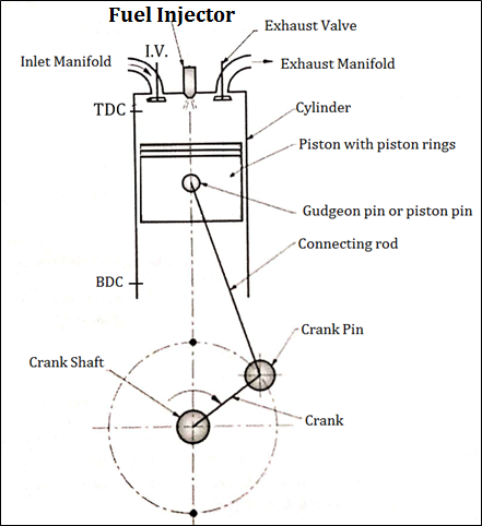
Fig: Construction of four stroke C. I. engine
An Engine consists of following important Components.
Working of four stroke C. I. Engine (Four Stroke Diesel Engine)
There are four strokes in the working of C. I. Engine which are as follows:
SUCTION STROKE OR INTAKE STROKE:
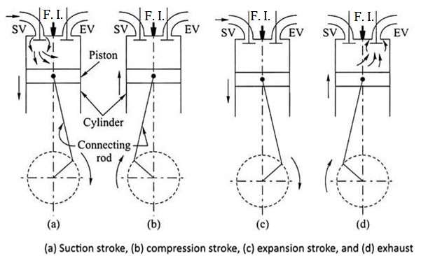
Fig: Working of four stroke C. I. engine
COMPRESSION STROKE:
WORKING OR EXPANSION STROKE OR POWER STROKE:
EXHAUST STROKE:
TWO STROKE S. I. ENGINE (TWO STROKE PETROL ENGINE)
Two stroke engine is a type of internal combustion engine which completes a power cycle with two strokes (up and down movements) of the piston during only one crankshaft revolution.
Construction of Two stroke S. I. Engine (two stroke petrol engine)
Fig. below shows important components of 2 stroke petrol engine (S.I.)
Two Stroke Engine consists of following important Components.
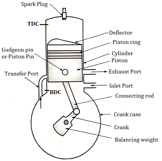
Fig: Construction of two stroke S. I. engine
Working of Two stroke S. I. Engine (two stroke petrol engine)
FIRST STROKE:
SECOND STROKE:
TWO STROKE C. I. ENGINE (TWO STROKE DIESEL ENGINE)
Construction of Two Stroke C. I. Engine (Two Stroke Diesel Engine)
Fig. below shows important components of 2 stroke diesel engine (C.I.)
Two Stroke Engine consists of following important Components.
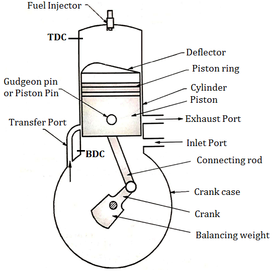
Fig: Construction of two stroke C. I. engine
Working of Two Stroke C. I. Engine (Two Stroke Diesel Engine)
FIRST STROKE:
SECOND STROKE:
Merits and Demerits
Merits
Simple design & construction: It doesn’t have valves. It simply has inlet & outlet ports which makes it simpler.
More powerful: In 2 stroke engine, every alternate stroke is power stroke unlike 4 stroked one in which power gets delivered once every 4 strokes. This gives a significant power boost. Also, the acceleration will be higher & power delivery will be uniform due to same reason.
Position doesn’t matter: 2 stroke engine can work in any position as lubrication is done through the means of fuel (as the fuel passes by through whole cylinder & crankcase).
Demerits
Less fuel efficiency: For every alternate power stroke, fuel gets consumed every alternate stroke. This makes the engine less fuel efficient although it results in uniform power delivery.
Oil addition could be expensive: Two-stroke engines require a mix of oil in with the air-fuel mixture to lubricate the crankshaft, connecting rod and cylinder walls. These oils may empty your pockets.
More pollution: 2 stroke engine produces a lot of pollution. The combustion of oil added in the mixture creates a lot of smoke which leads to air pollution.
Wastage of fuel: Sometimes the fresh charge which is going to undergo combustion gets out along with the exhaust gases. This leads to wastage of fuel & also power delivery of the engine gets effected.
Improper combustion: The exhaust gases often get trapped inside the combustion chamber. This makes the fresh charge impure. Therefore maximum power doesn’t get delivered because of improper incomplete combustion.
Figure illustrates the principle of uniflow scavenging process of OP2S gas exchange. The exhaust port opens first before ODC and a blow down discharge process commences. The discharge period up to the time of the scavenging port opening is called the free exhaust period. The intake port opens also before ODC when the cylinder pressure slightly exceeds scavenging pressure. Because the burned gas flow is toward the exhaust port, which is now having a large open area, the exhaust flow continues and few backflow occurs. When the cylinder pressure is less than the scavenging pressure, fresh air enters the cylinder and the scavenging process starts. This flow continues as long as the intake port is opened, and the scavenging total pressure exceeds the pressure in the cylinder. As the pressure rises above the exhaust pressure, the fresh charge flowing into the cylinder displaces the burned gas: a part of the fresh air mixes with the burned gas and is expelled with them. The intake port closes after the exhaust port closes; since the flow is toward the intake port continuously, additional fresh air is obtained. The additional air inflow period up to the time of intake port close is called the post intake period.
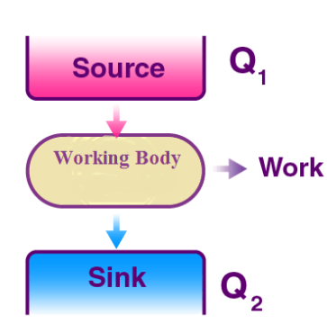
It is a well-known fact that heat flows in the direction of decreasing temperature, i.e., from a high temperature region to a low temperature region.
But the reverse process (i.e. heat transfer from low to high temperature) cannot occur by itself (Clausius Definition of Second Law). This process requires a special device called Refrigerator.
Working
In the refrigeration cycle, there are five basic components: a fluid refrigerant; a compressor, a condenser coil, an evaporator coil, and an expansion device. The compressor constricts the refrigerant vapor, raising its pressure, and pushes it into the coils on the outside of the refrigerator. When the hot gas in the coils meets the cooler air temperature of the kitchen, it becomes a liquid. Now, in the liquid form at high pressure, the refrigerant cools down as it flows into the coils inside the freezer and the fridge. The refrigerant absorbs the heat inside the fridge, cooling down the air. Lastly, the refrigerant evaporates and then flows back to the compressor, where the cycle repeats itself.
Applications
Unit of refrigeration
Rating for Refrigeration indicates the rate of removal heat. The unit of refrigeration is expressed in terms of ton of refrigeration (TR). One ton of refrigeration is defined as the amount of refrigeration effect (heat transfer rate) produced during uniform melting of one ton (100kg) of ice at 0°C to the water at the 0°C in 24 hours.
Calculation for one ton of refrigeration
Latent heat of ice is 335J/kg ( heat absorbed during melting of one kg ice0
1 ton refrigeration, 1TR = 1000 x 335 in 24 hours
= (1000 x 335) (24 x 60) in one minute
= 232.6 kJ/min
Theoretically one Ton of refrigeration taken as 232.6 kJ/min. However, in actual practice it is taken as 210kJ/min.
1 ton of refrigeration approximately equal to 3.5 kW or 12,000 BTU/h.
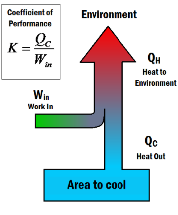
Coefficient of performance (K) is a number that describes the effectiveness of refrigerators or air conditioners, by comparing the heat that is dispelled from it to the work that had to be done to do so. It is similar to the thermal efficiency of heat engines, as they both relate what benefits you are getting to what you had to pay. The coefficient of performance is given by the equation:
K = Qc/Win
where:
A better refrigerator will require less work to remove a given amount of heat, thus having a larger coefficient of performance. From the equation, it is clear that if no work was input to the system (Win=0Win=0) the coefficient would equal infinity. This would constitute a perfect refrigerator, which is forbidden by the Second law of thermodynamics.
Maximum Coefficient of Performance
Just like there is a thermal Carnot efficiency, there is also a Carnot coefficient of performance, which describes the maximum K value for a refrigerator. This is given by the equation:

where
Natural Methods:
(a) By Using Ice or Snow:
The natural methods include the utilization of ice or snow produced naturally in cold climate. Ice melts at 0°C, so when it is placed in a space or system warmer than 0°C heat flows into ice and the space is cooled. The ice in turn melts into water by absorbing its latent heat at the rate of 335 kJ/kg. The river water, if it is quite cold, may also be used for cooling certain systems, but the removal of heat will not be as fast and satisfactory as in the case when ice or snow is used
The natural methods of refrigeration were actually used in early days. With the present developments in science and technology and the subsequent rise in the standard of leaving the refrigeration requirements have become so large that the natural methods have become inadequate and therefore obsolete.
When ice is to be used for refrigeration, winter ice can be stored by packing it in straw and dried weeds, for use in the summer months.
Mechanical Refrigeration:
Artificial or mechanical methods of producing cold have been used since 1850. Methods of mechanical refrigeration include the use of non-condensable gases and condensable gases or vapours.
When non-condensable gases are used, refrigeration can be achieved by two methods such as:
(a) Reversible or isentropic expansion of gases against the restraining force such as a piston-cylinder mechanism.
(b) Irreversible adiabatic expansion of gases from the high pressure to a low pressure through a very minute orifice or similar restriction.
Steam-Jet Refrigeration:
This system is one of the methods employed by chemical agent machines for achieving mechanical refrigeration. Evidently water is used here as refrigerant.
Steam-Jet system is primarily used in installations where chilled water is required or the systems like cold storage where the temperatures required are more than 5°C as water starts changing its volume at 4°C and starts freezing at 0°C. The principle of flash cooling is employed in achieving the objective.
There are two important components in the system, (a) steam nozzle A and (b) the flash chamber. Also, there are two distinct circuits of fluids (i) steam flow circuit, (ii) water flow circuit in the system.
(i) Steam Flow Circuit:
High pressure steam is supplied to the nozzle entrance at A. Here it takes with it any vapour flashed in the flash chamber. The vapour is entrained or sucked by the suction created by the high velocity of steam flow in the nozzle.
Here the mixture expands in the converging portion upto the throat B. It is then compressed to a pressure say 5 cm Hg corresponding to 36°C temperature in the diverging diffuser. The compressed fluid passes on to the condenser. The condensate which consists of the flashed vapour and steam from supply source is pumped back to the boiler.
(ii) Water Flow Circuit:
The chilled water required is circulated from the flash chamber, by a pump on to the point of consumption, and the balance if any is returned back to the chamber as spray.
In the flash chamber low pressure of the order of 6 mm Hg is maintained due to the suction of vapour by steam flow at nozzle. The flash point is therefore low corresponding to saturation temperature at that pressure say 5°C.
The water is chilled due to absorption from it of the latent heat required for the evaporation of a certain fraction of water during flashing. The amount of water flashed in the chamber plus any other quantity of chilled water drawn from the chamber (say for drinking or other purposes) is made up by an equivalent amount of fresh supply through the spray.
It will be noted that for obtaining water at 5°C, with a condensing temperature say 35°C, the operating pressures are 6 mm Hg and 5 mm Hg respectively, which are extremely low values. The compression ratio of approximately 8 also approaches the limit of efficiency operation. Note, if temperatures below 0°C are required, antifreeze should be added to water.
4. Refrigeration by using Liquid-Gases:
We know that a liquid can be vaporized at any desired temperature by changing its pressure. Further, heat is required to be added to the liquid during vaporization when the liquid phase changes to the gaseous phase. Accordingly, a vaporizing liquid can to produce refrigeration at any temperature. For instance, at a pressure of about 1 atm, ammonia may be made to boil at -33°C or at a pressure of about 5 atm. Freon -22 boils at 0°C.
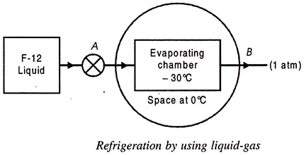
Hence in an arrangement in which a system containing some refrigerant in liquid form at a certain pressure is exposed to another system at temperature greater than refrigerating temperature.
A simple scheme of such an arrangement is shown in Fig. 36.5. Liquid Freon F-12 is supplied to the evaporating chamber through a valve at a pressure of about 1 atm. Since the boiling temperature of F-12 at this pressure is – 30°C, heat flows from the surround space at 0°C and makes the F-12 boil. Thus the space will be cooled as long as there is a supply of liquid F-12 to the evaporating chamber.
The arrangement of Fig, however, suffers from two important drawbacks:
(a) The cost of replacing Freon-12 (an expensive refrigerant) will be prohibitive as the evaporated vapour leaks out to the atmosphere.
(b) If the system were to use some other refrigerant like ammonia, it may become a hazard to life due to its discharge to atmosphere since it is a highly toxic and irritating fluid.
To eliminate these drawbacks, it will be necessary to let the refrigerant fluid work in a closed loop and be used again and again.
5. Thermo-Electric Refrigeration:
Thermoelectric effects refer to phenomenon involving the interchange of heat and electrical energy. One familiar example is the heating effect due to the flow of an electric current in a resistor. The electric power dissipation depends on the current flow I and the potential V according to the equation P = VI or P = VI = I2R. This type of energy conversion is irreversible, although some thermoelectric effects are reversible.
There are three thermoelectric effects.
They are:
(i) The See-beck effect,
(ii) Peltier effect, and
(iii) Thomson effect.
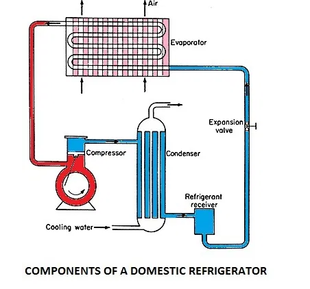
1. Evaporator: The evaporator is located in a coil form on the freezer box. The liquid refrigerant is evaporated in the evaporator by absorbing heat from the contents of the domestic refrigerator in the cabinet. The evaporator consists of copper metal rubbing surrounding the freezing and cooling compartments.
2. Condenser: The condenser is located as zigzag tubes behind the refrigerator on a mesh. In the condenser, the heat from the refrigerant at a higher temperature is rejected to the atmospheric air.
3. Compressor: The compressor is located at the base at the rear end. It compresses the refrigerant vapour to a high pressure. Reciprocating compressor is used for low-capacity domestic refrigerator.
4. Expansion Valve or Throttling Valve: An expansion valve is used to reduce the temperature and pressure of the liquid refrigerant, before it passes to the evaporator. The expansion capillary is located inside the refrigerator body hear the wall. The capillary tube is small diameter tube used as an expansion device.
5. Refrigerator cabinet: The refrigerator cabinet is thermally insulated to minimize heat flow from the atmosphere into the refrigerator. The insulation is glass fiber and the external body is of stainless steel.
The refrigerator works on the vapour compression refrigeration cycle. The refrigerant vapour is first compressed in the compressor. The compressor is a special one known as the hermetic compressor. In this unit, the compressor is sealed casing along with an electrical motor to run. This sealing prevents leakage of refrigerant and lubrication oil. The pressure and temperature of the refrigerant increases after compression and is subsequently condensed in a condenser. In the condenser, the refrigerant rejects heat to a coolant and cools down and finally gets condensed.
The condensate is then allowed to pass through capillary to reduce temperature and pressure by expansion of refrigerant. The refrigerant is filtered before entering the capillary tube. The pressure of the refrigerant, when it leaves the capillary, is maintained above atmospheric and temperature corresponds to saturation temperature so that the refrigerant can absorb heat in the evaporator. The refrigerant enters the evaporator and is heated by the heat absorbed from the body or space thereby producing the refrigeration effect. The vapour refrigerant enters the compressor again and the cycle is completed.
When power to the compressor is switched on, a humming sound is heard and the refrigerator is functional. The refrigerant flows through its circuit and ice is produced in the freezer. Frost, i.e., moisture from ambient air, gets deposited on the evaporator coil. Defrosting removes this frost. The water from defrosting is collected in a tray to be removed manually. Articles to be refrigerated are placed on shelves. Fruits and vegetables, which contain moisture, are stored at the base. The temperature here is around 8°C. Thus there are temperature gradients in the refrigerator, negative temperature in the freezer and positive temperature at the base.
Heat Pump
A heat pump is basically a heat engine run in the reverse direction. In other words, a heat pump is a device that is used to transfer heat energy to a thermal reservoir. They are often used to transfer thermal energy by absorbing heat from a cold space and releasing it to a warmer one.
Heat pumps transfer heat from cold body to a hot body by the expense of mechanical energy supplied to it by an external agent. The cold body is cooled more and more. A heat pump generally comprises four key components which include a condenser, a compressor, an expansion valve and an evaporator. The working substance used in these components is called refrigerant.
Some of the most common examples of a heat pump include freezers and air conditioners, or other heating, ventilating devices. As for the applications, heat pumps are used either for heating or cooling.
How to find the Coefficient of Performance of a Heat Pump
When we talk about heat pump efficiencies, we basically have to deal with a few key terms such as;
The performance of the heat pump is expressed by the coefficient of performance (K).
K = Heat extracted from the cold body / Work needed to transfer it to the hot body
K = Heat extracted by work done
K = QL / W
From 1st law of thermodynamics for the cyclic process ΔU = 0
ΔQ = ΔW
W = QH – QL
K = QL / QH – QL
An air- conditioned room that stands on a well- ventilated basement measures 3m high and 6m deep. One of the two 3m walls faces west and contains a double- glazed glass window of size 1.5 m by 1.5m mounted flush with the wall no external shading. There are no heat gains through the walls other than the one facing west. Calculate the sensible, latent and total heat gains on the room, room sensible heat factor from the following information. What is the required cooling capacity?
Inside conditions : 25 oC dry bulb, 50 percent RH
Outside conditions : 43 o C bulb 24 o C wet bulb
U value for wall : 1.78 W/m2 K
U value for roof : 1.316 W/m2.K
U value for floor : 1.2 W/m2.K
Effective temp difference : 25 o C
Effective temp difference : 30 o C
U value for glass : 3.12 W/m 2 K
Solar Heat gain (SHG) of glass : 300 W/m2
Internal Shading coefficient (SC) of glass: 0.86
Occupancy : 4(90W sensible heat/person)
Lightning load : 33 W/m2 of floor area.
Appliance load : 600 W (sensible) + 300W( latent)
Infiltration : 0.5 Air changes per hour
Barometric pressure : 101kPa
Ans for psychometric chart
For the inside conditions of 25oC dry bulb 50 percent RH:
Wi = 9,9167 x 10 -3 kgw/kgda
For the outside conditions of 43oC dry bulb 24oC wet bulb:
Wo = 0.0107 kgw/kgda, density of dry air = 1.095 kg/ m3
External loads:
Heat transfer rate through the walls : Since only west wall measuring 3m x 3m with a glass windows of 1.5m x 1.5m is exposed; the heat transfer rate through this wall is given by
Qwall = U wall Awall ETDwall = 1.78 x (9-2.25) x 25 = 300.38W
Heat transfer rate through roof:
Qroof = U roof A roof ETD roof = 1.316 x 18 x30 = 710.6 W(Sensible)
Heat transfer rate through floor: Since the room stands on a well ventilated basement we can assume the conditions in the basement to be same as that of the outside since the floor is not exposed to solar radiation the driving temperature difference for the roof is the temperature difference between outdoor and indoor hence
Qroof = U roof A roof ETD roof = 1.316 x 18 x30 = 710.6 W(Sensible)
Heat transfer through floor : Since the room stands on a well ventilated basement we can assume the conditions in the basement to be same as that of the outside since the floor is not exposed to solar radiation the driving temperature difference for the roof is the temperature difference between outdoor and indoor hence:
Qfloor = U floor A floor ETD floor = 1.2 x 18 x 18 = 388.8 W
Heat transfer rate through glass: This consists of radiative as well as conductive components. Since no information is available on the value of CLF it is taken as 1.0. Hence the total transfer rate through the glass window is given by :
Q glass = A glass[ U glass(To-Ti) + SHGFmaxSC] = 2.25 [ 3.12 x 18 + 300 x 0.86] = 706.9 W
Heat transfer due to infiltration: The infiltration rate is 0.5 ACH converting this into mass flow rate the infiltration rate in kg/s is given by:
minf = density of air x (ACH x volume of the room) / 3600 = 1.095 x (0.5 x 3 x3x6)/3600
minf = 8.2125 x 10 -3 kg/s
Sensible heat transfer rate due to infiltration Qs inf
Qs,inf = minf cpm (To-Ti) = 8.2125 x 10 -3 x 1021.6 x (43-25) = 151W(Sensible)
Latent heat transfer rate due to infiltration Qi,inf
Qi,inf = minf hfg( Wo – Wi) = = 8.2125 x 10 -3 x 2501 x 10 -3 (0.0107 – 0.0099) = 16.4W
Internal loads:
Load due to occupants: The sensible and latent load due to occupants are:
Qs,occ = no of occupants x SHG = 4 x 90 = 360 W
Ql,occ = no of occupants x LHG = 4 x 40 = 160 W
Load due to lightning: Assuming a CLF value of 1.0 the load due to lightnings is
Q lights = 33 x floor area = 33 x18 = 594 W
Load due to appliance:
Qs,app = 600W
Ql,app = 300W
Total sensible and latent heat are obtained by summing up all the latent load components as:
Qs,total = 300.38 + 388.8 + 706.9 + 151+360 +594+ 600 = 3811.68 W
Qi,total = 16.4 + 160+300 = 476.4 W
Total load on the building is
Qtotal = Qs,total + Ql,total = 3811.68 + 476.4 = 4288.08W
Room sensible heat factor is given by:
RSHF = Qs,total/Qtotal = 3811.68/4288.08= 0.889
To calculate the required cooling capacity one has to know the losses in return air ducts. Ventilation may be neglected as the infiltration can take care of the small ventilation requirement. Hence using a safety factor of 1.25 the required cooling
Capacity is:
Required cooling capacity = 4288.08 x 1.25 = 5360.1 W = 1.5TR
Definition of Air Conditioning:
Air conditioning can be defined as the treatment of indoor air in order to control certain conditions required for human comfort. The desirable conditions may be temperature, humidity, dust particle level, odor level, and air motion.
It is known that the physical properties of air can be controlled by cooling, heating, humidification, and dehumidification. These processes may be employed to maintain specific conditions desirable for comfort. Thus, simultaneous control of temperature, humidity, air motion, and cleanliness is known as air conditioning.
Requirements of Air Conditioning:
Human body releases about 100 W to 450 W/person depending on the activity of the person due to metabolism. The body temperature is maintained to be 97°C. But the body surface temperature changes according to the surrounding temperature and relative humidity. The body heat must be dissipated from body surface to the surrounding.
If the surrounding temperature is less than the body temperature, the flow of heat from body becomes quite easy and normal flow. If the surrounding temperature is low as in winter, the rate of flow of heat from the body is rapid and the person will feel cold. If the surrounding temperature is too hot, there would be no flow of heat.
In such situation, sweat glands become activated. The moisture of body gets evaporated which brings the temperature normal. If the outside temperature is hot and humid, little evaporation of moisture will occur from the body skin and so the person will feel hot and uncomfortable. The movement of air by fan helps to keep body comfortable.
When the room temperature becomes high due to heat gain, it causes human discomfort. When the room moisture becomes high, the increased humidity causes difficulties in disposing the body heat. For human comfort, the indoor temperature of 20°C and relative humidity 60% is quite good. Any air conditioning unit will be able to achieve the above requirement and maintain the conditions for comfort.
Applications of Refrigeration
The applications of refrigeration can be grouped into following four major equally important areas:
Dry Bulb Temperature - Tdb
The Dry Bulb temperature, usually referred to as "air temperature", is the air property that is most commonly used. When people refer to the temperature of the air they are normally referring to the dry bulb temperature.
The Dry Bulb Temperature refers basically to the ambient air temperature. It is called "Dry Bulb" because the air temperature is indicated by a thermometer not affected by the moisture of the air.
Dry-bulb temperature - Tdb, can be measured using a normal thermometer freely exposed to the air but shielded from radiation and moisture. The temperature is usually given in degrees Celsius (oC) or degrees Fahrenheit (oF). The SI unit is Kelvin (K). Zero Kelvin equals to -273oC.
The dry-bulb temperature is an indicator of heat content and is shown along the bottom axis of the psychrometric chart or along the left side of the Mollier diagram. Constant dry bulb temperatures appear as vertical lines in the psychrometric chart or horizontal lines in the Mollier diagram.
Wet Bulb Temperature - Twb
The Wet Bulb temperature is the adiabatic saturation temperature.
Wet Bulb temperature can be measured by using a thermometer with the bulb wrapped in wet muslin. The adiabatic evaporation of water from the thermometer bulb and the cooling effect is indicated by a "wet bulb temperature" lower than the "dry bulb temperature" in the air.
The rate of evaporation from the wet bandage on the bulb, and the temperature difference between the dry bulb and wet bulb, depends on the humidity of the air. The evaporation from the wet muslin is reduced when air contains more water vapor.
The Wet Bulb temperature is always between the Dry Bulb temperature and the Dew Point. For the wet bulb, there is a dynamic equilibrium between heat gained because the wet bulb is cooler than the surrounding air and heat lost because of evaporation. The wet bulb temperature is the temperature of an object that can be achieved through evaporative cooling, assuming good air flow and that the ambient air temperature remains the same.
By combining the dry bulb and wet bulb temperature in a psychrometric chart or Mollier diagram the state of the humid air can be determined. Lines of constant wet bulb temperatures run diagonally from the upper left to the lower right in the Psychrometric chart.
Dew Point Temperature - Tdp
The Dew Point is the temperature where water vapor starts to condense out of the air (the temperature at which air becomes completely saturated). Above this temperature the moisture stays in the air.
If moisture condenses on a cold bottle taken from the refrigerator the dew-point temperature of the air is above the temperature in the refrigerator.
The Dew Point temperature is always lower than the Dry Bulb temperature and will be identical with 100% relative humidity (the air is at the saturation line). As air temperature changes the Dew Point tends to remain constant unless water is added or removed from the air.
The Dew Point temperature can be measured by filling a metal can with water and some ice cubes. Stir by a thermometer and watch the outside of the can. When the vapor in the air starts to condensate on the outside of the can, the temperature on the thermometer is pretty close to the dew point of the actual air.
The Dew Point is given by the saturation line in the psychrometric chart.
Dew Point Temperature Charts
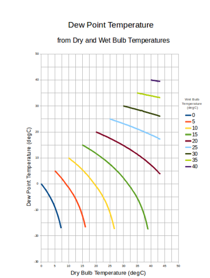
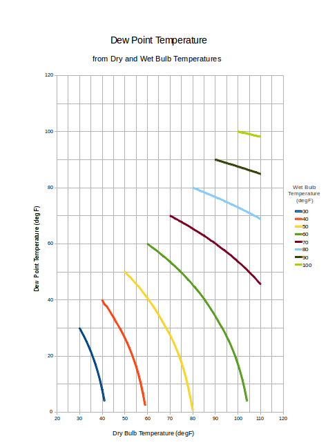
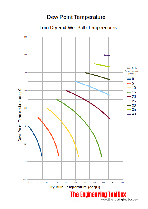
Dew point temperatures from dry and wet bulb temperatures are indicated in the charts below.
Dew Point Temperature Charts
Dew Point Temperature Chart - SI units
Dew Point Temperature Chart - Imperial units
The human body feels comfortable within certain range of temperature, relative humidity and velocity of air inside the room, these are called comfort conditions or comfort zone. The values of the parameters within comfort zone depend upon a number of factors. These are:
What is a window air conditioner?
A window air conditioner is the simplest type of AC unit. It’s a single unit with all of the parts and components contained inside one box or casing. This type of AC is usually mounted or installed in a window and plugs into a traditional electrical outlet. It’s convenient because it can be moved from window to window as needed and operates independently from a home HVAC system.
Step 1
Once you turn on the air conditioner, it draws air from inside the room using its built-in fan. This air is drawn in through the air inlet grille and is passed through a filter to remove airborne particles.
Step 2
Apart from sucking air, the air conditioner, on turning on, initiates the refrigeration process within itself. This process involves the refrigerant first taking on and then releasing heat.
As the refrigerant does that, it is first converted from a hot liquid to a gas and back to a cold liquid. The temperature of the final liquid is extremely low as compared to the temperature of the refrigerant that previously law dormant.
Step 3
In the extension of the refrigeration cycle, the cold refrigerant starts flowing through the air conditioner’s indoor coil. As the refrigerant is flowing through the coils, the hot air that the ac sucked in the first step is passed over the coils.
This coming together of the hot air and the cold refrigerant results in the decrease in the temperature of the air and the rise in the temperature of the refrigerant.
Step 4
Once the refrigerant’s temperature rises, it is converted into vapor. This vapor is then pushed through a compressor which raises its pressure and nudges it towards the condenser coil.
As it enters the condenser coil, the vapor undergoes the process of condensation, loses its heat that is expelled outside, and gets converted into a liquid. So completes the refrigeration cycle initiated in step number two.
Step 5
In this step, the cold refrigerant is passed through the expansion valve. This valve operates on the principle of throttling – a process which decreases the pressure of a high-speed liquid by passing it through an extremely narrow pathway before emitting it into a relatively open space.
As that process takes place, the temperature of the liquid further drops. This liquid then returns to the evaporator coil where it comes in contact with the air that is about to be released into the room.
Step 6
As the moderately hot air comes into contact with the extremely cold liquid, its temperature naturally nosedives. This air is then pushed past the cold coil and emitted back into your room to bring down the temperature of your indoors.
References:
1. Basic Mechanical Engineering, G Shanmugam, S Ravindran, McGraw Hill
2. Basic Mechanical Engineering, M P Poonia and S C Sharma, Khanna Publishers
3. Mechatronics: Principles, Concepts and Applications, Nitaigour Mahalik, McGraw Hill
4. Mechatronics, As per AICTE: Integrated Mechanical Electronic Systems, K.P. Ramachandran, G.K. Vijayaraghavan, M.S. Balasundaram, Wiley India
5. Mechanical Measurements & Control, Dr. D. S. Kumar. Metropolitan Book Company