Unit - 1
Introduction to Networks and Data Communications
The main objective of data communication and networking is to enable seamless exchange of data between any two points in the world. This exchange of data takes place over a computer network.
Data refers to the raw facts that are collected while information refers to processed data that enables us to take decisions. Ex. When result of a particular test is declared it contains data of all students, when you find the marks you have scored you have the information that lets you know whether you have passed or failed. The word data refers to any information which is presented in a form that is agreed and accepted upon by is creators and users.
DATA COMMUNICATION
Data Communication is a process of exchanging data or information. In case of computer networks this exchange is done between two devices over a transmission medium. This process involves a communication system which is made up of hardware and software. The hardware part involves the sender and receiver devices and the intermediate devices through which the data passes. The software part involves certain rules which specify what is to be communicated, how it is to be communicated and when. It is also called as a Protocol. The following sections describes the fundamental characteristics that are important for the effective working of data communication process and is followed by the components that make up a data communications system.
Characteristics of Data Communication The effectiveness of any data communications system depends upon the following four fundamental characteristics:
1. Delivery: The data should be delivered to the correct destination and correct user.
2. Accuracy: The communication system should deliver the data accurately, without introducing any errors. The data may get corrupted during transmission affecting the accuracy of the delivered data.
3. Timeliness: Audio and Video data has to be delivered in a timely manner without any delay; such a data delivery is called real time transmission of data.
4. Jitter: It is the variation in the packet arrival time. Uneven Jitter may affect the timeliness of data being transmitted.
Components of Data Communication: A Data Communication system has five components as shown in the diagram below:
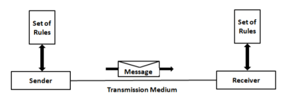
Fig.1 Components of a Data Communication System
1. Message: Message is the information to be communicated by the sender to the receiver.
2. Sender The sender is any device that is capable of sending the data (message).
3. Receiver The receiver is a device that the sender wants to communicate the data (message).
4. Transmission Medium It is the path by which the message travels from sender to receiver. It can be wired or wireless and many subtypes in both.
5. Protocol It is an agreed upon set or rules used by the sender and receiver to communicate data. A protocol is a set of rules that governs data communication. A Protocol is a necessity in data communications without which the communicating entities are like two persons trying to talk to each other in a different language without know the other language.
DATA REPRESENTATION Data is collection of raw facts which is processed to deduce information. There may be different forms in which data may be represented. Some of the forms of data used in communications are as follows:
1. Text Text includes combination of alphabets in small case as well as upper case. It is stored as a pattern of bits. Prevalent encoding system : ASCII, Unicode
2. Numbers Numbers include combination of digits from 0 to 9. It is stored as a pattern of bits. Prevalent encoding system : ASCII, Unicode
3. Images ―An image is worth a thousand words‖ is a very famous saying. In computers images are digitally stored. A Pixel is the smallest element of an image. To put it in simple terms, a picture or image is a matrix of pixel elements. The pixels are represented in the form of bits. Depending upon the type of image (black n white or color) each pixel would require different number of bits to represent the value of a pixel. The size of an image depends upon the number of pixels (also called resolution) and the bit pattern used to indicate the value of each pixel.
Example: if an image is purely black and white (two color) each pixel can be represented by a value either 0 or 1, so an image made up of 10 x 10pixel elements would require only 100 bits in memory to be stored. On the other hand, an image that includes gray may require 2 bits to represent every pixel value (00 - black, 01 – dark gray, 10 – light gray, 11 –white). So, the same 10 x 10pixel image would now require 200 bits of memory to be stored
Commonly used Image formats: jpg, png, bmp, etc
4. Audio Data can also be in the form of sound which can be recorded and broadcasted. Example: What we hear on the radio is a source of data or information. Audio data is continuous, not discrete.
5. Video refers to broadcasting of data in form of picture or movie.
DATA FLOW The devices communicate with each other by sending and receiving data. The data can flow between the two devices in the following ways.
1. Simplex
2. Half Duplex
3. Full Duplex
Simplex
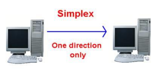
Figure 2 Simplex mode of communication
In Simplex, communication is unidirectional Only one of the devices sends the data and the other one only receives the data. Example: in the above diagram: a cpu send data while a monitor only receives data.
Half Duplex
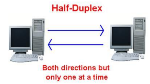
Figure 3 Half Duplex Mode of Communication
In half duplex both the stations can transmit as well as receive but not at the same time. When one device is sending other can only receive and vice-versa (as shown in figure above.) Example: A walkie-talkie.
Full Duplex
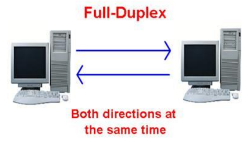
Figure 4 Full Duplex Mode of Communication
In Full duplex mode, both stations can transmit and receive at the same time. Example: mobile phones
COMPUTER NETWORK
Computer Networks are used for data communications Definition: A computer network can be defined as a collection of nodes. A node can be any device capable of transmitting or receiving data. The communicating nodes have to be connected by communication links. A Compute network should ensure reliability of the data communication process, should c security of the data performance by achieving higher throughput and smaller delay times
Categories of Network
Networks are categorized on the basis of their size. The three basic categories of computer networks are:
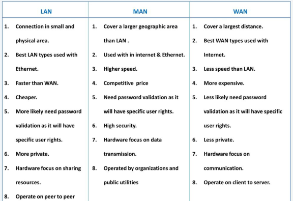
A. Local Area Networks (LAN) is usually limited to a few kilometers of area. It may be privately owned and could be a network inside an office on one of the floor of a building or a LAN could be a network consisting of the computers in a entire building.
B. Wide Area Network (WAN) is made of all the networks in a (geographically) large area. The network in the entire state of Maharashtra could be a WAN
C. Metropolitan Area Network (MAN) is of size between LAN & WAN. It is larger than LAN but smaller than WAN. It may comprise the entire network in a city like Mumbai.
STANDARDS IN NETWORKING
Standards are necessary in networking to ensure interconnectivity and interoperability between various networking hardware and software components. Without standards we would have proprietary products creating isolated islands of users which cannot interconnect.
Concept of Standard Standards provide guidelines to product manufacturers and vendors to ensure national and international interconnectivity.
Data communications standards are classified into two categories:
1. De facto Standard
- These are the standards that have been traditionally used and mean by fact or by convention.
- These standards are not approved by any organized body but are adopted by widespread use.
2. De jure standard
- It means by law or by regulation.
- These standards are legislated and approved by anybody that is officially recognized.
Standard Organizations in field of Networking
- Standards are created by standards creation committees, forums, and government regulatory agencies.
- Examples of Standard Creation Committees:
1. International Organization for standardization (ISO)
2. International Telecommunications Union – Telecommunications Standard (ITU-T)
3. American National Standards Institute (ANSI)
4. Institute of Electrical & Electronics Engineers (IEEE) 5. Electronic Industries Associates (EIA)
Key takeaway
Network security is any activity designed to protect the usability and integrity of your network and data. It includes both hardware and software technologies. It targets a variety of threats. It stops them from entering or spreading on your network. Effective network security manages access to the network.
Types of network security-
a) Firewalls
Firewalls put up a barrier between your trusted internal network and untrusted outside networks, such as the Internet. They use a set of defined rules to allow or block traffic. A firewall can be hardware, software, or both. Cisco offers unified threat management (UTM) devices and threat-focused next-generation firewalls.
b) Email security
Email gateways are the number one threat vector for a security breach. Attackers use personal information and social engineering tactics to build sophisticated phishing campaigns to deceive recipients and send them to sites serving up malware. An email security application blocks incoming attacks and controls outbound messages to prevent the loss of sensitive data.
c) Anti-virus and anti-malware software
"Malware," short for "malicious software," includes viruses, worms, Trojans, ransomware, and spyware. Sometimes malware will infect a network but lie dormant for days or even weeks. The best antimalware programs not only scan for malware upon entry, but also continuously track files afterward to find anomalies, remove malware, and fix damage.
d) Network segmentation
Software-defined segmentation puts network traffic into different classifications and makes enforcing security policies easier. Ideally, the classifications are based on endpoint identity, not mere IP addresses. You can assign access rights based on role, location, and more so that the right level of access is given to the right people and suspicious devices are contained and remediated.
e) Access control
Not every user should have access to your network. To keep out potential attackers, you need to recognize each user and each device. Then you can enforce your security policies. You can block noncompliant endpoint devices or give them only limited access. This process is network access control (NAC).
f) Application security
Any software you use to run your business needs to be protected, whether your IT staff builds it or whether you buy it. Unfortunately, any application may contain holes, or vulnerabilities, that attackers can use to infiltrate your network. Application security encompasses the hardware, software, and processes you use to close those holes.
g) Behavioral analytics
To detect abnormal network behavior, you must know what normal behavior looks like. Behavioral analytics tools automatically discern activities that deviate from the norm. Your security team can then better identify indicators of compromise that pose a potential problem and quickly remediate threats.
h) Data loss prevention
Organizations must make sure that their staff does not send sensitive information outside the network. Data loss prevention, or DLP, technologies can stop people from uploading, forwarding, or even printing critical information in an unsafe manner.
i) Web security
A web security solution will control your staff’s web use, block web-based threats, and deny access to malicious websites. It will protect your web gateway on site or in the cloud. "Web security" also refers to the steps you take to protect your own website.
j) Wireless security
Wireless networks are not as secure as wired ones. Without stringent security measures, installing a wireless LAN can be like putting Ethernet ports everywhere, including the parking lot. To prevent an exploit from taking hold, you need products specifically designed to protect a wireless network.
k) VPN
A virtual private network encrypts the connection from an endpoint to a network, often over the Internet. Typically, a remote-access VPN uses IPsec or Secure Sockets Layer to authenticate the communication between device and network.
Computer Network Architecture is defined as the physical and logical design of the software, hardware, protocols, and media of the transmission of data. Simply we can say that how computers are organized and how tasks are allocated to the computer.
The two types of network architectures are used:
Peer-To-Peer network
Client/Server network
Peer-To-Peer network
Peer-To-Peer network is a network in which all the computers are linked together with equal privilege and responsibilities for processing the data. Peer-To-Peer network is useful for small environments, usually up to 10 computers. Peer-To-Peer network has no dedicated server. Special permissions are assigned to each computer for sharing the resources, but this can lead to a problem if the computer with the resource is down.
Advantages of Peer-To-Peer Network:
It is less costly as it does not contain any dedicated server. If one computer stops working but, other computers will not stop working. It is easy to set up and maintain as each computer manages itself.
Disadvantages of Peer-To-Peer Network:
In the case of Peer-To-Peer network, it does not contain the centralized system. Therefore, it cannot back up the data as the data is different in different locations. It has a security issue as the device is managed itself.
Client/Server Network
Client/Server network is a network model designed for the end users called clients, to access the resources such as songs, video, etc. from a central computer known as Server. The central controller is known as a server while all other computers in the network are called clients. A server performs all the major operations such as security and network management. A server is responsible for managing all the resources such as files, directories, printer, etc. All the clients communicate with each other through a server. For example, if client1 wants to send some data to client 2, then it first sends the request to the server for the permission. The server sends the response to the client 1 to initiate its communication with the client 2.
Advantages of Client/Server network:
A Client/Server network contains the centralized system. Therefore, we can back up the data easily. A Client/Server network has a dedicated server that improves the overall performance of the whole system. Security is better in Client/Server network as a single server administers the shared resources. It also increases the speed of the sharing resources.
Disadvantages of Client/Server network:
Client/Server network is expensive as it requires the server with large memory. A server has a Network Operating System (NOS) to provide the resources to the clients, but the cost of NOS is very high. It requires a dedicated network administrator to manage all the resources.
Early History
- There were some communication networks, such as telegraph and telephone networks, before 1960. These networks were suitable for constant-rate communication at that time, which means that after a connection was made between two users, the encoded message (telegraphy) or voice (telephony) could be exchanged.
- A computer network, on the other hand, should be able to handle bursty data, which means data received at variable rates at different times. The world needed to wait for the packet-switched network to be invented.
Birth of Packet-Switched Networks: The theory of packet switching for bursty traffic was first presented by Leonard Kleinrock in 1961 at MIT. At the same time, two other researchers, Paul Baran at Rand Institute and Donald Davies at National Physical Laboratory in England, published some papers about packet-switched networks.
ARPANET: In the mid-1960s, mainframe computers in research organizations were stand-alone devices. Computers from different manufacturers were unable to communicate with one another. The Advanced Research Projects Agency (ARPA) in the Department of Defense (DOD) was interested in finding a way to connect computers so that the researchers they funded could share their findings, thereby reducing costs and eliminating duplication of effort. In 1967, at an Association for Computing Machinery (ACM) meeting, ARPA presented its ideas for the Advanced Research Projects Agency Network (ARPANET), a small network of connected computers.
The idea was that each host computer (not necessarily from the same manufacturer) would be attached to a specialized computer, called an interface message processor (IMP). The IMPs, in turn, would be connected to each other. Each IMP had to be able to communicate with other IMPs as well as with its own attached host. By 1969, ARPANET was a reality. Four nodes, at the University of California at Los Angeles (UCLA), the University of California at Santa Barbara (UCSB), Stanford Research Institute (SRI), and the University of Utah, were connected via the IMPs to form a network. Software called the Network Control Protocol (NCP) provided communication between the hosts.
Birth of the Internet: In 1972, Vint Cerf and Bob Kahn, both of whom were part of the core ARPANET group, collaborated on what they called the Internetting Project. They wanted to link dissimilar networks so that a host on one network could communicate with a host on another. Cerf and Kahn devised the idea of a device called a gateway to serve as the intermediary hardware to transfer data from one network to another.
TCP/IP: Cerf and Kahn’s landmark 1973 paper outlined the protocols to achieve end-toend delivery of data. This was a new version of NCP. This paper on transmission control protocol (TCP) included concepts such as encapsulation, the datagram, and the functions of a gateway. A radical idea was the transfer of responsibility for error correction from the IMP to the host machine. This ARPA Internet now became the focus of the communication effort. Around this time, responsibility for the ARPANET was handed over to the Defense Communication Agency (DCA).
In October 1977, an internet consisting of three different networks (ARPANET, packet radio, and packet satellite) was successfully demonstrated. Communication between networks was now possible. Shortly thereafter, authorities made a decision to split TCP into two protocols: Transmission Control Protocol (TCP) and Internet Protocol (IP). IP would handle datagram routing while TCP would be responsible for higher level functions such as segmentation, reassembly, and error detection. The new combination became known as TCP/IP. In 1981, under a Defence Department contract, UC Berkeley modified the UNIX operating system to include TCP/IP. This inclusion of network software along with a popular operating system did much for the popularity of internetworking. The open (nonmanufacturer-specific) implementation of the Berkeley UNIX gave every manufacturer a working code base on which they could build their products.
In 1983, authorities abolished the original ARPANET protocols, and TCP/IP became the official protocol for the ARPANET. Those who wanted to use the Internet to access a computer on a different network had to be running TCP/IP.
MILNET: In 1983, ARPANET split into two networks: Military Network (MILNET) for military users and ARPANET for nonmilitary users.
CSNET: Another milestone in Internet history was the creation of CSNET in 1981. Computer Science Network (CSNET) was a network sponsored by the National Science Foundation (NSF). The network was conceived by universities that were ineligible to join ARPANET due to an absence of ties to the Department of Defense. CSNET was a less expensive network; there were no redundant links and the transmission rate was slower. By the mid-1980s, most U.S. Universities with computer science departments were part of CSNET. Other institutions and companies were also forming their own networks and using TCP/IP to interconnect. The term Internet, originally associated with government funded connected networks, now referred to the connected networks using TCP/IP protocols.
NSFNET: With the success of CSNET, the NSF in 1986 sponsored the National Science Foundation Network (NSFNET), a backbone that connected five supercomputer centers located throughout the United States. In 1990, ARPANET was officially retired and replaced by NSFNET. In 1995, NSFNET reverted back to its original concept of a research network.
ANSNET: In 1991, the U.S. Government decided that NSFNET was not capable of supporting the rapidly increasing Internet traffic. Three companies, IBM, Merit, and Verizon, filled the void by forming a nonprofit organization called Advanced Network & Services (ANS) to build a new, high-speed Internet backbone called Advanced Network Services Network (ANSNET).
Internet Today
Today, we witness a rapid growth both in the infrastructure and new applications. The Internet today is a set of pier networks that provide services to the whole world. What has made the Internet so popular is the invention of new applications.
- World Wide Web The 1990s saw the explosion of Internet applications due to the emergence of the World Wide Web (WWW). The Web was invented at CERN by Tim Berners-Lee. This invention has added the commercial applications to the Internet.
- Multimedia Recent developments in the multimedia applications such as voice over IP (telephony), video over IP (Skype), view sharing (YouTube), and television over IP (PPLive) has increased the number of users and the amount of time each user spends on the network.
- Peer-to-Peer Applications Peer-to-peer networking is also a new area of communication with a lot of potential.
The most notable internet is called the Internet, and is composed of thousands of interconnected networks. Figure below shows a conceptual (not geographical) view of the Internet. The figure shows the Internet as several backbones, provider networks, and customer networks.
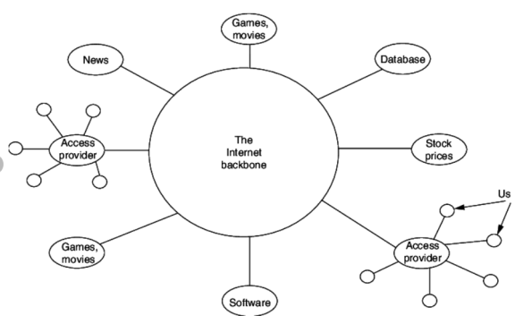
Fig 5 The Internet Today
- At the top level, the backbones are large networks owned by some communication companies such as Sprint, Verizon (MCI), AT&T, and NTT.
- The backbone networks are connected through some complex switching systems, called peering points.
- At the second level, there are smaller networks, called provider networks, that use the services of the backbones for a fee.
- The provider networks are connected to backbones and sometimes to other provider networks.
- The customer networks are networks at the edge of the Internet that actually use the services provided by the Internet. They pay fees to provider networks for receiving services.
- Backbones and provider networks are also called Internet Service Providers (ISPs).
- The backbones are often referred to as international ISPs; the provider networks are often referred to as national or regional ISPs.
Network Protocols are a set of rules governing exchange of information in an easy, reliable and secure way. Before we discuss the most common protocols used to transmit and receive data over a network, we need to understand how a network is logically organized or designed. The most popular model used to establish open communication between two systems is the Open Systems Interface (OSI) model proposed by ISO.
OSI Model
OSI model is not a network architecture because it does not specify the exact services and protocols for each layer. It simply tells what each layer should do by defining its input and output data. It is up to network architects to implement the layers according to their needs and resources available.
These are the seven layers of the OSI model −
- Physical layer −It is the first layer that physically connects the two systems that need to communicate. It transmits data in bits and manages simplex or duplex transmission by modem. It also manages Network Interface Card’s hardware interface to the network, like cabling, cable terminators, topography, voltage levels, etc.
- Data link layer − It is the firmware layer of Network Interface Card. It assembles datagrams into frames and adds start and stop flags to each frame. It also resolves problems caused by damaged, lost or duplicate frames.
- Network layer − It is concerned with routing, switching and controlling flow of information between the workstations. It also breaks down transport layer datagrams into smaller datagrams.
- Transport layer − Till the session layer, file is in its own form. Transport layer breaks it down into data frames, provides error checking at network segment level and prevents a fast host from overrunning a slower one. Transport layer isolates the upper layers from network hardware.
- Session layer − This layer is responsible for establishing a session between two workstations that want to exchange data.
- Presentation layer − This layer is concerned with correct representation of data, i.e. syntax and semantics of information. It controls file level security and is also responsible for converting data to network standards.
- Application layer − It is the topmost layer of the network that is responsible for sending application requests by the user to the lower levels. Typical applications include file transfer, E-mail, remote logon, data entry, etc.
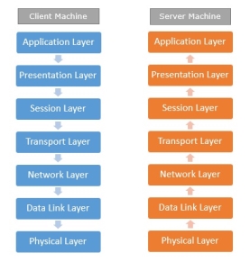
Fig 6 – Client server machine
It is not necessary for every network to have all the layers. For example, network layer is not there in broadcast networks.
When a system wants to share data with another workstation or send a request over the network, it is received by the application layer. Data then proceeds to lower layers after processing till it reaches the physical layer.
At the physical layer, the data is actually transferred and received by the physical layer of the destination workstation. There, the data proceeds to upper layers after processing till it reaches application layer.
At the application layer, data or request is shared with the workstation. So each layer has opposite functions for source and destination workstations. For example, data link layer of the source workstation adds start and stop flags to the frames but the same layer of the destination workstation will remove the start and stop flags from the frames.
Let us now see some of the protocols used by different layers to accomplish user requests.
TCP/IP
TCP/IP stands for Transmission Control Protocol/Internet Protocol. TCP/IP is a set of layered protocols used for communication over the Internet. The communication model of this suite is client-server model. A computer that sends a request is the client and a computer to which the request is sent is the server.
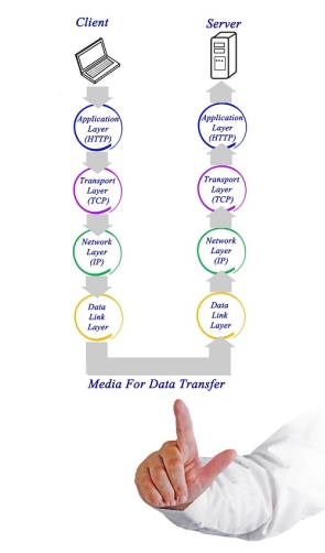
Fig 7 – Media for data transfer
TCP/IP has four layers −
- Application layer − Application layer protocols like HTTP and FTP are used.
- Transport layer − Data is transmitted in form of datagrams using the Transmission Control Protocol (TCP). TCP is responsible for breaking up data at the client side and then reassembling it on the server side.
- Network layer − Network layer connection is established using Internet Protocol (IP) at the network layer. Every machine connected to the Internet is assigned an address called IP address by the protocol to easily identify source and destination machines.
- Data link layer − Actual data transmission in bits occurs at the data link layer using the destination address provided by network layer.
TCP/IP is widely used in many communication networks other than the Internet.
FTP
As we have seen, the need for network came up primarily to facilitate sharing of files between researchers. And to this day, file transfer remains one of the most used facilities. The protocol that handles these requests is File Transfer Protocol or FTP.

Fig 8 - FTP
Using FTP to transfer files is helpful in these ways −
- Easily transfers files between two different networks
- Can resume file transfer sessions even if connection is dropped, if protocol is configure appropriately
- Enables collaboration between geographically separated teams
PPP
Point to Point Protocol or PPP is a data link layer protocol that enables transmission of TCP/IP traffic over serial connection, like telephone line.

Fig 9 - PPP
To do this, PPP defines these three things −
- A framing method to clearly define end of one frame and start of another, incorporating errors detection as well.
- Link control protocol (LCP) for bringing communication lines up, authenticating and bringing them down when no longer needed.
- Network control protocol (NCP) for each network layer protocol supported by other networks.
Using PPP, home users can avail Internet connection over telephone lines.
Key takeaways
- Network Protocols are a set of rules governing exchange of information in an easy, reliable and secure way. Before we discuss the most common protocols used to transmit and receive data over a network, we need to understand how a network is logically organized or designed. The most popular model used to establish open communication between two systems is the Open Systems Interface (OSI) model proposed by ISO.
- OSI model is not a network architecture because it does not specify the exact services and protocols for each layer. It simply tells what each layer should do by defining its input and output data. It is up to network architects to implement the layers according to their needs and resources available.
In layered architecture of Network Model, one whole network process is divided into small tasks. Each small task is then assigned to a particular layer which works dedicatedly to process the task only. Every layer does only specific work.
In layered communication system, one layer of a host deals with the task done by or to be done by its peer layer at the same level on the remote host. The task is either initiated by layer at the lowest level or at the top most level. If the task is initiated by the-top most layer, it is passed on to the layer below it for further processing. The lower layer does the same thing, it processes the task and passes on to lower layer. If the task is initiated by lower most layer, then the reverse path is taken.
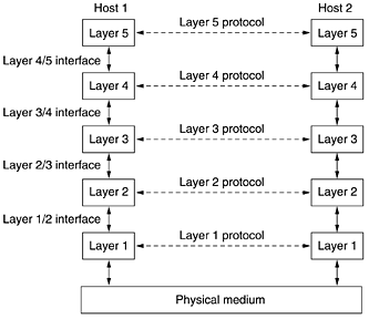
Fig 10 Layered Task
Every layer clubs together all procedures, protocols, and methods which it requires to execute its piece of task. All layers identify their counterparts by means of encapsulation header and tail.
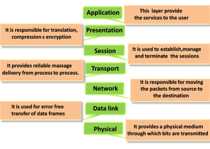
OSI stands for Open System Interconnection is a reference model that describes how information from a software application in one computer moves through a physical medium to the software application in another computer’s consists of seven layers, and each layer performs a particular network function’s model was developed by the International Organization for Standardization (ISO) in 1984, and it is now considered as an architectural model for the inter-computer communications. OSI model divides the whole task into seven smaller and manageable tasks. Each layer is assigned a particular task. Each layer is self-contained, so that task assigned to each layer can be performed independently.
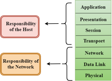
The OSI model is divided into two layers: upper layers and lower layers. The upper layer of the OSI model mainly deals with the application related issues, and they are implemented only in the software. The application layer is closest to the end user. Both the end user and the application layer interact with the software applications. An upper layer refers to the layer just above another layer. The lower layer of the OSI model deals with the data transport issues. The data link layer and the physical layer are implemented in hardware and software. The physical layer is the lowest layer of the OSI model and is closest to the physical medium. The physical layer is mainly responsible for placing the information on the physical medium.
There are the seven OSI layers. Each layer has different functions. A list of seven layers are given below:
- Physical Layer
- Data-Link Layer
- Network Layer
- Transport Layer
- Session Layer
- Presentation Layer
- Application Layer
Key Takeaways:
In present day scenario security of the system is the sole priority of any organization. The main aim of any organization is to protect their data from attackers.
TCP/IP Reference Model is a four-layered suite of communication protocols. It was developed by the DoD (Department of Defence) in the 1960s. It is named after the two main protocols that are used in the model, namely, TCP and IP. TCP stands for Transmission Control Protocol and IP stands for Internet Protocol.
The four layers in the TCP/IP protocol suite are −
Host-to- Network Layer −It is the lowest layer that is concerned with the physical transmission of data. TCP/IP does not specifically define any protocol here but supports all the standard protocols.
Internet Layer −It defines the protocols for logical transmission of data over the network. The main protocol in this layer is Internet Protocol (IP) and it is supported by the protocols ICMP, IGMP, RARP, and ARP.
Transport Layer − It is responsible for error-free end-to-end delivery of data. The protocols defined here are Transmission Control Protocol (TCP) and User Datagram Protocol (UDP).
Application Layer − This is the topmost layer and defines the interface of host programs with the transport layer services. This layer includes all high-level protocols like Telnet, DNS, HTTP, FTP, SMTP, etc.
The advantages of TCP/IP protocol suite are
- It is an industry–standard model that can be effectively deployed in practical networking problems. It is interoperable, i.e., it allows cross-platform communications among heterogeneous networks.
- It is an open protocol suite. It is not owned by any particular institute and so can be used by any individual or organization.
- It is a scalable, client-server architecture. This allows networks to be added without disrupting the current services.
- It assigns an IP address to each computer on the network, thus making each device to be identifiable over the network. It assigns each site a domain name. It provides name and address resolution services.
The disadvantages of the TCP/IP model are
- It is not generic in nature. So, it fails to represent any protocol stack other than the TCP/IP suite. For example, it cannot describe the Bluetooth connection. It does not clearly separate the concepts of services, interfaces, and protocols. So, it is not suitable to describe new technologies in new networks.
- It does not distinguish between the data link and the physical layers, which has very different functionalities. The data link layer should concern with the transmission of frames. On the other hand, the physical layer should lay down the physical characteristics of transmission. A proper model should segregate the two layers.
- It was originally designed and implemented for wide area networks. It is not optimized for small networks like LAN (local area network) and PAN (personal area network). Among its suite of protocols, TCP and IP were carefully designed and well implemented. Some of the other protocols were developed ad hoc and so proved to be unsuitable in long run. However, due to the popularity of the model, these protocols are being used even 30–40 years after their introduction.
Key takeaway
TCP/IP Reference Model is a four-layered suite of communication protocols. It was developed by the DoD (Department of Defense) in the 1960s. It is named after the two main protocols that are used in the model, namely, TCP and IP. TCP stands for Transmission Control Protocol and IP stands for Internet Protocol.
In layer 3 network addressing is one of the major tasks of Network Layer.
Network Addresses are Logical which means these are software- based addresses which are changed by appropriate configurations.
A network address always points to host / node / server or it can represent a whole network.
Network address is always configured on network interface card and is generally mapped by system with the MAC address of the machine for Layer-2 communication.
There are different kinds of network addresses that is:
- IP
- IPX
- AppleTalk
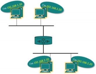
IP addressing provides a mechanism to differentiate between hosts and network. Because IP addresses are assigned in hierarchical manner the host always resides under a specific network.
The host which needs to communicate outside its subnet, needs to know destination network address where the packet/data is to be sent.
Hosts in different subnet need a mechanism to locate each other. This task is done by DNS. DNS is a server which provides Layer-3 address of remote host mapped with its domain name.
When a host acquires the Layer-3 Address (IP Address) of the remote host, it forwards all its packet to its gateway. A gateway is a router equipped with all the information which leads to route packets to the destination host.
A line code is the code used for data transmission of a digital signal over a transmission line. This process of coding is chosen so as to avoid overlap and distortion of signal such as inter-symbol interference.
Properties of Line Coding
Following are the properties of line coding −
- As the coding is done to make more bits transmit on a single signal, the bandwidth used is much reduced.
- For a given bandwidth, the power is efficiently used.
- The probability of error is much reduced.
- Error detection is done and the bipolar too has a correction capability.
- Power density is much favorable.
- The timing content is adequate.
- Long strings of 1s and 0s is avoided to maintain transparency.
Types of Line Coding
There are 3 types of Line Coding
- Unipolar
- Polar
- Bi-polar
Unipolar Signaling
Unipolar signaling is also called as On-Off Keying or simply OOK.
The presence of pulse represents a 1 and the absence of pulse represents a 0.
There are two variations in Unipolar signaling −
- Non Return to Zero NRZ
- Return to Zero RZRZ
Unipolar Non-Return to Zero NRZ
In this type of unipolar signaling, a High in data is represented by a positive pulse called as Mark, which has a duration T0 equal to the symbol bit duration. A Low in data input has no pulse.
The following figure clearly depicts this.
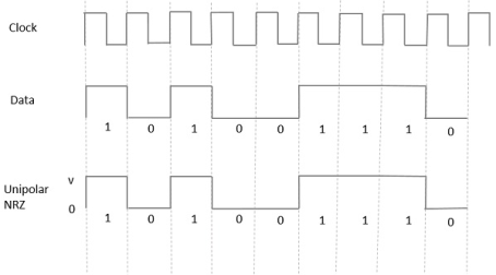
Fig 11 Uni-polar NRZ
Advantages
The advantages of Unipolar NRZ are −
- It is simple.
- A lesser bandwidth is required.
Disadvantages
The disadvantages of Unipolar NRZ are −
- No error correction done.
- Presence of low frequency components may cause the signal droop.
- No clock is present.
- Loss of synchronization is likely to occur (especially for long strings of 1s and 0s).
Unipolar Return to Zero RZRZ
In this type of unipolar signaling, a High in data, though represented by a Mark pulse, its duration T0 is less than the symbol bit duration. Half of the bit duration remains high but it immediately returns to zero and shows the absence of pulse during the remaining half of the bit duration.
It is clearly understood with the help of the following figure.
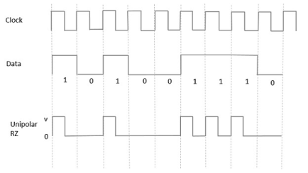
Fig 12 Unipolar RZ
Advantages
The advantages of Unipolar RZ are −
- It is simple.
- The spectral line present at the symbol rate can be used as a clock.
Disadvantages
The disadvantages of Unipolar RZ are −
- No error correction.
- Occupies twice the bandwidth as unipolar NRZ.
- The signal droop is caused at the places where signal is non-zero at 0 Hz.
Polar Signaling
There are two methods of Polar Signaling. They are −
- Polar NRZ
- Polar RZ
Polar NRZ
In this type of Polar signaling, a High in data is represented by a positive pulse, while a Low in data is represented by a negative pulse. The following figure depicts this well.
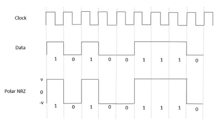
Fig 13 Polar NRZ
Advantages
The advantages of Polar NRZ are −
- It is simple.
- No low-frequency components are present.
Disadvantages
The disadvantages of Polar NRZ are −
- No error correction.
- No clock is present.
- The signal droop is caused at the places where the signal is non-zero at 0 Hz.
Polar RZ
In this type of Polar signaling, a High in data, though represented by a Mark pulse, its duration T0 is less than the symbol bit duration. Half of the bit duration remains high but it immediately returns to zero and shows the absence of pulse during the remaining half of the bit duration.
However, for a Low input, a negative pulse represents the data, and the zero level remains same for the other half of the bit duration. The following figure depicts this clearly.
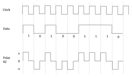
Fig 14 Polar RZ
Advantages
The advantages of Polar RZ are −
- It is simple.
- No low-frequency components are present.
Disadvantages
The disadvantages of Polar RZ are −
- No error correction.
- No clock is present.
- Occupies twice the bandwidth of Polar NRZ.
- The signal droop is caused at places where the signal is non-zero at 0 Hz.
Bipolar Signaling
This is an encoding technique which has three voltage levels namely +, - and 0. Such a signal is called as duo-binary signal.
An example of this type is Alternate Mark Inversion AMIAMI. For a 1, the voltage level gets a transition from + to – or from – to +, having alternate 1s to be of equal polarity. A 0 will have a zero voltage level.
Even in this method, we have two types.
- Bipolar NRZ
- Bipolar RZ
From the models so far discussed, we have learnt the difference between NRZ and RZ. It just goes in the same way here too. The following figure clearly depicts this.
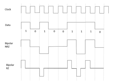
Fig 15 Bipolar RZ and Bipolar NRZ
The above figure has both the Bipolar NRZ and RZ waveforms. The pulse duration and symbol bit duration are equal in NRZ type, while the pulse duration is half of the symbol bit duration in RZ type.
Advantages
Following are the advantages −
- It is simple.
- No low-frequency components are present.
- Occupies low bandwidth than unipolar and polar NRZ schemes.
- This technique is suitable for transmission over AC coupled lines, as signal drooping doesn’t occur here.
- A single error detection capability is present in this.
Disadvantages
Following are the disadvantages −
- No clock is present.
- Long strings of data causes loss of synchronization.
Key takeaway
References:
1. Forouzan, Data Communication & Networking, McGrawhill Education
2. Lathi, B. P. & Ding, Z., (2010), Modern Digital and Analog Communication Systems, Oxford University Press
3. Stallings, W., (2010), Data and Computer Communications, Pearson.
4. Andrew S. Tanenbaum, “Computer Networks” Pearson.
5. Ajit Pal, “Data Communication and Computer Networks”, PHI
6. Dimitri Bertsekas, Robert G. Gallager, “Data Networks”, Prentice Hall, 1992