UNIT 2
Angle Modulation
Another type of modulation in continuous-wave modulation is Angle Modulation.
Angle Modulation is the process in which the frequency or the phase of the carrier signal varies according to the message signal.
The standard equation of the angle modulated wave is
s(t)=Ac cosθ i(t)-------------------(1)
Where, Ac is the amplitude of the modulated wave, which is the same as the amplitude of the carrier signal θi(t) is the angle of the modulated wave, Angle modulation is further divided into frequency modulation and phase modulation.
- Frequency Modulation is the process of varying the frequency of the carrier signal linearly with the message signal.
- Phase Modulation is the process of varying the phase of the carrier signal linearly with the message signal.
Phase Modulation
In frequency modulation, the frequency of the carrier varies whereas, in Phase Modulation (PM), the phase of the carrier signal varies in accordance with the instantaneous amplitude of the modulating signal.
So, in phase modulation, the amplitude and the frequency of the carrier signal remains constant.
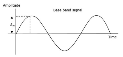
Fig.1: Baseband Signal
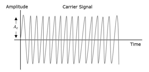
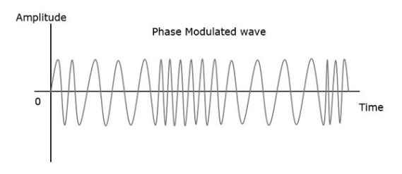
Fig.2: Phase modulated Signal
The phase of the modulated wave has infinite points, where the phase shift in a wave can take place. The instantaneous amplitude of the modulating signal changes the phase of the carrier signal. When the amplitude is positive, the phase changes in one direction and if the amplitude is negative, the phase changes in the opposite direction.
Representation
The equation for instantaneous phase ϕi in phase modulation is
ϕi=kp m(t)----------------------(1)
Where,
- Kp is the phase sensitivity
- m(t) is the message signal
The standard equation of angle modulated wave is
s(t)=Ac cos (2πfc t+ ϕi) ---------------------------------(2)
Substitute, ϕi value in the above equation.
s(t)=Ac cos (2πfc t +kp m(t)) -----------------------------------(3)
This is the equation of PM wave.
If the modulating signal,
m(t)=Am cos(2πfmt) --------------------------------(4)
Then the equation of PM wave will be
s(t)=Ac cos(2πfct+βcos(2πfmt)) -----------------------------------(5)
Where,
- β = modulation index = Δϕ=kpAm
- Δϕ is phase deviation
Phase modulation is used in mobile communication systems, while frequency modulation is used mainly for FM broadcasting.
Bessel Function and its Mathematical Analysis
Time – Domain Expression:
Since the FM wave is a nonlinear function of the modulating wave, the frequency modulation is a nonlinear process.
Let us consider a single-tone sinusoidal message signal defined by
n(t) = An cos(2nƒnt) -----------------------(1)
The instantaneous frequency is
ƒ(t) = ƒc+kƒAn cos(2nƒnt) -----------------------(2)
= ƒc+∆ƒ cos(2nƒnt) -----------------------------(3)
∆ƒ = kƒAn
 = 2 πfct + 2πKf
  m cos(2 πfmt) dt -------------------(4)
= 2 πfct + 2πKf Am / 2πfm sin(2πfmt) --------------------(5)
= 2 πfct + Kf Am/fm sin(2πfmt) ------------------------(6)
= 2 πfct + β f sin(2πfmt) ---------------------------(7)
Where β = ∆ƒ/fm = Kf Am/fm = modulation index.
Therefore, the single-tone FM wave is expressed by
FM(t) = Ac cos[2nƒct + þƒ sin(2nƒnt)] ------------------------------(8)
This is the desired time-domain expression of the single-tone FM wave
Similarly, single-tone phase modulated wave may be determined where
PM(t) = Ac cos[2nƒct + kp An cos(2nƒnt)] -------------------------(9)
Or, PM(t) = Ac cos[2nƒct +þp cos(2nƒnt)] --------------------------(10)
þp = kpAn ---------------------------(11)
The frequency deviation of the single-tone PM wave is
FM(t) = Ac cos[2 πfct + β f sin(2πfmt)]-----------------(12)
Frequency Modulation
In amplitude modulation, the amplitude of the carrier signal varies, whereas in Frequency Modulation (FM), the frequency of the carrier signal varies in accordance with the instantaneous amplitude of the modulating signal.
Hence, in frequency modulation, the amplitude and the phase of the carrier signal remains constant.
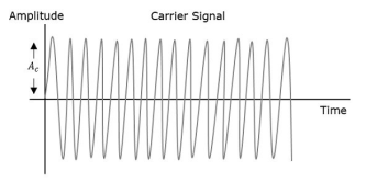
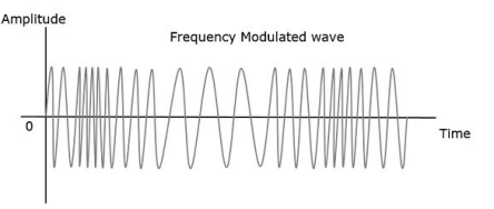
Fig.3: Frequency modulated signal
- The frequency fi of the information signal controls the rate at which the carrier frequency increases and decreases. As with AM, fi must be less than fc. The amplitude of the carrier remains constant throughout this process.
- When the information voltage reaches its maximum value then the change in frequency of the carrier will have also reached its maximum deviation above the nominal value.
- Similarly, when the information reaches a minimum the carrier will be at its lowest frequency below the nominal carrier frequency value.
- When the information signal is zero, then no deviation of the carrier will occur. The maximum change that can occur to the carrier from its base value fc is called the fc. This sets the dynamic range i.e. voltage frequency deviation, of the transmission. The dynamic range is the ratio of the largest and smallest analogue information signals that can be transmitted.
Representation:
The equation for instantaneous frequency fi in FM modulation is
Fi=fc+kfm(t)------------------------(1)
Where,
Fc is the carrier frequency
Kt is the frequency sensitivity
m(t) is the message signal
We know the relationship between angular frequency ωi and angle θi(t) as
ωi=dθi(t)/dt -------------------------(2)
2πfi=dθi(t)dt-------------------------(3)
θi(t)=2π  i dt -------------------------(4)
Substitute, fi value in the above equation.
θi(t)=2π  +k fm(t))dt-----------------(5)
θi(t)=2πfct+2πkf  (t)dt --------------------(6)
This is the equation of FM wave.
If the modulating signal is m(t)=Am cos(2πfmt) then the equation of FM wave will be
s(t)=Ac cos(2πfct+βsin(2πfmt))-------------------(1)
Where,
β = modulation index =Δf/fm=kfAm/fm----------------------(2)
The difference between FM modulated frequency which is the instantaneous frequency and normal carrier frequency is termed as Frequency Deviation. It is denoted by Δf which is equal to the product of kf and Am.
FM can be divided into Narrowband FM and Wideband FM based on the values of modulation index β.
Problem 1:
A sinusoidal modulating waveform of amplitude 5 V and a frequency of 2 KHz is applied to FM generator, which has a frequency sensitivity of 40 Hz/volt. Calculate the frequency deviation, modulation index, and bandwidth.
Solution
Given,
The amplitude of modulating signal, Am=5V
Frequency of modulating signal, fm=2KHzf
Frequency sensitivity, kf=40Hz/volt
We know the formula for Frequency deviation as
Δf=kfAm --------------------(1)
Substitute kf and Am values in the above formula.
Δf=40×5=200Hz ----------------------(2)
Therefore, frequency deviation, Δf is 200Hz
The formula for modulation index is
β=Δf fm
Substitute Δf and fm values in the above formula.
β=200 x2×1000=0.1
Here, the value of modulation index, β is 0.1, which is less than one. Hence, it is Narrow Band FM.
The formula for Bandwidth of Narrow Band FM is the same as that of AM wave.
BW=2fm
Substitute fm value in the above formula.
BW=2×2K=4KHz
Therefore, the bandwidth of Narrow Band FM wave is 4KHz.
Problem 2
An FM wave is given by s(t)=20cos(8π×106t+9sin(2π×103t)) + 9 sin(2π×103t)). Calculate the frequency deviation, bandwidth and power of FM wave.
Solution
Given, the equation of an FM wave as
s(t)=20cos(8π×106t+9sin(2π×103t))-------------------------------(1)
We know the standard equation of an FM wave as
s(t)=Ac cos(2πfct+βsin(2πfmt))---------------------------------------(2)
We will get the following values by comparing the above two equations.
Amplitude of the carrier signal, Ac=20V
Frequency of the carrier signal, fc=4×10⁶Hz
Frequency of the message signal, fm=1×10³Hz=1KHz
Modulation index, β=9
Here, the value of modulation index is greater than one. Hence, it is Wide Band FM.
We know the formula for modulation index as
β=Δf .fm
Rearrange the above equation as follows.
Δf=β/fm
Substitute β and fm values in the above equation.
Δ=9×1K=9KHz
Therefore, frequency deviation, Δf is 9KHz.
The formula for Bandwidth of Wide Band FM wave is
BW=2(β+1)fm
Substitute β and fm values in the above formula.
BW=2(9+1)1K=20KHz
Therefore, the bandwidth of Wide Band FM wave is 20KHz
Formula for power of FM wave is
Pc=Ac2 /2R
Assume, R=1ΩR=1Ω and substitute Ac value in the above equation.
P=(20)2 /2(1)=200W
Therefore, the power of FM wave is 200.
Key Takeaways:
- Frequency Modulation is the process of varying the frequency of the carrier signal linearly with the message signal.
- Phase Modulation is the process of varying the phase of the carrier signal linearly with the message signal.
A spectrum represents the relative amounts of different frequency components in any signal. It’s like the display on the graphic-equalizer in your stereo which has led showing the relative amounts of bass, midrange and treble.
These correspond directly to increasing frequencies. In technical terms, the sines and cosines form a complete set of functions, also known as a basis in the infinite-dimensional vector space of real-valued functions (gag reflex).
Given that any signal can be thought to be made up of sinusoidal signals, the spectrum then represents the "recipe card" of how to make the signal from sinusoids.
Example: 1 part of 50 Hz and 2 parts of 200 Hz. Pure sinusoids have the simplest spectrum of all, just one component:

Fig.4: Pure sinusoids
In this example, the carrier has 8 Hz and so the spectrum has a single component with value 1.0 at 8 Hz
The FM spectrum is considerably more complicated. The spectrum of a simple FM signal looks like:

Fig.5: FM spectrum
The carrier is now 65 Hz, the modulating signal is a pure 5 Hz tone, and the modulation index is 2. What we see are multiple side-bands are the spikes other than the carrier frequency separated by the modulating frequency, 5 Hz.
There are roughly 3 side-bands on either side of the carrier. The shape of the spectrum may be explained using a simple heterodyne argument: when you mix the three frequencies (fc, fm and Df) together you get the sum and difference frequencies.
The largest combination is fc + fm + Df, and the smallest is fc - fm - Df. Since Df = b fm, the frequency varies (b + 1) fm above and below the carrier.
A more realistic example is to use an audio spectrum to provide the modulation:

Fig.6: Audio spectrum
In this example, the information signal varies between 1 and 11 Hz. The carrier is at 65 Hz and the modulation index is 2. The individual side-band spikes are replaced by a more-or-less continuous spectrum. However, the extent of the side-bands is limited approximately to (b + 1) fm above and below.
Here, that would be 33 Hz above and below, making the bandwidth about 66 Hz. We see the side-bands extend from 35 to 90 Hz, so out observed bandwidth is 65 Hz.
FM Performance
Bandwidth
As we have already shown, the bandwidth of a FM signal may be predicted using:
BW = 2 (b + 1) fm
Where b is the modulation index and
fm is the maximum modulating frequency used.
The bandwidth of an FM signal has a more complicated dependency than in the AM case.
In FM, both the modulation index and the modulating frequency affect the bandwidth. As the information is made stronger, the bandwidth also grows.
Efficiency
The efficiency of a signal is the power in the side-bands as a fraction of the total. In FM signals, because of the considerable side-bands produced, the efficiency is generally high.
The side-band structure is fairly complicated, but it is safe to say that the efficiency is generally improved by making the modulation index larger .
Noise
Noise generally is spread uniformly across the spectrum (the so-called white noise, meaning wide spectrum). The amplitude of the noise varies randomly at these frequencies.
FM systems are inherently immune to random noise. In order for the noise to interfere, it would have to modulate the frequency somehow.
But the noise is distributed uniformly in frequency and varies mostly in amplitude. As a result, there is virtually no interference picked up in the FM receiver.
FM is sometimes called "static free, " referring to its superior immunity to random noise.
Key Takeaways:
- The bandwidth of a FM signal may be predicted using:
BW = 2 (b + 1) fm
- The efficiency of a signal is the power in the side-bands as a fraction of the total. In FM signals, because of the considerable side-bands produced, the efficiency is generally high.
References:
- Analog Communication by A.P Godse U.A Bakshi
- Analog Communication by Sanjay Sharma
- Analog & Digital Communication: Schaum’s Outline Series