UNIT 2
Beam and Trusses
Beam:
A beam that is just resting on the supports at the end without any connection is known as a simply supported beam. It is generally used for a vertical landing system.

2. Overhanging Beam –
A beam that is supported at the intermediate point other than ends is called an overhanging beam. Here a portion of the beam is extended beyond the support
a)

(singly overhanging beam)
b)

(doubly overhanging beam)
3. Cantilever Beam –
A beam that is fixed at one end is called a cantilever beam

Here, there are three reactions components:
b. The horizontal reaction at A (RHA)
c. The fixing moment at A (MA)
We can assume any direction for the above components.
4. Continuous Beam:
A beam having more than two support is called a continuous beam.

5. Compound Beam:
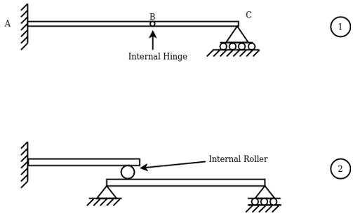
When two or more beams are joined together by using an internal hinge; or when one beam rests over another beam by using an internal roller, then such beam is called a compound beam.
A shearing force occurs when a perpendicular force is applied to static material (in this case a beam). Think of a knife cutting through a carrot. Imagine the beam is the carrot and a point load is a knife. As the knife applies a downward force, it cuts (or shears) the carrot. These forces occur along with numerous points of a beam, and it is important to determine where these shears are at the greatest points as this may be where a beam fails.
To calculate the shear forces of a beam, follow the following simple steps:
1. Start with the far left side of the beam If there is an upward force (i.e a support) then the SFD will start at this force above the x-axis. If there are a downward point load and no support, then the shear force diagram will start as a negative at the value of the point load.
Move across the beam As you come across loads, you simply add (or subtract) these loads from the value you already have, keeping a cumulative total.
It is much easier to understand when considering an example of a how-to calculates a Shear Force Diagram. So let's consider the following example to calculate the shear force diagram of a beam:
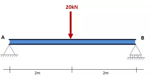
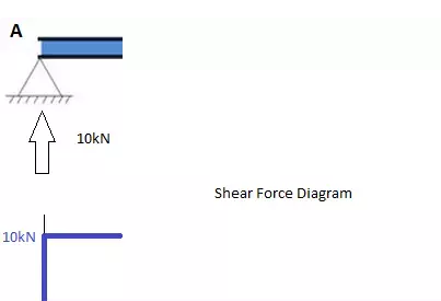
Step 1: After calculating the reactions at A and B, start the Shear Force Diagram at the first value of the force acting on the beam. In this case, it is a +10kN due to the reaction at point A:
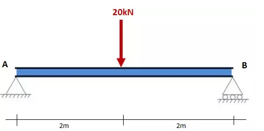
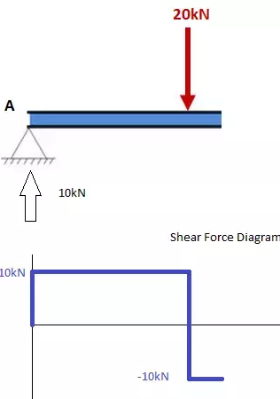
Step 2: Keep moving across the beam, stopping at every load that acts on the beam. When you get to a load, add to the Shear Force Diagram by the amount of the force. In this case, we have come to a negative 20kN force, so we will minus 20kN from the existing 10kN. i.e. 10kN - 20kN = -10kN.
Moving across the beam again, we come to another force; a positive 10kN reaction at support B. Again, add this +10kN to the shear force diagram (which is currently at -10kN) which will bring us to a shear force of 0. Since we are at the end of the beam, we will go no further and we have our final Shear Force Diagram (SFD):
Things to keep in mind:
How to Calculate the Bending Moment Diagram of a Beam
Below are simple instructions on how to calculate the bending moment diagram of a simple supported beam. Study this method as it is very versatile (and can be adapted to many different types of problem. The ability to calculate the bending moment of a beam is a very common practice for structural engineers and often comes up in college and high school exams.
Firstly, what is a Bending Moment? A moment is a rotational force that occurs when a force is applied perpendicularly to a point at a given distance away from that point. It is calculated as the perpendicular force multiplied by the distance from the point. A Bending Moment is simply the bend that occurs in a beam due to a moment. It is important to remember two things when calculating bending moments; (1) the standard units are Nm and (2) clockwise bending is taken as negative. Anyways, with the boring definitions out of the way, let's look at the steps to calculate a bending moment diagram:
1. Calculate reactions at supports and draw Free Body Diagram (FBD).
If you're not sure how to do this, click here for our tutorial. Once you have the reactions, draw your Free Body Diagram and Shear Force Diagram underneath the beam:
2. From left to right, make "cuts" before and after each reaction/load
TO calculate the bending moment of a beam, we must work in the same way we did for the Shear Force Diagram. Starting at x = 0 we will move across the beam and calculate the bending moment at each point
Cut 1
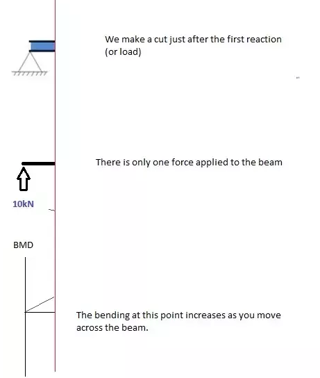
Make a "cut" just after the first reaction of the beam. In our simple example:
So, when we cut the beam, we only consider the forces that are applied to the left of our cut. In this case, we have a 10kN force in the upward direction. Now as you recall, a bending moment is simply the force x distance. So as we move further from the force, the magnitude of the bending moment will increase. We can see this in our BMD. The equation for this part of our bending moment diagram is:
-M(x) = 10(-x)
M(x) = 10x
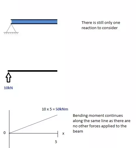
Cut 2
This cut is made just before the second force along the beam. Since there are no other loads applied between the first and second cut, the bending moment equation will remain the same. This means we can calculate the maximum bending moment (in this case at the midpoint, or x = 5) by simply substituting x=5 into the above equation:
Cut 3
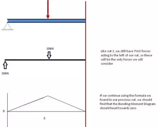
This cut is made just after the second force along the beam. Now we have TWO forces that act to the left of our cut: a 10kN support reaction and a -20kN downward acting load. So now we must consider both these forces as we progress along our beam. For every meter we move across the beam, there will a +10kNm moment added from the first force and -20kNm from the second. So after the point x=5, our Bending Moment Equation becomes
M(x) = 50 +10(x-5) - 20(x-5)
M(x) = 50 -10(x-5) for 5 ≤ x ≤ 10
NOTE: The reason we write (x-5) is because we want to know the distance from the point x=5 only. Anything before this point uses a previous equation.
Cut 4
again, let's move across to the right of our beam and make a cut just before our next force. In this case, our next cut will occur just before the reaction from Right Support. Since there are no other forces between the support and our previous cut, the equation will remain the same.
M(x) = 50 -10(x-5) for 5 ≤ x≤ 10
And let's substitute x=10 into this to find the find bending moment at the end of the beam:
M(x) = 50 - 10(10-5) = 0kNm
Variation of Shear force and bending moments:
Variation of Shear force and bending moments for various standard loads are as shown in the following Table
Type of load
SFD/BMD | Between point loads OR for the no-load region | Uniformly distributed load | Uniformly varying load |
Shear Force Diagram | Horizontal line | Inclined line | Two-degree curve (Parabola) |
Bending Moment Diagram | Inclined line | Two-degree curve (Parabola) | Three-degree curve (Cubic-parabola) |
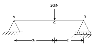
Question - Find the support reactions of a given beam for loading as shown below.
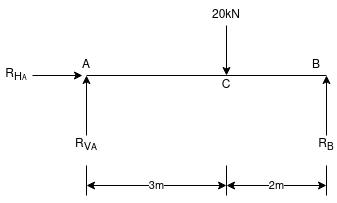
 Draw FBD of given beam & applying conditions of equilibrium
∑fx = 0
RHA = 0
∑fxy = 0
RVA – 20 + RB = 0
RVA + RB = 20 -- (1)
Taking moments at A
∑MA = 0
(20 × 3) – (RB × 5) = 0
60 – 5RB

RB = 12 kN  put in equation (1)
 RVA + 12 = 20
 RVA = 20-12 = RVA = 8 kN
Classification of statically determinate beams
Types of applied loads on the beams
Definitions
Shear force: The resultant vertical force either to the right or to the left of the section is known as shear force.
Bending moment: The algebraic sum of the moments of all forces either to the left or the right at a section in a beam is known as bending moment.
Shear force diagram: A diagram in which the ordinate represents shear force and the abscissa represents the position of the section is called a shear force diagram.
Bending moment diagram A diagram in which ordinate represents bending moment and the abscissa represents the position of the section is called the bending moment diagram.
SFD and BMD for Standard Cases
1. Cantilever subjected to:
2. Simply supported beam subjected to:
3. Overhanging beam subjected to a concentrated load at the free end.
Nature of SF and BM variation
Load S.F. B.M.
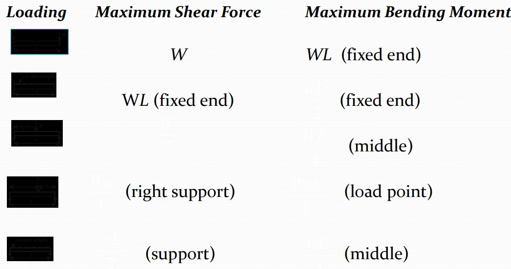
Maximum shear force and bending moment values for standard cases

Trusses:
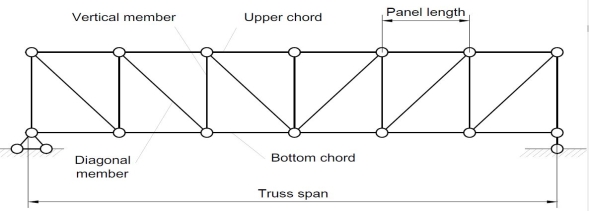
There are some basic assumptions in the designing process. It should be clarified that the construction of the trusses should conform with the design assumptions to avoid unwanted failures due to the dispersion of the forces and loads. Following are the assumptions in truss design.
Simple Truss: It is possible to create a simple truss by joining three bars together to form a triangle. We can increase the size of the truss by adding two more members with an additional joint. By repeating this process, we can develop simple trusses with different shapes as shown below. The triangular building block assures internal stability of the truss structure as it is increased in size.

Although it is possible to have non-triangular cells in a simple truss, internal stability will not be guaranteed in that case.
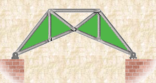
Compound Truss: A compound truss is made up of simple trusses joined together to form a larger truss. The figure below shows a compound truss consisting of two simple trusses joined by a common joint and a bar. It is also possible to have multiple simple trusses joined together to create a larger compound truss. The connection of simple trusses then becomes a design issue determined based on the size of the resulting compound truss. Compound trusses are commonly used to support loads over long spans as in bridges.
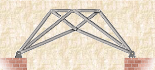
Complex Truss: A complex truss uses a general layout of members different from that used in simple and compound trusses. It often incorporates overlapping members.
1. Pratt truss

Pratt truss form for the loads in a gravity direction

Pratt truss form for the uplift loads(loads opposite to gravity)
2. Warren truss

3. North light truss

4. Vierendeel truss

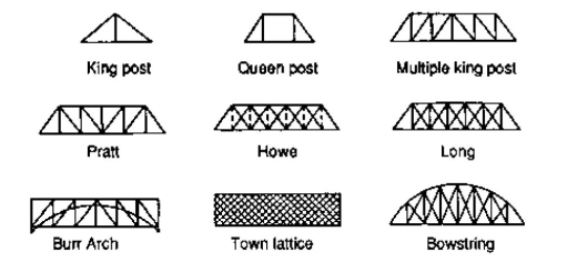
King post truss, Bowstring truss, Queen post truss, Flat truss, Lenticular truss are some other forms of trusses in the use of the industry.
Question 1) Determine the forces in all members of the truss by the joint method
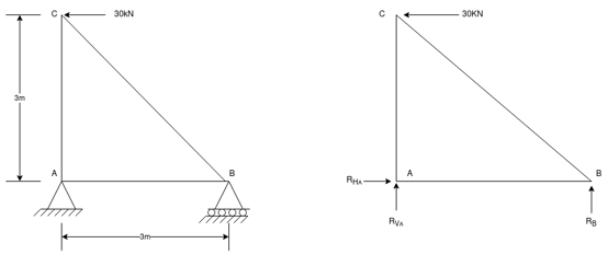
Answer 1) Consider FAB of Truss, Applying conditions of equilibrium,
 = 0
= 0
RHA + 30 Kn
 = 0
= 0
RvA + RB =0
Taking moment at point A, = 0
= 0
-(RB* 3) - (30*3) = 0
RB = -30 KN
RB =30 KN RVA = 30 KN
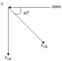
Consider Joint c, assuming forces in member AC & BC to be
Tensile, applying conditions of equilibrium,
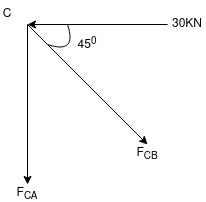
 = 0
= 0
-30 + FCB cos 45 =0
FCB =30/cos 45 = 42.42 KN (T)
-  = 0
= 0
- FcA – FCB sin 45=o
- F cA -42.42 sin 45 =0

-FCA – 30= 0
-FCA = -30 KN
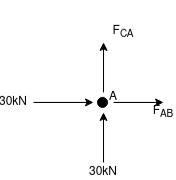
Consider Joint c, assuming forces in member AC & BC to be
Tensile, applying conditions of equilibrium,
 Fx = 0 30+FAB =0
FAB = -30KN
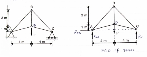
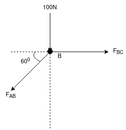
Question 2) Determine the forces in each member of the plane truss as shown in fig. in terms pf the external loading and state if the members are in tension or compression. Use 0+ 30 deg, L = 2 m and p =100N.
Diagram
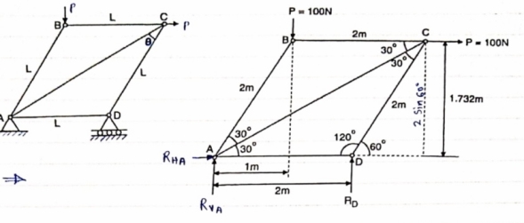
Answer 2) Consider FBD of Truss,
For equilibrium,  Fx =0
Fx =0
RHA+100 =0
RHA =-100 KN
 Fy =0 RVA = RD – 100 ….. 1
MA = 0 -------Taking moment @ A
- (Roxz) + (100*1) + (100*1.732) =0
- - 2 Rd + 100 + 1.7320 =0
- -2 Rd + 100 + 173.2 =0
- RD =136.66 N ()
From eqn (1)
RVA = 100 – 136.6
RVA= 36.6N
RVA = 36.6 N
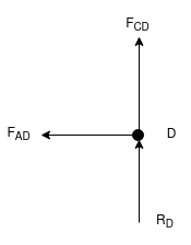
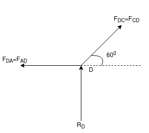
Consider Joint D, for equilibrium,
Fx =0
-FAD + FCD cos 60 =0 – (11)
Fy = 0
136.6 +FCD sin 60 +0
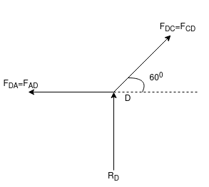
FCD = -157.73 N ©
From equation (11), Fad =- 78. 87 N (c)
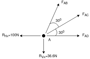
Consider point A, for the equilibrium of point A,
 Fx = 0
- 100 + FAD + FAc cos + 30 FAb cos60 = 0
-100 + (-78.87) +FAC cos 30 +FAb cos60 =0
FAc cos 30 + FAB cos60 + 178. 87 (3)
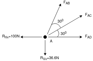
 fx =0
fx =0
-36.6 + FAC sin 30 + FAB sin 60 =0
FAC sin 30 + FAb sin 60 = 36.6
Solving equation (3) and (4)
FAC = 273.21 N (T)
FAB = -115.47 N
FAB= 115.47 N ©
Consider point B, for the equilibrium of point,
 Fx =0
Fx =0
-FAB cos60 + FBC =0
-[9-115.47) cos60]+ FBC =0
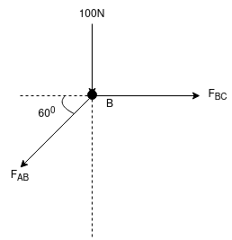
FBC = -57.73 N
FBC =57.73N
Member | AB | BC | CD | AD | AC |
force | 115.47N | 57.73N | 157.73N | 78.87N | 273.21N |
Nature | c | c | c | c | T |
Question 3) Determine the axial forces in each member of the plane truss as shown in the figure.
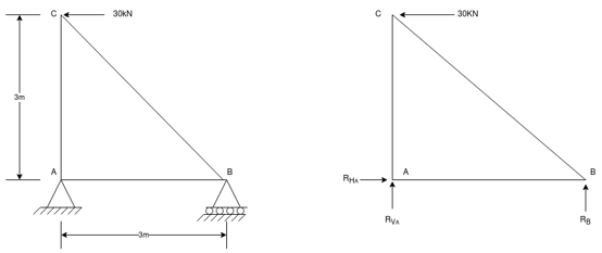
Answer 3) consider FBD of Truss,
For the equilibrium of Truss,  fx =0
fx =0
RHA + 10 =0
RHA = -10 KN
RHA =10KN (
Resolving forces vertically,
 fy =o
fy =o
RVA + RD -15 =0
RVA + RD = 15 …… (1)
Taking moment about point A,
 Fy =0
Fy =0
(10*3) – 3 Rd =0
30+ 3 Rd =0
RD= 10 KN 
RVA = 5KN ( )
)
Now Consider joint B, FBD of joint B is shown below.
Assuming forces developed in all members to be Termile,
For the equilibrium of joint we have
 fx =0
fx =0
10+FBC =0
FBC = -10 KN
FBC = 10KN (c)
 fy =0
fy =0
FAB = -15 KN
FAB = 15 KN (c)
Now consider joint c,
For the equilibrium of joint,
 fx =0
fx =0
-FBC – FAC cos 45 =0
- (-10) – FAC cos 45=0
10= FAC cos 45
FAC = 10/cos 45
FAc = 14.14 KN (T)
 fy =0
fy =0
-Fac sin 45 – FCD=0
- 14.14 sin45 = FCD
FCD = -10 KN (c)
FCD= 10 KN (c)
Consider joint D,
By observation,
FAD=0
Sr .No | Member | Force | Nature |
1 | AB | 15 KN | c |
2 | BC | 10KN | c |
3 | CD | 10KN | c |
4 | DA | 0 | - |
5 | AC | 14.14 | T |
Question 4) Member AB & BC can support a maximum compressive force of 800 N & members AD, DC, BD can support a max. Tensile. Force of 2000N Determine the greatest land p that
Answer 4) Consider following the geometry of the figure.
tan 1 = ¼
1 = ¼
 14.04
14.04
 2 =
2 =  =45
=45
Consider
 fx =0 RHA = 0
∈Fy =o RVA + Rc = p…(1)
∈ma =0
Hp- 8 Rc =0
Rc =P/2 N ( ) RvA = (P/2) N (
 )
)
Consider point A C assuming all forces as Tensile)
∈fx =0
FAD cos 14.04+FAB cos 45 =0… (2)
∈fy = 0 p/2= Fad sin 14.04 + FAB sin 45 =0….. (3)
FAB = 2743.9 N > 800 N ( Not Allowed)
Let FAD = 2000 N (T) Then from eqn (2) & (3)
FAB =-274.9 N > 800 ( Not allowed)
Let FAB = .800 N ©, Then put this eqn (2) (3) we get
FAB = 583 N < 2000 N (Allowed) From Eqn (2) P= 848.9 N
Method of joint: This method involves isolating each joint of the truss and considering the equilibrium of the joint when determining the member axial force. Two equations used in determining the member axial forces are ∑ Fx = 0 and ∑ Fy = 0. Joints are isolated consecutively for analysis based on the principle that the number of the unknown member axial forces should never be more than two in the joint under consideration in a plane trust.
Analysis of Trusses by Method of Joint
This method is based on the principle that if a structural system constitutes a body in equilibrium, then any joint in that system is also in equilibrium and, thus, can be isolated from the entire system and analyzed using the conditions of equilibrium. The method of the joint involves successively isolating each joint in a truss system and determining the axial forces in the members meeting at the joint by applying the equations of equilibrium. The detailed procedure for analysis by this method is stated below.
Procedure for Analysis
•Verify the stability and determinacy of the structure. If the truss is stable and determinate, then proceed to the next step.
•Determine the support reactions in the truss.
•Identify the zero-force members in the system. This will immeasurably reduce the computational efforts involved in the analysis.
•Select a joint to analyze. At no instance should there be more than two unknown member forces in the analyzed joint.
•Draw the isolated free-body diagram of the selected joint, and indicate the axial forces in all members meeting at the joint as tensile (i.e. as pulling away from the joint). If this initial assumption is wrong, the determined member axial force will be negative in the analysis, meaning that the member is in compression and not in tension.
•Apply the two equations Σ Fx = 0 and Σ Fy = 0 to determine the member axial forces.
•Continue the analysis by proceeding to the next joint with two or fewer unknown member forces.

Method of the section: This method entails passing an imaginary section through the truss to divide it into two sections. The member forces are determined by considering the equilibrium of the part of the truss on either side of the section. This method is advantageous when the axial forces in specific members are required in a truss with several members.

Analysis of Trusses by Method of Section
Sometimes, determining the axial force in specific members of a truss system by the method of the joint can be very involving and cumbersome, especially when the system consists of several members. In such instances, using the method of the section can be timesaving and, thus, preferable. This method involves passing an imaginary section through the truss so that it divides the system into two parts and cuts through members whose axial forces are desired. Member axial forces are then determined using the conditions of equilibrium. The detailed procedure for analysis by this method is presented below.
Procedure for Analysis of Trusses by Method of Section
•Check the stability and determinacy of the structure. If the truss is stable and determinate, then proceed to the next step.
•Determine the support reactions in the truss.
•Make an imaginary cut through the structure so that it includes the members whose axial forces are desired. The imaginary cut divides the truss into two parts.
•Apply forces to each part of the truss to keep it in equilibrium.
•Select either part of the truss for the determination of member forces.
•Apply the conditions of equilibrium to determine the member axial forces.
References:
1. Beer, F.P and Johnston Jr. E.R., “Vector Mechanics for Engineers (In SI Units): Statics and Dynamics”, 8th Edition, Tata McGraw-Hill Publishing company, New Delhi (2004).
2. Vela Murali, “Engineering Mechanics”, Oxford University Press (2010).
3. A Textbook of Engineering Mechanics, R.K. Bansal, Laxmi Publications.
4. Engineering Mechanics, R.S. Khurmi, S.Chand Publishing.
5. Meriam J.L. and Kraige L.G., “Engineering Mechanics- Statics - Volume 1, Dynamics- Volume 2”, Third Edition, John Wiley & Sons (1993).
6. Rajasekaran S and Sankarasubramanian G., “Engineering Mechanics Statics and Dynamics”, 3 rd Edition, Vikas Publishing House Pvt. Ltd., (2005).
7. Bhavikatti, S.S, and Rajashekarappa, K.G., “Engineering Mechanics”, New Age International (P) Limited Publishers, (1998).
8. Engineering mechanics by Irving H. Shames, Prentice-Hall.