Unit – 2
Vapour Compression System
It is a widely recognized reality that warmness flows with inside the course of lowering temperature, i.e., from an excessive temperature location to a low temperature location.
But the opposite method (i.e. warmness switch from low to excessive temperature) cannot arise with the aid of using itself (Classis Definition of Second Law). This method calls for a unique tool known as Refrigerator.
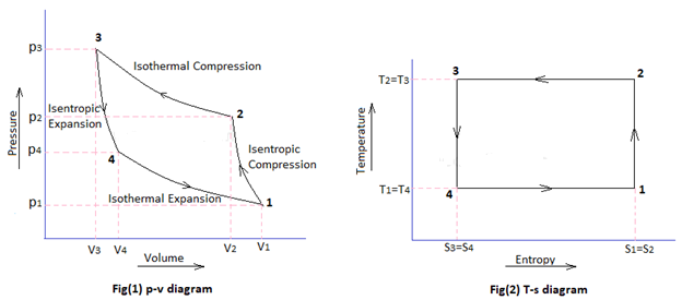
Reversed Carnot Cycle
Carnot cycle is a very reversible cycle which includes reversible isothermal strategies and isentropic strategies. It has the most performance for a given temperature limit. Since its miles a reversible cycle, all 4 strategies may be reversed. This will opposite the course of warmth and paintings interactions, therefore using refrigeration cycle.
![The Carnot Refrigerator and The Reversed Carnot Cycle [5] | Download Scientific Diagram](https://glossaread-contain.s3.ap-south-1.amazonaws.com/epub/1643261106_9023619.png)
Fig: Reversed carnot cycle
The cycle consists of
1-2: Isothermal heat transfer from cold medium to refrigerant (Evaporator)
2-3: Isentropic (Reversible adiabatic) compression
3-4: Isothermal heat rejection (condenser)
4-1: Isentropic Expansion

Practical Difficulties of Carnot cycle
Compression of two-phase mixture from 1-2
Expansion from 4-1 results in a very wet refrigerant, causing erosion of turbine blades.
Any system that can convert warmness into mechanical paintings is referred to as a warmness engine.
Carnot engine incorporates a supply, sink, running substance, and an insulating stand.
The running substance is subjected to 4 approaches with inside the shape of a cycle.
It includes approaches like isothermal expansion, adiabatic expansion, isothermal compression, and adiabatic compression.
These approaches are being performed at a totally gradual charge or quasi statically a good way to have a reversible process.
Ideally, the Carnot engine is taken to be reversible because it has the subsequent properties:
1. A flawlessly insulating frictionless piston and a cylinder with flawlessly insulating partitions are used as a running substance in order that it doesn’t have any dissipative results like friction, conduction of warmth.
2. The running substance is constantly in thermal equilibrium with the supply and sink.
3. The alternate in strain and quantity of the running substance ought to take vicinity at a gradual charge.
4. A Carnot Engine has 100 % efficiency. But, in real practice, there's friction and dissipation of warmth every time a few paintings is achieved on a system.
There isn't any such tool that acts as a great insulator or best conductor. Also, such gradual approaches are tough to hold out.
In actual engines, the warmth transfers at a surprising alternate in temperature while in a Carnot engine, the temperature stays constant.
In our daily lives, reversible approaches can’t be finished and there's no such engine with 100 % efficiency. Thus, the Carnot cycle is almost now no longer possible.
Key Takeaways:
- This method calls for a unique tool known as Refrigerator.
- This will opposite the course of warmth and paintings interactions, therefore using refrigeration cycle.
- Carnot engine incorporates a supply, sink, running substance, and an insulating stand.
- There isn't any such tool that acts as a great insulator or best conductor. Also, such gradual approaches are tough to hold out.
Reversed Carnot cycle has following limitations:
The obstacles of Carnot Cycle are as follows
The Carnot Cycle is a perfect cycle because of this that that did now no longer exist and not possible to assemble so, it's far only a theoretical concept.
The isothermal manner says that the temperature is consistent however the Carnot Cycle explains there may be warmth addition with inside the isothermal growth manner which isn't always feasible.
The Carnot Cycle is used to have a look at the warmth engine and now no longer expand to different kinds of devices.
In the realistic engine, the warmth loss may be feasible in which the Carnot Cycle it isn't always referred to which ends with inside the most efficiency (which isn't always feasible).
It cannot be utilized in real practice.
Because all reversible manner are not possible practically.
Heat addition and rejection cannot takes area at consistent temperature.
Two isothermal and adiabatic tactics are quasi static manner that's once more now no longer feasible.
Isothermal warmth addition after the saturated vapor line may be very hard to gain because it includes warmth addition on the identical time growth of steam.
Due to the above reasons, it isn't viable to gain the excessive performance as derived the Carnot vapor cycle.
The Carnot cycle is the maximum green cycle viable. It includes 4 simple reversible procedures which means that the cycle as an entire is likewise reversible.
The 4 reversible procedures are: Isothermal growth (with the aid of using setting the device in touch with a warmth reservoir with temperature T1).
Adiabatic growth to T2 < T1.
Key Takeaways:
- The Carnot Cycle is a perfect cycle because of this that that did now no longer exist and not possible to assemble so, it's far only a theoretical concept.
- Heat addition and rejection cannot takes area at consistent temperature.
- Due to the above reasons, it isn't viable to gain the excessive performance as derived the Carnot vapor cycle.
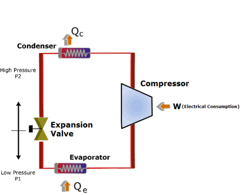
- The Vapor Compression Refrigeration Cycle includes 4 additives: compressor, condenser, growth valve/throttle valve and evaporator.
- The excessive-strain refrigerant flows via a condenser/warmness exchanger earlier than achieving the preliminary low strain and going lower back to the evaporator.
- An extra special clarification of the stairs is as defined below.
Step 1: Compression
- The refrigerant (for instance R-717) enters the compressor at low temperature and occasional strain. It is in a gaseous state. Here, compression takes location to elevate the temperature and refrigerant strain.
- Since this manner calls for work, an electric powered motor can be used. Compressors themselves may be scroll, screw, centrifugal or reciprocating types.
Step 2: Condensation
- The condenser is basically a warmness exchanger. Heat is transferred from the refrigerant to a waft of water. This water is going to a cooling tower for cooling with inside the case of water-cooled condensation. Note that seawater and air-cooling techniques may play this role. As the refrigerant flows via the condenser, it's far in a consistent strain. One cannot come up with the money for to disregard condenser protection and performance. Specifically, strain manipulate is paramount for protection and performance motives. There are numerous strain-controlling gadgets to attend to this requirement
Step 3: Throttling and Expansion
- When the refrigerant enters the throttling valve, it expands and releases strain. Consequently, the temperature drops at this level. Because of those changes, the refrigerant leaves the throttle valve as a liquid vapor mixture, normally in proportions of round 75 % and 25 % respectively.
- First, they hold a strain differential among low- and excessive-strain sides. Second, they manipulate the quantity of liquid refrigerant getting into the evaporator.
Step 4: Evaporation
- At this level of the Vapor Compression Refrigeration Cycle, the refrigerant is at a decrease temperature than its surroundings. Therefore, it evaporates and absorbs latent warmness of vaporization. Heat extraction from the refrigerant takes place at low strain and temperature. Compressor suction impact allows hold the low strain. There are one-of-a-kind evaporator variations with inside the market, however the primary classifications are liquid cooling and air cooling, relying whether or not they cool liquid or air respectively.
 ’
’
Fig: Schematic Representation of the Steps
Problems with inside the Vapor Compression Cycle
- The Coefficient of Performance (COP) expresses the performance of this cycle. Knowing that the goal of the fridge is warmness elimination and that this manner calls for work, the COP of the cycle will become: Where “h” is the enthalpy with inside the gadget.
- Some of the Vapor Compression Refrigeration Cycle Problems which can have an effect on this fee are: Compressor Leakage/Failure
- The failure of a commercial refrigeration compressor may be high priced affair to the enterprise and adverse to the manufacturer’s reputation.
- Often, producers will tear down lower back compressors in seek faults. Over years of studies, a few not unusual place motives for compressor failure were recognized to consist of lubrication problems, overheating, slugging, flood lower back and contamination.
- Fouling – Evaporator and Condenser Fouling is any insulator hinders switch among the water and the refrigerant. It should end result from algae growth, sedimentation, scale formation or slime.
- As this trouble will increase head strain, it is able to cause elevated strength use via way of means of the compressor. What is the quality practice? Keep the evaporator floor and condenser tubes clean. Water remedy practices want to be on factor to preserve this trouble at bay.
- Motor Cooling The motor is without difficulty the best strength customer with inside the vapor compression cycle. Most instances whilst performance drops on this device, it's far due to a cooling trouble. Many problems should cause this- blocked air filters, grimy air passages etc. Regular tests of the chiller logs ought to unearth any anomaly, specially the contrast among amperage and voltage.
- Liquid Line Restriction If you're a refrigeration technician and also you come across low evaporator strain, one of the regions to test is the liquid line, especially for any shape of limit.
- Many different signs should factor to the trouble that impacts the gadget enthalpy as proven via way of means of the subsequent examples: Abnormally excessive discharge temperature Low modern draw High superheats Low condensing pressures Local frost near the limit Bubbles in sight glass In business cooling, liquid line limit can degrade cooling potential of the gadget via way of means of as a whole lot as 50%.
- Diagnosis of this trouble does now no longer to be fancy, as a skilled technician can inform something isn't ok via way of means of simply checking the gadget records or checking visually.
- If you aren't familiar with the gadget, you could want to behavior some checks to pinpoint the issue. The first one is temperature drop check, that's executed in any respect factors possibly to expand limit.
- You can also carry out a freeze check if locating the precise factor will become troublesome. This check is available in reachable whilst you suspect numerous additives including evaporator, feeder tubes and metering device.
- Thermal imaging must be the maximum superior and dependable technique of figuring out liquid line limit. It offers actual time effects that assist you become aware of the trouble as proven via way of means of temperature changes.
Key Takeaways:
- The excessive-strain refrigerant flows via a condenser/warmness exchanger earlier than achieving the preliminary low strain and going lower back to the evaporator.
- It is in a gaseous state. Here, compression takes location to elevate the temperature and refrigerant strain.
- Consequently, the temperature drops at this level. Because of those changes, the refrigerant leaves the throttle valve as a liquid vapor mixture, normally in proportions of round 75 % and 25 % respectively.
- There are one-of-a-kind evaporator variations with inside the market, however the primary classifications are liquid cooling and air cooling, relying whether or not they cool liquid or air respectively.
Components of Vapour Compression system:
- Compressor
- Condenser
- Receiver
- Expansion Valve
- Evaporator
- Compressor: The low pressure & temp. Refrigerant from evaporator is drawn into the compressor through the inlet or suction valve, where it is compressed to a high pressure & temp. The high pressure & temp vapour refrigerant is discharged into the condenser through the delivery or discharge valve.
- Condenser: The condenser or the cooler consists of coils of pipe in which the high pressure & temp. Vapour refrigerant is cooled & condensed. The refrigerant while passing through the condenser, rejects its latent heat to surrounding condensing medium which is normally air or water. Thus, hot refrigerant vapour received from compressor is converted into liquid form in condenser.
- Receiver: The condensed liquid refrigerant from the condenser is stored in a vessel, known as receiver, from where it is supplied to the expansion valve or refrigerant control valve.
- Expansion Valve: The function of this valve is to allow the liquid refrigerant under high pressure & temp. To pass at a controlled rate after reducing its pressure & temp. Some of liquid refrigerant evaporates as it passes through the expansion valve, but the greater portion is vaporized in the evaporator at the low pressure & temp.
- Evaporator: An evaporator consists of coils of pipes in which the liquid vapour refrigerant at low pressure & temp. Is evaporated & changed into vapour refrigerant at low pressure & temp. During evaporation process, the liquid vapour refrigerant absorbs its latent heat of vaporization from the medium which is to be cooled.
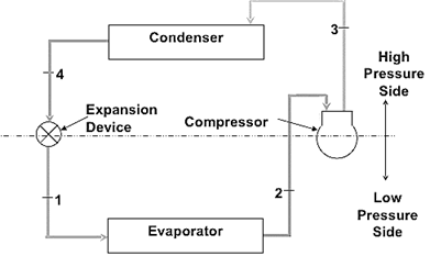
Fig. Vapour Compression refrigeration system
Highly compressed fluids tend to get colder when allowed to expand.
If pressure high enough:
- Compressed air hotter than source of cooling.
- Expanded gas cooler than desired cold temperature.
Two advantages:
- Lot of heat can be removed (lot of thermal energy to change liquid to vapour).
- Heat transfer rate remains high (temperature of working fluid much lower than what is being cooled).
Key Takeaways:
- The high pressure & temp vapor refrigerant is discharged into the condenser through the delivery or discharge valve.
- Some of liquid refrigerant evaporates as it passes through the expansion valve, but the greater portion is vaporized in the evaporator at the low pressure & temp.
- Compressed air hotter than source of cooling.
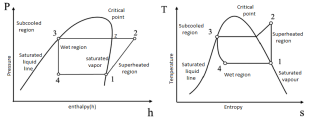
The P-H and T-S diagram for the simple vapor compression refrigeration cycle is shown in the figure for vapour entering the compressor is in dry saturation condition The dry and saturated vapour entering the compressor at point 1 that vapour compresses isentropic ally from point 1 to 2 which increases the pressure from evaporator pressure to condenser pressure At point 2 the saturated vapour enters the condenser where heat is rejected at constant pressure, due to rejection of heat decreases the temperature and change of phase takes place i.e. latent heat is removed and reaches to liquid saturation temperature at point 3 then this liquid refrigerant passed through expansion valve where liquid refrigerant is throttle keeping the enthalpy constant and reducing the pressure.
The suction pressure (or evaporator pressure) decreases due to the frictional resistance of flow of the refrigerant. Let us consider a theoretical vapour compression cycle 1'-2'-3-4' when the suction pressure decreases from ps to ps' as shown on p-h diagram. It may be noted that the decrease in suction pressure
- Decreases the refrigerating effect from (h1 - h4) to (h1'- h4') and
- Increases the work required for compression from (h2 – h1) to (h2' – h1')
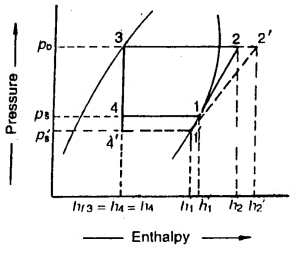
Since the C.O.P. Of the system is the ratio of refrigerating effect to the work done, therefore with the decrease in suction pressure, the net effect is to decrease C.O.P. Of the refrigerating system for the same amount of refrigerant flow. Hence with the decrease in suction pressure, the refrigerating capacity of the system decreases and the refrigeration cost increases.
Effect of Discharge Pressure:
The discharge pressure (or condenser pressure) increases due to frictional resistance of flow of the refrigerant. Let us consider a theoretical vapour compression cycle 1-2'-3'-4' when the discharge pressure increases from Pd to Pd' as shown on p-h diagram.
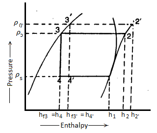
It may be noted that the increase in discharge pressure:
- Decreases the refrigerating effect from (h1 - h4) to (h1 - h4')
- Increases the work required for compression from (h2-h1) to (h2' - h1)
From above, we see that the effect of increase in discharge pressure is similar to the effect of decrease in suction pressure. But the effect of increase in discharge pressure is not as severe on the refrigerating capacity of the system as that of decrease in suction pressure.
Key Takeaways:
- Hence with the decrease in suction pressure, the refrigerating capacity of the system decreases and the refrigeration cost increases.
- Increases the work required for compression from (h2-h1) to (h2' - h1)
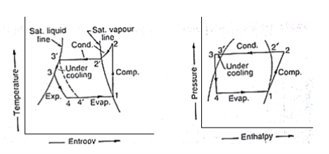
Effect of sub-cooling: sub-cooling is the process of cooling the liquid refrigerant below the condensing temperature for a given pressure. In figure the process of sub-cooling is shown by 2’-3’. As is evident from the figure the effect of sub-cooling is to increase the refrigerating effect. Thus, sub-cooling results in increase of C.O.P provided that no further energy has to be spent to obtain the extra cold coolant required.
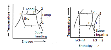
Effect of superheating: As shown in the figure a & b the effect of superheating is to increase the refrigerating effect, but this increase in the refrigerating effect is at the cost of increase in amount of work spent to attain upper pressure limit. Since the increase in work is more as compared to increase in refrigerating effect, therefore overall effect of superheating is to give a low value of C.O.P.
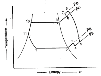
The actual vapour compression cycle differs from the theoretical vapour compression cycle in many ways, some of which are unavoidable and cause losses. The main deviations between the theoretical cycle and actual cycle are as follows:
- The vapour refrigerant leaving the evaporator is in superheated state.
- The compression of refrigeration is neither isentropic nor polytropic.
- The liquid refrigerant before entering the expansion valve is sub-cooled in the condenser.
- The pressure drops in the evaporator and condenser.
The actual vapour compression cycle on T-s diagram is shown. The various processes are discussed below
(a) Process 1-2-3: This process shows the flow of refrigerant in the evaporator. The point 1 represents the entry of refrigerant into the evaporator and the point 3 represents the exit of refrigerant from evaporator in a superheated state. The point 3 also represents the entry of refrigerant into the compressor in a superheated condition. The superheating of vapour refrigerant from point 2 to point 3 may be due to
(i) Automatic control of expansion valve so that the refrigerant leaves the evaporator as the superheated vapour.
(ii) Picking up of larger amount of heat from the evaporator through pipes located within the cooled space.
(iii) Picking up of heat from the suction pipe, i.e., the pipe connecting the evaporator delivery and the compressor suction valve.
In the first and second case of superheating the vapour refrigerant, the refrigerating effect as well as the compressor work is increased. The coefficient of performance, as compared to saturation cycle at the same suction pressure may be greater, less or unchanged. The superheating also causes increase in the required displacement of compressor and load on the compressor and condenser. This is indicated by 2-3 on T-s diagram as shown.
(b) Process 3-4-5-6-7-8: This process represents the flow of refrigerant through the compressor. When the refrigerant enters the compressor through the suction valve at point 3, the pressure falls to point 4 due to frictional resistance to flow. Thus, the actual suction pressure (Ps) is lower than the evaporator pressure (Pe). During suction and prior to compression, the temperature of the cold refrigerant vapour rises to point 5 when it comes in contact with the compressor cylinder walls. The actual compression of the refrigerant is shown by 5-6, which is neither isentropic nor polytropic. This is due to the heat transfer between the cylinder walls and the vapour refrigerant.
The temperature of the cylinder walls is some-what in between the temperatures of cold suction vapour refrigerant and hot discharge vapour refrigerant. It may be assumed that the heat absorbed by the vapour refrigerant from the cylinder walls during the first part of the compression stroke is equal to heat rejected by the vapour refrigerant to the cylinder walls. Like the heating effect at suction given by 4-5, there is a cooling effect at discharge as given by 6-7. These heating and cooling effects take place at constant pressure. Due to the frictional resistance of flow, there is a pressure drop i.e., the actual discharge pressure (Pd) is more than the condenser pressure (Pc).
(c) Process 8-9-10-11: This process represents the flow of refrigerant though the condenser. The process 8-9 represents the cooling of superheated vapour refrigerant to the dry saturated state. The process 9-10 shows the removal of latent heat which changes the dry saturated refrigerant into liquid refrigerant. The process 10-11 represents the sub-cooling of liquid refrigerant in the condenser before passing through the expansion valve.
This is desirable as it increases the refrigerating effect per kg of the refrigerant flow. It also reduces the volume of the refrigerant partially evaporated from the liquid refrigerant while passing through the expansion valve. The increase in refrigerating effect can be obtained by large quantities of circulating cooling water which should be at a temperature much lower than the condensing temperatures.
(d) Process 11-1: This process represents the expansion of subcooled liquid refrigerant by throttling from the condenser pressure to the evaporator pressure.
Key Takeaways:
- Thus, sub-cooling results in increase of C.O.P provided that no further energy has to be spent to obtain the extra cold coolant required.
- The vapour refrigerant leaving the evaporator is in superheated state.
- The superheating of vapour refrigerant from point 2 to point 3 may be due to
- The actual compression of the refrigerant is shown by 5-6, which is neither isentropic nor polytrophic
- The increase in refrigerating effect can be obtained by large quantities of circulating cooling water which should be at a temperature much lower than the condensing temperatures.
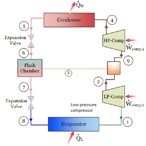
Fig. Schematic diagram of a two-stage vapor-compression refrigeration
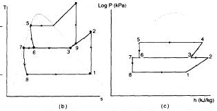
Fig. T-s and log P-h diagrams
Multistage refrigeration systems are widely used where ultra-low temperatures are required, but cannot be obtained economically through the use of a single-stage system. This is due to the fact that the compression ratios are too large to attain the temperatures required to evaporate and condense the vapor. There are two general types of such systems: cascade and multistage. The multistage system uses two or more compressors connected in series in the same refrigeration system. The refrigerant becomes denser vapor whilst it passes through each compressor. Note that a two-stage system can attain a temperature of approximately -65°C and a three-stage about – 100°C.
Multi-stage systems can be classified into:
a) Multi-compression systems
b) Multi-evaporator systems
c) Cascade systems, etc.
In refrigeration, flash-gas is refrigerant in gas form produced spontaneously when the condensed liquid is subjected to boiling.
The presence of flash-gas in the liquid lines reduces the efficiency of the refrigeration cycle.
It can also lead several expansion systems to work improperly, and increase superheating at the evaporator.
This is normally perceived as an unwanted condition caused by dissociation between the volume of the system, and the pressures and temperatures that allow the refrigerant to be liquid. Flash-gas must not be confused with lack of condensation, but special gear such as receivers, internal heat exchangers, insulation, and refrigeration cycle optimizers may improve condensation and avoid gas in the liquid lines.
Extraction of heat from a compressed gas between two stages of compression in order to improve the efficiency of compression.
The cooling of air between two stages of compression is known as intercooling. This reduces the work of compression and increases the specific output of the plant with a decrease in the thermal efficiency.
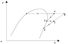
Instead of compressing the vapour in a single stage from state 1 to state 2’, if the refrigerant is compressed from state 1 to an intermediate pressure, state 2, inter cooled from 2 to 3 and then compressed to the required pressure (state 4), reduction in work input results. Intercooling not only reduces the work input but also reduces the compressor discharge temperature leading to better lubrication and longer compressor life.
Inter cooling using external water-cooled heat exchanger Depends on the availability of sufficiently cold water to which the refrigerant from low stage compressor can reject heat. The refrigerant at the inlet to the high stage compressor may not be saturated.
Key Takeaways:
- Note that a two-stage system can attain a temperature of approximately -65°C and a three-stage about – 100°C.
- It can also lead several expansion systems to work improperly, and increase superheating at the evaporator.
- Extraction of heat from a compressed gas between two stages of compression in order to improve the efficiency of compression.
- Intercooling not only reduces the work input but also reduces the compressor discharge temperature leading to better lubrication and longer compressor life.
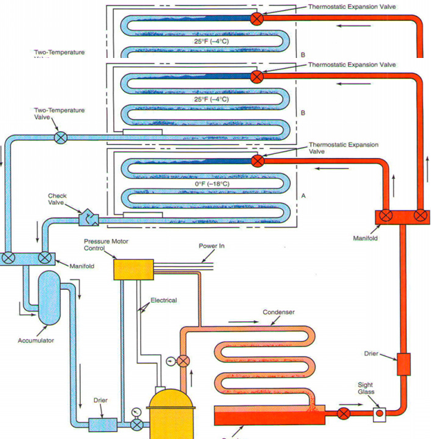
- Some business refrigeration structures have one condensing unit, related to or extra evaporators, Fig. 3-10, repeated (or extra) evaporator refrigeration structures are normally utilized in business refrigeration structures.
- Evaporators may also have the identical or exclusive temperatures of the evaporator.
- If the evaporator temperature is the identical, the gadget makes use of handiest the low aspect of the float, or TEV to govern the refrigerant.
- If or extra evaporating temperatures are desired (frozen meals temperature and the temperature of the cooling water, for example), the tool should be used to preserve one in every of evaporators for a decrease outside stress.
- Look on the diagram.
- Two temperature valve with inside the suction line (pinnacle left) maintains low stress liquid refrigerant (darkish blue) and steam (mild blue) in the evaporator at a better stress than the evaporator temperature is regulated via way of means of evaporating stress.
- The decrease the stress, the decrease the temperature. Non-go back valve is placed with inside the suction line coming from the evaporator cooler, and this prevents warmer, excessive-stress, low-aspect pairs (mild blue) and the penetration of bloodless evaporator, all through the off cycle.
- The vaporized refrigerant (mild blue) returns the motor-compressor. It will become an excessive-stress and excessive-temperature steam (pink mild).
- This steam is cooled in a refrigerator, becoming a liquid below excessive stress (darkish pink) is saved with inside the receiver till it is needed. Note the filter-dehydrator at the liquid line.
- This will assist refrigerant easy and dry Sight glass (fluid indicator mild) is frequently covered with inside the liquid line. A technician can use it to look if there are sufficient of refrigerant with inside the gadget, the Bubbles will factor to the shortage of refrigerant.
- This gadget, as shown, stress motor control. Working stress is occupied with the low aspect of the gadget. Line excessive-stress aspect is likewise covered motor control. It works protection tool which stops the motor if the condensing stress (excessive aspect) is just too excessive.
Key Takeaways:
- Evaporators may also have the identical or exclusive temperatures of the evaporator.
- Two temperature valve with inside the suction line (pinnacle left) maintains low stress liquid refrigerant (darkish blue) and steam (mild blue) in the evaporator at a better stress than the evaporator temperature is regulated via way of means of evaporating stress.
Cascade system was first used in 1877 by Pick let. Cascade system is just similar to the binary- vapour cycle used for the power plants. In a binary vapour cycle, a condenser for mercury works as a boiler for water as a boiler for water. Similarly, in the cascade system the condenser for low temperature cycle works as an evaporator for the high temperature cycle.
In cascade system, a series of refrigerants with progressively lower freezing points is used in a series of a single stage units. A two-stage cascade system using two refrigerants is shown in figure and its corresponding T-s diagram are shown in fig respectively.
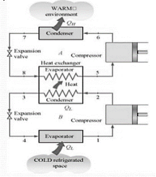
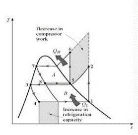
In this system a cascade condenser serves as an evaporator for high temperature cascade condenser system and a condenser for the low temperature cascade system the only useful refrigerating effect is produced in the evaporator of the low temperature cascade system. Thus, it permits the use of two different refrigerants, with thermodynamic properties favorable for the two temperature ranges. Further, the lubricating oil from one compressor cannot be carried away to another compressor. The temperature difference in low temperature cascade condenser and high temperature cascade evaporator is known as temperature overlap. The low temperature cascade system uses a refrigerant with low boiling temperature (such asR-13 or R-13BI).
Advantages of cascade refrigeration system:
1. It also reduces the lubricating problems since the lubricant associated with each refrigerant has to withstand a temperature range not more than 60oC, whereas in multistage system, the lubricant can have to be working over temperature range of order of 105oC.
2. Performance of cascade system can be improved through reducing temperature difference for heat transfer in the evaporator, condenser and cascade condenser, compare to larger compressors.
3. The performance of cascade system can be enhanced by reducing the temperature difference for heat transfer in evaporator, condenser and cascade condenser, and compare to larger compressors.
4. It avoids the problem of sub-atomic pressure which will octet in the evaporation if a single fluid is used in both the stages.
5. Using a cascade system power consumption can be reduced through about 9.5%.
Key Takeaways:
- Similarly, in the cascade system the condenser for low temperature cycle works as an evaporator for the high temperature cycle.
- The low temperature cascade system uses a refrigerant with low boiling temperature (such asR-13 or R-13BI).
- The performance of cascade system can be enhanced by reducing the temperature difference for heat transfer in evaporator, condenser and cascade condenser, and compare to larger compressors.
References:
1. Refrigeration and Air conditioning by C.P Arora, McGraw‐Hill
2. Refrigeration and Air conditioning, by Manohar Prasad, New Age International (P) Ltd. Pub.
3. Refrigeration and Air conditioning by R.C. Arora, PHI
4. Principles of Refrigeration by Roy J. Dossat. Pearson Education
5. Refrigeration and Air conditioning by Stoecker& Jones. McGraw‐Hill