Unit – 1
Introduction to Engineering Mechanics
Force is basically a vector quantity which may be either push or pull exerted during interaction of one object with other. Force is sort of interaction, when the interaction stops between objects, force is considered to be absent.
Types of Forces:
They can be divided as Contact Forces and Action at a distance type forces.
These forces act when there exists contact between surfaces or objects and are subdivided as:
Frictional Force: This type of force exists between the two surfaces making contact and having irregularities or roughness between the mating surfaces. E.g., Frictional force between the tyre of car and road causing it to wear and tear.
Tension Force: This type of force gets transmitted through ropes, wires or cables when some object is suspended or held using them. E.g., A block of material freely suspended using some rope and pulley arrangement.
Normal Force: This type of force exists when a particular object is placed on some other object, thus the weight of one object acts as a kind of force onto the other stable object. E.g., Book placed on the table.
Air resistance Force: This kind of force comes into action when motion of one object in presence of air, such that the air particle opposes the motion of that object, creating a kind of resistance force acting onto the body. E.g., An object falling from sky gets heated due to air resistance on the object.
Applied Force: This type of force is acted on an object externally, either to create a motion or retard the ongoing motion. E.g., Force applied by brakes to stop a moving vehicle.
Spring Force: This type of force exists when the spring which is compressed or stretched and gives a reaction force causing compression or stretching.
b. Action-at-a-Distance type Forces
These types of forces do not need to have physical contact between the two surfaces to exist. Some of these types of forces are
Gravitational Force: This force is considered to exist between any two bodies and is governed using Law of Gravitational Force given by Newton.
Electrical Force: This type of force is considered to be existing between two charged particles placed near each other causing pull or push between them.
Magnetic Force: This type of force is present between magnetic poles which may cause either pull or push of the magnets.
Effects of a force:
It may produce the effects on body on which it is acted as:
1. Motion of the body may be changed.
2. It may retard the motion of a body.
3. It may reduce the acting forces to make it stop or be in equilibrium
4. It may even create internal stresses in the body.
Characteristics of a force:
Following are the characteristics of a force:
1. Magnitude of the force (i.e., 100 N, 50 N, 20 kN, 5 kN, etc.)
2. The direction of the line, along which the force acts.
3. Nature of the force. This is denoted by placing an arrow head on the line of action of the force.
4. The point at which (or through which) the force acts on the body.
Consider a rigid body acted upon by various kinds of forces as shown in fig. like F1, F2, F3 etc. Thus, for a body to be in equilibrium, the resultant force, which is sum of all the forces and the resultant couple moment, both should be equal to zero. If these conditions are satisfied, then the body is said to be in equilibrium.
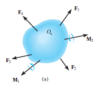
Thus, mathematically, the rigid body can be expressed using the following equations.


Thus, the method of solving the rigid body equilibrium problems involves the same steps as mentioned above.
Drawing a free-body diagram.
Using equations of equilibrium for solving the unknowns and desired quantities.
Thus, the only change takes place here is the equations of equilibrium that are used.


The procedure for solving is same as that of the particle equilibrium, just we need to consider the additional degree of freedom to be locked.
When two or more forces act, then we called it as the system of forces, like:
1. Coplanar forces: Those having line of action in same plane.
2. Collinear forces. Those whose line of action is in the same line.
3. Concurrent forces. Those which meet at one particular point in space.
4. Coplanar concurrent forces. Those having same plane and meet at one point.
5. Coplanar non-concurrent forces. Those who are in same plane but do not meet at a point.
6. Non-coplanar concurrent forces. Those, which meet at a point in space but are not in same plane.
7. Non-coplanar non-concurrent forces. Those, which do not meet at a point in space nor in the same plane.
These are the forces that are present in the same plane and they all meet at one particular point, thus being called coplanar concurrent force.
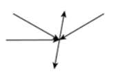
As shown in the figure above, the forces lie in the same plane and also meet at one particular point.
When many forces are acting, the overall effect can be considered in a single force. This single force is called resultant force and the given individual forces are called component forces.
Methods for the resultant force
Though there are many methods for finding out the resultant force of a number of given forces, yet the following are important from the subject point of view:
Analytical method includes the Parallelogram law of Vectors which is described as “If two forces, acting simultaneously on a particle, be shown by two sides of parallelogram, then the resultant will be the diagonal between these sides of parallelogram.”
Mathematically, resultant force,

Where R is the resultant force, A and B are component vectors and  is the angle between the two vectors, as shown below.
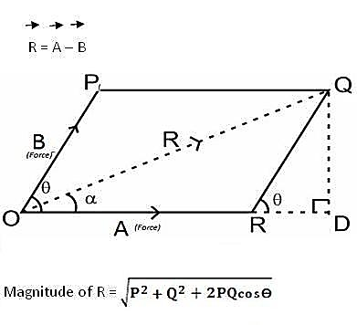
For finding the direction of resultant vector, we need to find the angle between A and R i.e.,  .
.

Method of resolution for the resultant force:
1. Horizontal resolution of forces is done and sum is taken (i.e., ∑H).
2. Vertical resolution of forces is done and sum is taken (i.e., ∑V).
3. The resultant R of the given forces will be given by the equation:

4. When the resultant is being inclined by an angle of θ, with the horizontal, we have

Thus, value of the angle θ will vary depending upon the values of ∑V and ∑H as discussed below:
1. When ∑V is +ve, the resultant makes an angle between 0° and 180°. But when ∑V is –ve, the resultant makes an angle between 180° and 360°.
2. When ∑H is +ve, the resultant makes an angle between 0° to 90° or 270° to 360°. But when ∑H is –ve, the resultant makes an angle between 90° to 270°.
Moment of a Force about a point:
When a force is applied such that it creates rotation at the point of application along line of application, this tendency to rotate is called as torque, or the moment of a force. For example, consider a wrench used to unscrew the bolt in Fig. below.
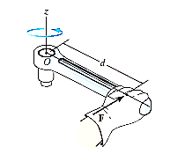
Note that if the force F is applied at an angle less than 900, Fig. (bas moment arm is smaller, it will be more difficult to turn.
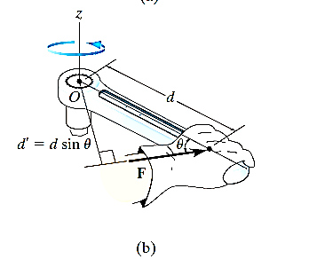
If F is applied along the length of wrench, Fig. (c), the moment arm will be zero. Hence moment will also be zero.
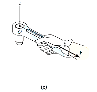
Thus, using the above observations, we can generalize accordingly.
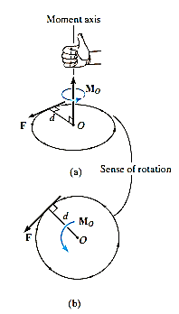
The magnitude of the moment is given by,

where d is the moment arm or perpendicular distance from the axis at point O to the line of action of the force. Units are. N*m or lb*ft.
Resultant Moment: For two-dimensional problems, where all the forces lie within the x–y plane, Fig. below, the resultant moment about point O (the z axis) can be determined by finding the algebraic sum of the moments caused by all the forces in the system. As a convention, we will generally consider positive moments as counterclockwise since they are directed along the positive z axis (out of the page). Clockwise moments will be considered to be negative. Doing this, the directional sense of each moment can be represented by a plus or minus sign. Thus, fig. below shows the sign conventions.
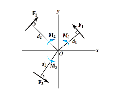

As we know that product of Scalar and vector quantity is always a vector quantity. Hence, the Moment of a force or torque is a vector quantity, and can be calculated using cross-product.
The moment of a force F about point O, or actually about the moment axis passing through O and perpendicular to the plane containing O and F, Fig. below, can be expressed using the vector cross product, namely,
MO = r X F
Here r represents a position vector directed from O to any point on the line of action of F. We will now show that indeed the moment when determined by this cross product, has the proper magnitude and direction.
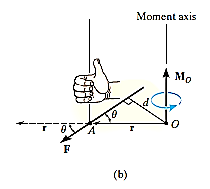
The magnitude of the cross product is defined as MO = rFsin where the angle
  is measured between the tails of r and F. To establish this angle, r must be treated as a sliding vector so that
  can be constructed properly. Since the moment arm d = rsin
 therefore,
MO = rFsin
MO = Fd
Cartesian Vector Formulation: If we establish x, y, z coordinate axes, then the position vector r and force F can be expressed as Cartesian vectors, Fig. (a) below.
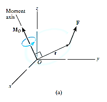
Formulating the equation in matrix format we have,

Where,
rx, ry, rz represent the x, y, z components of the position vector drawn from point O to any point on the line of action of the force.
Fx, Fy, Fz represent the x, y, z components of the force vector.
If the determinant is expanded, we will get the value of MO as,
MO = (ryFz – rzFy) i – (rxFz – rzFx) j + (rxFy – ryFx) k
Moment of a Force about a Specified Axis:
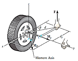
Sometimes, the moment produced by a force about a specified axis must be determined. For example, suppose the lug nut at O on the car tire in Fig. above needs to be loosened. The force applied to the wrench will create a tendency for the wrench and the nut to rotate about the moment axis passing through O; however, the nut can only rotate about the y axis. Therefore, to determine the turning effect, only the y component of the moment is needed, and the total moment produced is not important. To determine this component, we can use either a scalar or vector analysis.
Scalar Analysis: To use a scalar analysis in the case of the lug nut in Fig. above, the moment arm perpendicular distance from the axis to the line of action of the force is dy = d cos  . Thus, the moment will be
MOy = F (d cos )
)
Vector Analysis: To find the moment of force F in above figure about the y axis using a vector analysis, we must first determine the moment of the force about any point O on the y axis by applying MO = r x F. The component My along the y axis is the projection of MO onto the y axis. It can be found using the dot product discussed above, so that My = j*MO = j*(r x F) where j is the unit vector for the y axis.
We can generalize this approach by letting ua be the unit vector that specifies the direction of the axis shown in Fig. 4–21. Then the moment of F about the axis is

This combination is referred to as the scalar triple product. If the vectors are written in Cartesian form, we have


Equivalent Moment:
The equivalent moment acting on a system of forces can be calculated as illustrated in the following examples:
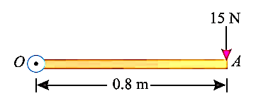
e.g., 5: A force of 15 N is applied perpendicular to the edge of a door 0.8 m wide as shown in Fig. below. Find the moment of the force about the hinge.
Solution:
Given: Force applied (P) = 15 N and width of the door (l) = 0.8 m
Moment when the force acts perpendicular to the door as shown in fig.
We know that the moment of the force about the hinge is given as,
MO = P × l = 15 × 0.8 = 12.0 N-m
If the force is to be applied at a particular angle according to fig. below,
Then the calculations are done in following procedure.
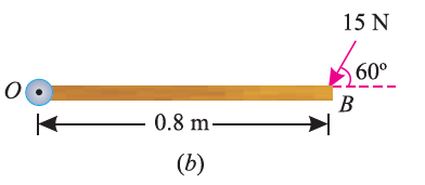
As the force applied in the question above is inclined at an angle of 600 with the horizontal, we can calculate the moment of force by two methods, either by finding out the perpendicular distance between the hinge and the line of action of the force as shown in Fig. (a) or by finding out the vertical component of the force as shown in Fig. (b) below.

From the geometry of Fig. (a), we find that the perpendicular distance between the line of action of the force and hinge,
OC = OB sin 60° = 0.8 × 0.866 = 0.693 m
∴ Moment = 15 × 0.693 = 10.4 N-m
In the second case, we know that the vertical component of the force
= 15 sin 60° = 15 × 0.866 = 13.0 N
∴ Moment = 13 × 0.8 = 10.4 N-m
Calculating the resultant of Force System:
As discussed above, the equivalent force can be calculated using two methods, either by Analytical method like simple laws of vector addition, subtraction or Parallelogram law of vector addition or Method of Resolution.
e.g.,1: Two forces of 100 N and 150 N are acting simultaneously at a point. What is the resultant of these two forces, if the angle between them is 45°?
Solution:
Here, the two forces are First force (F1) = 100 N; Second force (F2) = 150 N and angle between F1 and F2 (θ) = 45°.
We know that using parallelogram law of vector addition, we get,


R = 232 N.
In this way, we can calculate the resultant between two force vectors.
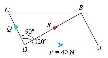
e.g.,2: Two forces act at an angle of 120°. The bigger force is of 40 N and the resultant is perpendicular to the smaller one. Find the smaller force.
Solution:
In this problem, one of the forces is given as 40 N and the angle between the two forces is given as 1200, as depicted in fig below. Also, the angle between the resultant and smaller force is given as 900. Thus, the resultant parallelogram is shown below.
Angle between the forces ∠AOC = 120°, Bigger force (F1) = 40 N and angle between the resultant and F2 (∠BOC) = 90°;
Let F2 = Smaller force in N
From the geometry of the figure, we find that ∠AOB,
α = 120° – 90° = 30°
We know that

Now,
By putting the values as,
α = 300
 = 1200
F1 = 40 N, we get,


Thus,
F2 = 20 N
In this way, we can calculate the unknown quantities by analytical method of force resolution.
Now, we will understand the procedure of finding the resultant or unknown quantity using the method of resolution of forces vertically and horizontally, as discussed earlier.
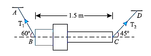
e.g., 3: A machine component 1.5 m long and weight 1000 N is supported by two ropes AB and CD as shown in Fig. given below. Calculate the tensions T1 and T2 in the ropes AB and CD.
Solution:
Given: Here, weight of the component is 1000 N. Thus, for solving this example we will resolve the forces vertically as well as horizontally. Initially we will resolve the forces horizontally. As the component is in equilibrium horizontally, (i.e., along BC) we will get:
T1 cos 60° = T2 cos 45°
Thus, T1 = 1.414 T2
Now, we will resolve the tension and self-weight vertically, we will get,
T1 sin 60° + T2 sin 45° = 1000
(1.414 T2) 0.866 + T2 × 0.707 = 1000
Thus, T2 = 518.1 N
Therefore, T1 = 1.414*518.1
T1 = 732.6 N.
In this way, using the resolution of forces vertically and horizontally, we can get the required quantities.
If we wanted to find the equivalent force of many forces acting on a body, we can use the resolution of forces method. It can be explained using the example below.
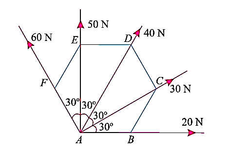
e.g., 4: The forces 20 N, 30 N, 40 N, 50 N and 60 N are acting at one of the angular points of a regular hexagon, towards the other five angular points, taken in order. Find the magnitude and direction of the resultant force.
Solution:
The system of forces is as shown in the fig. above. So, for finding the equivalent force, we will resolve the forces horizontally and vertically, and then calculate the resultant force.
Now, resolve the above-mentioned force system horizontally, (i.e., Along AB) we will get,
ΣH = 20 cos 0° + 30 cos 30° + 40 cos 60° + 50 cos 90° + 60 cos 120° N
= (20 × 1) + (30 × 0.866) + (40 × 0.5) + (50 × 0) + 60 (– 0.5) N
= 36 N
Also, resolving the force system vertically, we get,
ΣV = 20 sin 0° + 30 sin 30° + 40 sin 60° + 50 sin 90° + 60 sin 120° N
= (20 × 0) + (30 × 0.5) + (40 × 0.866) + (50 × 1) + (60 × 0.866) N
= 151.6 N
Now, for calculating the magnitude of resultant force of this system,


R = 155.8 N
For finding the direction of resultant force vector,
Let, θ = Angle, which the resultant force makes with the horizontal (i.e., AB).
We will use the formula,


Thus, θ = 76.6°
In this way, using the resolution of forces method, we can find the equivalent force of the system.
Couple:
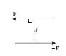
Couple can be defined as combination of two forces which are of equal magnitude but are opposite in direction, and are separated by a perpendicular distance d as shown in figure below. This can be illustrated by considering that when we are driving a car, to take a right turn, the right hand imparts a pull downwards on the steering wheel and the left hand imparts a push on steering wheel upwards, thus creating a couple. This moment created by couple is known as Couple Moment.
This, in scalar formulation, Formula for couple is given as,

Where F is magnitude of force and d is perpendicular distance between the forces. For finding the direction, the same method is used which is used for moment about a point, i.e. Right Hand rule.
If more than two moments are created, their resultant can be determined using vector addition. i.e., MR = M1 + M2.
Generalized equation for more than one couple moments is given as,

A system of forces is said to be in equilibrium if the resultant force which is summation of all the forces acting on the body is zero. If we consider in Static Equilibrium, then the system is considered to be in rest condition. Thus, for a system to be in rest condition, it needs to satisfy the Newton’s First Law of motion. Thus, the generalized equation for a system to be in equilibrium states that resultant force acting on the system should be zero for the system to be in equilibrium,
i.e.,  .
.
This is further explained in the topic of equations of equilibrium for the system.
To apply the equation of equilibrium, we have to consider all types of forces (ΣF) which are acting on the particle. A drawing in which all the forces are depicted is called free body diagram (FBD).
Process to Draw a Free-Body Diagram
To construct a free body diagram, the following three steps are necessary.
Imagine that the particle is to be isolated from its environments by drawing its outlined shape.
b. Show All the forces.
Then on this sketch, show all the types of forces. Identify Each Force that are known and unknown and display them.
c. Identify each force
Known forces are displayed with magnitude and direction. Letters are used to represent the magnitudes and directions of forces that are unknown.
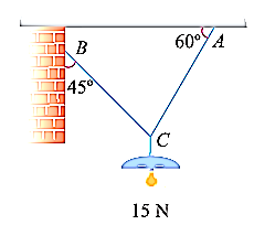
For understanding the free-body diagram, we will consider the following example:
Suppose, in this example there are two strings (AC and BC) attached to an object at point C. Thus, the first step involves drawing a simple diagram representing the outline of all components.
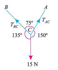
Then, we need to show all the forces that are contributing in the given diagram. Here, there is 15 N force acting at point C, and there is tension in strings BC and AC due to 15 N force acting at C. Thus, identifying and displaying these forces onto the outline diagram is the second step.
The third step is finding the magnitude and direction of the forces and displaying them on the outline diagram. Using these steps, we can draw the free-body diagram as shown below.
1. If the body moves in any direction, it means that there is a resultant force acting on it. In other words, the horizontal component of all the forces (Σ H) and vertical component of all the forces (ΣV) must be zero. Mathematically,
Σ H = 0 and Σ V = 0
2. If there is rotation of body, without moving, that means there is couple acting. In other words, the resultant moment of all the forces (Σ M) must be zero. Mathematically,
Σ M = 0
3. If the body moves in any direction and at the same time it rotates about itself, if means that there is a resultant force and also a resultant couple acting on it. In other words, horizontal component of all the forces (Σ H), vertical component of all the forces (Σ V) and resultant moment of all the forces (Σ M) must be zero. Mathematically,
Σ H = 0 Σ V = 0 and Σ M = 0
4. If the body is completely at rest, it means there is no force nor any couple acting on it. A little consideration will show, that in this case the following conditions are already satisfied:
Σ H = 0 Σ V = 0 and Σ M = 0
The above-mentioned equations are known as the conditions/equations of equilibrium.
Basically, force of friction can be broadly classified into the following types:
Static Friction
Dynamic Friction, which is further subdivided as Sliding and Rolling friction
Fluid Friction
As we know friction is force of resistance offered to external forces coming onto the system. Hence, the types of forces of friction that might be present are as mentioned above.
In solid surfaces, static, sliding and rolling friction are present. Static type of friction is always strongest than all others, which is then followed by sliding friction, and then by rolling type of friction, which is weakest of all above.
Fluid friction is present in case of fluid contact, like liquids and gases. E.g., Flow of water or fluid through the pipe.
Some of the other types of friction, depending upon the type of application may be as:
Lubricated friction is a type of fluid friction present in between the surface of material and lubricating fluid layer present.
Skin friction is a type of drag present between the two surfaces in contact during the motion of a body over a surface.
Internal friction is type of force of resistance present in a body during any deformation of that body taking place.
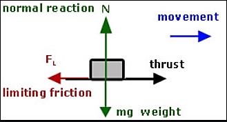
In case of Static friction, the two surfaces in contact are at rest. This is shown in figure below.
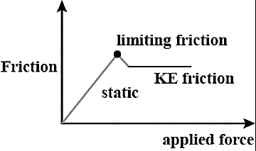
Thus, according to the Newton’s First Law of Motion, any object tends to be in rest or motion, unless an external unbalanced force is applied on it. Thus, in this case, if two surfaces are in static condition, there is no unbalanced force acting on them. Now, if small amount of force is applied on the block, as shown in the figure as movement, then in absence of friction, the block should move. But as friction is present, the block will stay in rest condition. Now, we will start increasing the applied force in the form of movement shown in fig. till the point when the movement applied by external force overcomes the friction present. Thus, the minimum value of force that needs to be applied to make the block move from its rest condition, is called as limiting friction. When the applied force exceeds the limiting friction value, block will start to move.

Thus, the value of limiting friction is maximum, compared to static and KE friction depicted in graph shown.
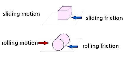
The coefficient of friction given for all the mentioned cases will follow the laws of friction mentioned below.
Coulomb friction is also known as Dry friction and was named after C. A. Coulomb who extensively studied this phenomenon. Dry friction is considered to exist between the two surfaces of objects which are in contact when there is absence of any kind of fluid lubrication.
Dry friction may take place either due to adhesion between the surfaces, or roughness or contamination of surfaces taking place.
As there is loss of mechanical energy in the form of heat during the frictional process, it turns out to be non-conservative force that is path dependent.
The force of friction is always applied in a manner that opposes the movement created within the two surfaces. Any object moving on a road or any surface slows down and then eventually stops.
Dry friction is can be further classified into static friction which is between non-moving surfaces, and kinetic friction which is between moving surfaces.
The laws are discussed as:
Laws of Static Friction:
Following are the laws of static friction:
1. The force of friction always act in direction which is opposite to motion of body.
2. The magnitude of force of friction is equal to the force acting on the body externally.
3. There is constant ratio between limiting frictional force and the normal reaction forces. Mathematically:
(F/R) = Constant
where F = Limiting friction, and R = Normal reaction.
4. The force of friction does not depend on the area of contact between the two surfaces.
5. There is dependency of frictional force on roughness of the surfaces.
Laws of Kinematic or Dynamic Friction:
Following are the laws of kinetic or dynamic friction:
1. The force of friction always act such that it opposes the motion of body.
2. There is a constant ratio between kinetic motion and normal reaction. But this ratio is slightly less when it comes to limiting friction.
3. For medium speeds, the force due to friction stays constant. But it decreases somewhat when the speed increases.
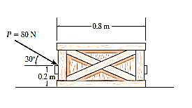
e.g., 1: The uniform crate shown in Fig. below has a mass of 20 kg. If a force P = 80 N is applied to the crate, determine if it remains in equilibrium. The coefficient of static friction is  = 0.3.
Solution:
The first step is free-body diagram i.e.
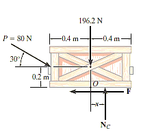
Free-Body Diagram. As shown in Fig. diagram below, the resultant normal force NC acts at a distance of x from the centre line of crate for countering the tilting effect caused by P. Hence, there are three unknowns, F, NC and x, which can be solved by equations of equilibrium.
Equations of equilibrium:
Σ Fx = 0
80 cos 30° N - F = 0
Σ Fy = 0
-80 sin 30° N + NC - 196.2 N = 0
Σ M = 0
80 sin 30° N10.4 m2 - 80 cos 30° N10.2 m2 + NC (x) = 0
Thus, solving the above equations, we get,
F = 69.3 N
NC = 236 N
x = -0.00908 m = -9.08 mm
As value of x is negative, hence it acts to left of centre line of the crate. There will be no tipping since x < 0.4 m. Fmax =  Nc = 0.3(236 N) = 70.8 N. Since F that we got is 69.3 N < 70.8 N, the crate will not slip.
For understanding motion of bodies, using friction, we will discuss two types of motion.
When the object is lying onto the surface, without any inclination, horizontally.
When the surface is inclined at an angle with the horizontal.
Thus, in first case for solving problems related to dry friction and motion of bodies, when the surface is horizontal, we follow the steps mentioned below.
Free-Body Diagrams:
Draw the necessary free-body diagrams, and unless it is stated in the problem that impending motion or slipping occurs, always show the frictional forces as unknowns (i.e., do not assume  ).
).
Initially find the number of unknowns and then compare with the available equations of equilibrium.
If unknowns are more than equations available, then frictional equation is also considered.
If the equation  is to be used, it will be necessary to show F acting in the correct sense of direction on the free-body diagram.
Equations of Equilibrium and Force of Friction.
Apply the equations of equilibrium and the necessary frictional equations (or conditional equations if tipping is possible) and solve for the unknowns.
Cartesian Vectors can be used if there is three-dimensional figure and it becomes difficult to solve it.
The steps mentioned above can be used for solving the numerical related to dry friction, and the surface being horizontal which are explained below.
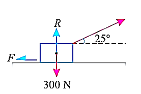
e.g., 2: A body of weight 300 N is lying on a rough horizontal plane having a coefficient of friction as 0.3. Determine the magnitude of the force, which is needed to move the body, acting at 25° by the horizontal.

Solution:
Given:
Weight of the body (W) = 300 N; Coefficient of friction (μ) = 0.3 and
angle made by the force with the horizontal (α) = 25°
Let P = Magnitude of the force, which can move the body, and
F = Force of friction.
Initially, we will solve the problem in horizontal direction as,

The next step is to resolve the force in vertical direction, we get,


The force of friction (F) is given as,


Hence, P = 87.1 N.
e.g., 3: A body, which is positioned on a rough horizontal plane, needs a pull of 180 N inclined at 30° to the plane just for moving. Also, it was found that a push of 220 N which is inclined at 30° to the plane also moved the body. Find out the weight of the body and the coefficient of friction present here.
Solution:
Given: Pull = 180 N; Push = 220 N and angle at which force is inclined with horizontal plane (α) = 30°
Let W = Weight of the body
R = Normal reaction, and
μ = Coefficient of friction.
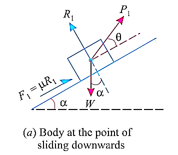
First of all, consider a pull of 180 N acting on the body. We know that in this case, the force of friction (F1) will act towards left as shown in Fig. (a).
Resolving the forces horizontally,
F1 = 180 cos 30° = 180 × 0.866 = 155.9 N
and now resolving the forces vertically,
R1 = W – 180 sin 30° = W – 180 × 0.5 = W – 90 N
We know that the force of friction (F1),
Now consider a push of 220 N acting on the body. We know that in this case, the force of friction (F2) will act towards right as shown in Fig. (b).
Resolving the forces horizontally,
F2 = 220 cos 30° = 220 × 0.866 = 190.5 N
and now resolving the forces horizontally,
R2 = W + 220 sin 30° = W + 220 × 0.5 = W + 110 N
We know that the force of friction (F2),
Dividing equation (i) by (ii)
W = 991.2 N
Now substituting the value of W in equation (i),
μ = 0.173
In this way, numerical based on dry friction can be solved.
In the second case, when the surface makes some angle with the horizontal, the formula used can be derived as,
Let’s find out the minimum force that will keep the block in equilibrium and avoid sliding downwards.
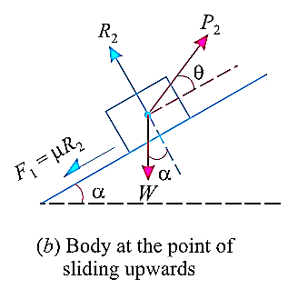
W is the Weight of the body,
α is the between the inclined plane and horizontal
θ is the angle between the force applied and inclined surface,
R is the normal reaction,
μ is the coefficient of friction and
φ is angle of friction, such that  .
.
When we resolve the forces along the inclined plane, we will get,

Similarly, when we resolve the forces vertically,

Now, solving the two equations, we get,


Thus,

Here, if we substitute,  we get,

Then, if we multiply and divide by cos , we get,

Now, for maximum force that will keep the body in equilibrium and not slide upwards can be determined in similar manner.
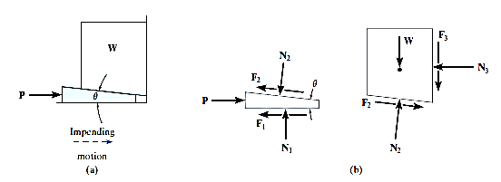
Resolving the forces shown in fig. above along the inclined plane.

Now, resolving in direction perpendicular to the plane,

Then,


Thus,

Here, if we substitute,  we get,

Then, if we multiply and divide by cos , we get,

A Wedge can be considered as a simple device, that is used to transform or slightly adjust heavy loads and their positions, when the load is supported at right angles to its surface. Consider, for example, the wedge shown in Fig. (a), which is used to lift the block by applying a force to the wedge. Free-body diagrams of the block along with wedge shapes are shown in Fig. (b). Here we have excluded the weight of the wedge since it is usually small compared to the weight W of the block. Also, note that the frictional forces F1 and F2 must oppose the motion of the wedge.
Likewise, the frictional force F3 of the wall on the block must act downward so as to oppose the block’s upward motion. Hence the moment equilibrium equations will not be considered. There are seven unknowns, consisting of the applied force P, needed to cause motion of the wedge, and six normal and frictional forces. The seven available equations consist of four force equilibrium equations,  Fx = 0,
  Fy = 0 applied to the wedge and the block, and three of the frictional equations, F =
  N, applied at each surface of contact.
If the block is to be lowered, then the frictional forces will all act in a sense opposite to that shown in Fig. (b). Provided the coefficient of friction is very small or the wedge angle  is large, then the applied force P must act to the right to hold the block. Otherwise, in order the block, P may have reverse direction. If without application of P, block is held with the help of frictional forces, then the wedge is referred to as self-locking.
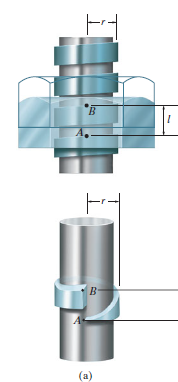
In most cases screws are used as fasteners; however, in many types of machines they are incorporated to transmit power or motion from one part of the machine to another. A square threaded type of screw can be used when large amount of forces is to be transmitted along the axis of the screw. In this section we will analyze the forces acting on square-threaded screws. The analysis of other types of screws, such as the V-thread, is based on these same principles.
For the purpose of analysis, a square threaded screw, as in Fig. below, can be considered a cylinder having an inclined square ridge or thread wrapped around it. If we unwind the thread by one revolution, as shown in Fig., the slope or the lead angle  is determined from
  = tan-1(l/2πr). Here l and 2πr are the vertical and horizontal distances between A and B, where r is the mean radius of the thread. The distance l is called the lead of the screw and it is equivalent to the distance the screw advances when it turns one revolution.
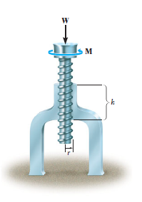
Upward Impending Motion: Let us now consider the case of a square-threaded screw that is subjected to upward impending motion caused by the applied torsional moment M, Fig. below. A free-body diagram of the entire unraveled thread can be represented as a block as shown in Fig. above. The force W is the vertical force acting on the thread or the axial force applied to the shaft, Fig. below, and M/r is the resultant horizontal force produced by the couple moment M about the axis of the shaft. The reaction R of the groove on the thread, has both frictional and normal components, where  . The angle of static friction is
  = tan-1(F/N) = tan-1
 . Applying the force equations of equilibrium along the horizontal and vertical axes, we have
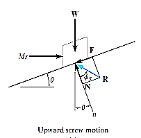
Σ Fx = 0
M/r - R sin ( +
+  ) = 0
) = 0
Σ Fy = 0
R cos ( +
+  ) - W = 0
Eliminating R from these equations, we obtain
M = rW tan ( +
+  )
)
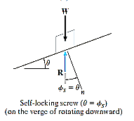
Self-Locking Screw: A screw is said to be self-locking if it remains in place under any axial load W when the moment M is removed. For this to occur, the direction of the frictional force must be reversed so that R acts on the other side of N. Here the angle of static friction  becomes greater than or equal to
  , If
, If  then R will act vertically to balance W, and the screw will be on the verge of winding downward.
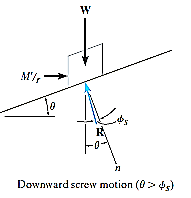
Downward Impending Motion: ( If a screw is self-locking, a couple moment M’ must be applied to the screw in the opposite direction to wind the screw downward
  .This causes a reverse horizontal force M’/r that pushes the thread down as indicated in Fig. below. Using the same procedure as before, we obtain
M’ = rW tan ( )
)
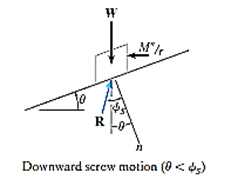
Downward Impending Motion:  . If the screw is not self-locking, then there is need for applying a moment M” for preventing the screw from winding downward. Here, a horizontal force M”/r is required to push against the thread to prevent it from sliding down the plane, Fig. below. Thus, the magnitude of the moment M” required to prevent this unwinding is
M– = Wr tan ( )
)
References:
1. Irving H. Shames (2006), Engineering Mechanics, 4th Edition, Prentice Hall
2. F. P. Beer and E. R. Johnston (2011), Vector Mechanics for Engineers, Vol I - Statics, Vol II, – Dynamics, 9th Ed, Tata McGraw Hill
3. R. C. Hibbler (2006), Engineering Mechanics: Principles of Statics and Dynamics, Pearson Press.
4. Andy Ruina and Rudra Pratap (2011), Introduction to Statics and Dynamics, Oxford University Press
5. Shanes and Rao (2006), Engineering Mechanics, Pearson Education