Unit - 3
Basic Structural Analysis Covering
A system of forces is said to be in equilibrium if the resultant force which is summation of all the forces acting on the body is zero. If we consider in Static Equilibrium, then the system is considered to be in rest condition. Thus, for a system to be in rest condition, it needs to satisfy the Newton’s First Law of motion. Thus, the generalized equation for a system to be in equilibrium states that resultant force acting on the system should be zero for the system to be in equilibrium,
i.e.  .
.
This is further explained in the topic of equations of equilibrium for the system.
For any three-dimensional force system, as shown in Fig. Below, we can resolve the forces into their respective i, j, k components, so that
Σ Fx i + Σ Fy j + Σ Fz k = 0
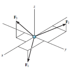
Fig: 1
To satisfy this equation we require,
Σ Fx = 0
Σ Fy = 0
Σ Fz = 0
These three equations state that the algebraic sum of the components of all the forces acting on the particle along each of the coordinate axes must be zero. Using these equations mentioned we can solve for maximum three of the unknowns, shown by coordinate direction angles or magnitudes of forces shown on the particle’s free-body diagram.
For solving three dimensional problem we can use the following procedure.
Free Body Diagram:
• In any orientation, establish x and y axes.
• Then mark all the known and unknown forces in figure.
• Unknown forces are also assumed and plotted.
Equations of Equilibrium.
• Apply the equations of equilibrium, Σ Fx = 0, Σ Fy = 0 and Σ Fz = 0.
• Initially we can display as a Cartesian vector if it becomes to solve the problem regularly, substitute these vectors into Σ F = 0 and then set the i, j, k components equal to zero.
• If the resultant comes out to be negative value, it means that the direction needs to be reversed for that is already considered.
Problems in Three-dimensions:
Q. The 10-kg lamp in Fig. Below is suspended from the three equal-length cords. Find the smallest vertical distance s from the ceiling if force built in cord is not to go beyond 50 kN.
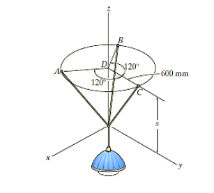
Fig. 2
Solution:
For solving these three-dimensional numerical, we will follow the same procedure mentioned above.
Free-Body Diagram: Because of symmetry, the distance are as  mm. It follows that from Σ Fx = 0 and Σ Fy = 0, the tension T in each cord will be the same. Also, the angle between z axis and every cord is
  .
.
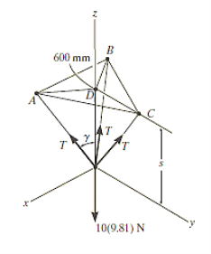
Fig: 3
Equation of Equilibrium: Applying the equilibrium equation along the z-axis, with T = 50 N, we have
Σ Fz = 0;
3[(50 N) cos  ] - 10(9.81) N = 0
 = cos-1 (98.1 / 150)
= 49.160
Now,
By geometry shown in free-body diagram,
Tan 49.160 = (600 / s)
s = 519 mm
In this way, three-dimensional problems are solved using equations of equilibrium.
Q: A 90-lb load is being suspended from a hook as shown in Fig. Below. If the load is being supported by two cables and a spring having a stiffness of k = 500 lb/ft, find the force in the cables and the stretch of the spring for equilibrium. Cable AD lies in the x–y plane and cable AC lies in the x–z plane.
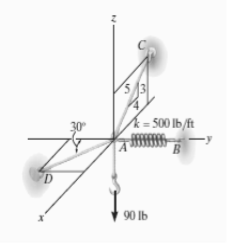
Fig: 4
Solution:
Initially, force in spring is determined to determine stretching of spring.
Free-Body Diagram. A point is chosen for all analysis as all the points are concurrent here. The free-body diagram for the problem is shown in Fig. Below.
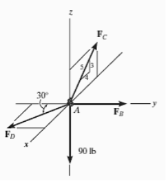
Fig: 5
Equations of Equilibrium. We can resolve each force in x, y and z components, and so we can use three scalar equations of equilibrium. Considering components directed along each positive axis as “positive,” we have
Σ Fx = 0
FD sin 30° - (4/5) FC = 0
Σ Fy = 0
-FD cos 30° + FB = 0
Σ Fz = 0
(3/5) FC – 90 lb = 0
Thus, solving the above-mentioned equations, we get,
FC = 150 lb
FD = 240 lb
FB = 207.8 lb
The stretch of the spring is therefore
FB = ksAB
207.8 lb = (500 lb/ft) (sAB)
sAB = 0.416 ft
In case of 3D equilibrium problems for rigid bodies, we need to consider additional degree of freedom about z axis to be locked. Thus, the equations of equilibrium are,


The procedure for solving is same as that of the particle equilibrium, just we need to consider the additional degree of freedom to be locked.
Truss:
A truss is a structure which is made of slender members those are joined together at the end points. Planar trusses lie in one single plane and these are frequently used to support some of the bridges and roofs. Fig. (a) is a typical roof-supporting truss used for construction. Since this loading turns in the similar plane as the truss, Fig. (b), the analysis of the forces developed in the truss members will be two-dimensional.
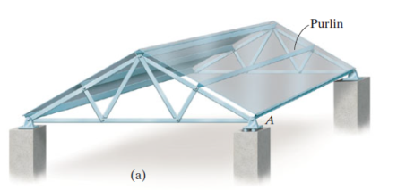
Fig: 6
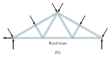
Fig: 7
Now, for understanding the considerations made during solving of truss problems, let us understand by the following example:
Let us consider a bridge, as shown in the fig. Below.
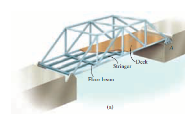
Fig: 8
Here, the load is transmitted from the Deck to the Stringer, as shown in fig. Then, from Stringer, the load gets transmitted to Floor Beam. From the floor beam, the load is transmitted to the joints that holds the bridge, i.e. Side Truss. Thus, we understand that the side truss will be coplanar, as shown below (b).
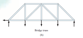
Fig: 9
If the span is larger, then for accommodation of thermal expansion or compression of members of bridge, rollers or rockers are used that is shown in above fig. (a), point named as A.
Thus, while design of such kind of truss, we mention some of the assumptions.
- All loadings are applied at the joints present:
Mostly, the loads applied in case of bridges or trusses is at joints only, hence this assumption is mostly true. But, if the weight of an object is to be considered, then the weight is supposed to be applied at each end point of the member and half in magnitude of its original magnitude in the form of vertical force.
2. The members should be joined using smooth pins:
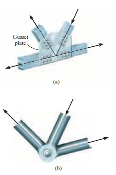
Fig: 10
As shown in the fig. Above, most of the members are considered to be joined using bolting or welding method to a gusset plate, fig.(a), or by directly putting a bolt through the endpoints as shown in fig.(b).This will be true if the members of truss and bolt applied are concurrent.
Method of joints
This method is useful in finding forces in all the members or number of members of a truss. Following are the basic steps in analysis of truss by method of joints.
- Step 1: Check the stability of truss by using n = 2j-3.
- In case of a Cantilever truss we can check the stability by using n = 2j-4.
- Step 2: Consider F.B.D. Of entire truss and compute the reaction components using three conditions of equilibrium.
- Determination of support reactions may not be necessary in the case of cantilever truss.
- Step 3: Select a joint such that there exist maximum two unknown forces.
- Step 4: Draw F.B.D. Of selected joint by assuming forces in members as away from the joint (i.e. assume tensile force)
- Step 5: The forces at a joint are concurrent and each joint is in equilibrium so, apply two conditions of equilibrium ΣFx = 0 and ΣFy = 0.
- Step 6: Find out some forces by observation or by inspection. (if any)
- Step 7: Repeat the procedure by selecting different joints and find out forces in all the members of truss.
- Step 8: Tabulate the results in a 'Force Table' using positive as tensile and negative as compressive.
- Step 9: Draw final F.B.D. Of truss showing magnitudes natures of all external as well as internal forces.
Forces by Observation:
Observation 1: Two forces joint
- If a joint carries only two forces which are non-collinear, for equilibrium of joint both forces must be equal to zero.

Fig: 11
Observation 2: Three forces joint
- If a joint carries only 3 forces and out of which if two are collinear, the third force must be equal to zero and two collinear forces must be equal and opposite.

Fig: 12
Observation 3: Four forces joint
- If a joint carries four forces with two pairs of collinear forces [plus joint or cross joint] the collinear forces must be equal and composite.
In Fig.(a) and Fig. (b) F1 = F2 and F3 = F4.
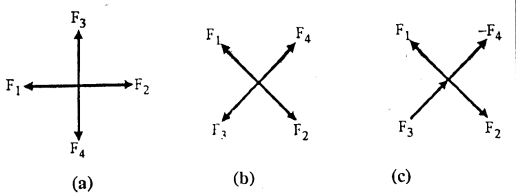
Fig:13
Important Note:
For above four forces joint if a force acting away from joint the opposite collinear force must be tensile, but if a force is acting towards the joint, opposite collinear force must be compressive (-ve)
In Fig.(c).
F₁ = F₂ but F3 = -F4
Or F3 = F4(compressive)
Method of Sections:
This method is particularly used when magnitude and nature of forces in few members (limited numbers) are required to be found out.
Steps in method of Section:
- Step 1: Check the stability of a truss.
- Step 2: Find out reaction components by drawing F.B.D. Of truss and by applying conditions of equilibrium.
- Step 3: Select a section, cutting maximum three members (maximum three unknown forces) in which forces are to be determined.
- Step 4: With reference to imaginary section, now there are two parts of truss, select either of the parts and draw F.B.D. Of that part, by assuming forces in cut members as towards the section. (away from joints),
- Note: The Free body diagram of considered part include only external forces acting on that part as well as internal tensile forces in cut members.
- Step 5: Now apply
 = 0 at different joints to find out internal forces.
Important tip 1:
- A section can cut more than 3 members but the unknown forces should not exceed 3.
Important tip 2:
- In case of cantilever truss no need to calculate reaction components but after selecting a section draw F.B.D. Of free part only (without reaction components at wall it is not possible to draw F.B.D. Of part consisting wall).
- In a truss system, a few contributors aren't sporting any pressure. This known as a zero-pressure member.
- This member can be delivered to growth truss stability. Identifying those contributors will simplify the technique of reading truss.
- These zero pressure contributors can be essential for the stableness of the truss at some stage in production and to offer assist if the carried out loading is changed.
- The zero-pressure contributors of a truss can typically be decided through inspection of the joints, and that they arise in cases.
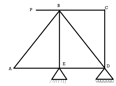
Fig: 14
- In fig at joint A and Joint C, there is no external forces acting, therefore they are zero force members.
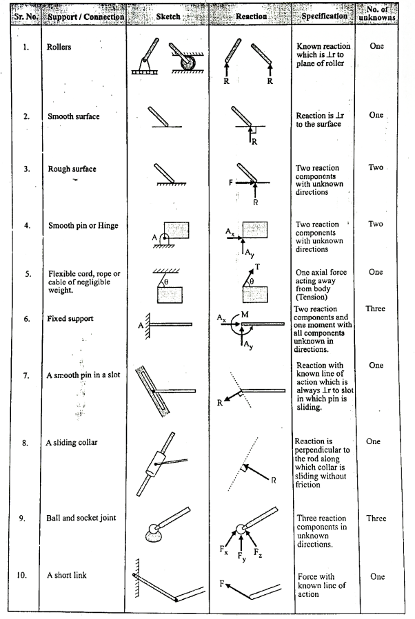
Simple beam and their support reactions are shown in Table below:
Numericals on methods of joints:
Q. Determine the forces in each member of the plane truss as shown in fig. In terms of external loading and state if the members are in tension or compression. Use 
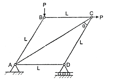
Fig: 15
Soln.:


Ay+RD-100=0
∴Ay=36.6N

Ax=100N
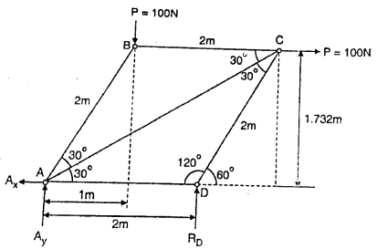
Fig: 16
Consider joint D
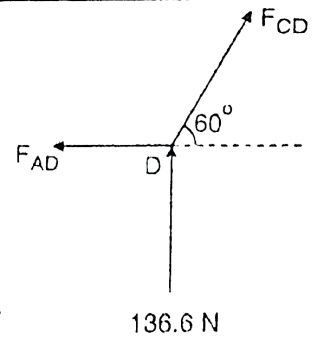
Fig: 17

FCD
∴FCD=-157.73N

FCD

Consider Joint A
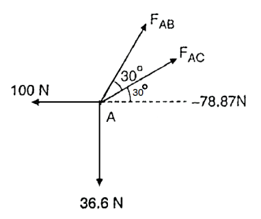
Fig: 18


Consider joint B
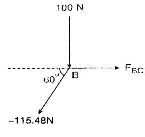
Fig: 19


 =-57.74N
Force table:
Member | AB | BC | CD | AD | AC |
Magnitude | 115.48 | 57.74 | 157.73 | 78.87 | 273.21 |
Nature | C | C | C | C | T |
Q. Determine the axial forces in each member of the plane truss as shown in fig.
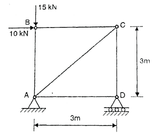
Fig: 20
Soln.: Reactions-


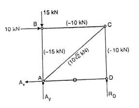
Fig: 21


Joint B: By observation

Joint D: By observation


Joint C
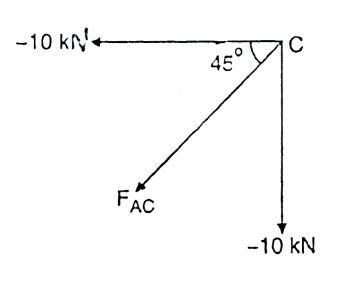
Fig: 22

-

Force Table:
Member | AB | BC | CD | AD | AC |
Magnitude(KN) | 15 | 10 | 10 | 0 |  |
Nature | C | C | C | - | T |
Q. Members AB and BC can support a maximum compressive force of 800N and members AD, DC and BD can support a maximum tensile force of 2000 N. Determine the greatest load P the truss can support.
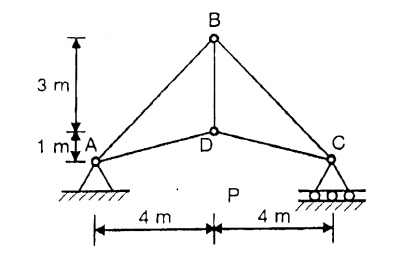
Fig: 23
Soln.:
Consider joint A,
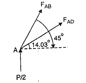
Fig: 24


When
From equation (1) 
From equation (2) P=848.7N
When 
From equation(1) 
So, maximum load P=848.7N
Q. Determine the forces in the members BE and BD of the truss which supports the load as shown in fig. All interior angles are 60 .
.
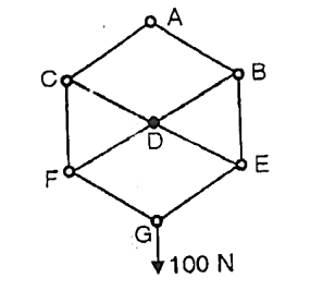
Fig: 25
Soln.:


∴ …(1)
…(1)


∴
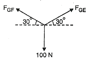
Fig: 26
Consider joint E,
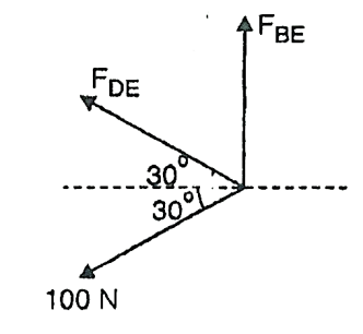
Fig: 27


∴


∴
Consider joint B,
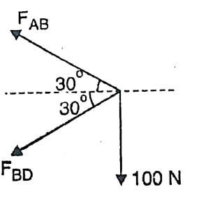
Fig: 28


∴ -
- …(2)
…(2)


∴ …(3)
…(3)
Solving (1) and (2)


Force table:
Member | Magnitude | Nature |
BE | 100N | T |
BD | 100N | C |
Numericals on Method of Sections:
Q. For cantilever truss, find out value of P which would produce the force of magnitude 15kN in member AB.
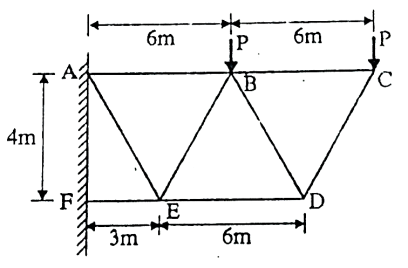
Fig: 29
Soln.:
Step 1: Stability Check
Number of joints J=6
Number of members n=8
Number of reaction components R=4
Checking 2J-R=2(6)-4=8=n
So, truss is perfect.
Step 2: Select a section
Select a section cutting three members AB, BE and DE.
Let F1, F2 and F3 be the tensile forces in members AB,BE and DE respectively.
Step 3: Consider right part and draw F.B.D


Step 4: Conditions of equilibrium:

(F1×4)-P×3-P×9=0
But F1=15KN (Given)
∴15×4=12P
∴P=5KN
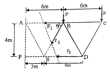
Fig: 30
Q. Determine the force in members FE, FC and BC of the truss using method of sections and state if the members are in tension or compression. Given P1=2.22KN and P2=6.66KN.Refer fig.
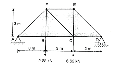
Fig: 31
Sol:
Reaction calculations:
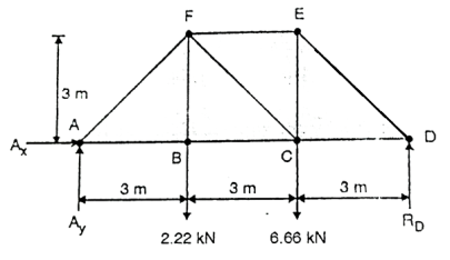
Fig: 32


∴


∴ =3.7KN


Now select as section cutting the member EF.
CF and BC and take F.B.D of right part.
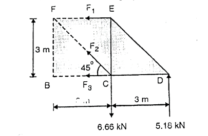
Fig: 33


∴F1=-5.18KN


∴


∴
Sr.No | Member | Magnitude | Nature |
1 | EF | 5.18KN | C |
2 | CF | 2.09KN | T |
3 | BC | 3.7KN | T |
Q. The maximum allowable force (Tension or Compression) in AB,AF and GF is 2.5 KN. Determine the maximum permissible load P on the truss shown in fig.
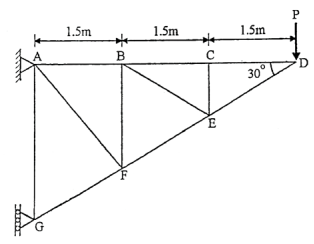
Fig: 34
Sol:
Step 1: Stability check:
Number of joints J=7
Number of members n=11
Number of reaction components R=3
Checking 2J-R=2(7)-3=11=n
So, the truss is perfect.
Step 2:F.B.D of truss and conditions of equilibrium to find out reaction components.
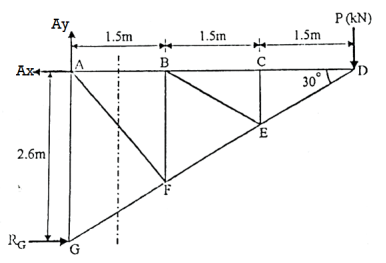
Fig:3.35


∴


∴


∴

∴AG=2.6m
Step 3: Select a section
Select a section cutting members AB,AF and GF and consider F.B.D of right part of the truss.

∴BF=1.732m
Now,

∴
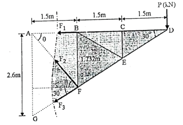
Fig: 36
Step 4: Moment equations


∴ … (1)
… (1)

 (Resolving F3 at G)
∴


∴
Now, it is given in the statement that force in above three members should not exceed 2.5KN.
∴The maximum force in members

∴P=+1.25KN
References:
1. Irving H. Shames (2006), Engineering Mechanics, 4th Edition, Prentice Hall
2. F. P. Beer and E. R. Johnston (2011), Vector Mechanics for Engineers, Vol I - Statics, Vol II, – Dynamics, 9th Ed, Tata McGraw Hill
3. R. C. Hibbler (2006), Engineering Mechanics: Principles of Statics and Dynamics, Pearson Press.
4. Andy Ruina and Rudra Pratap (2011), Introduction to Statics and Dynamics, Oxford University Press
5. Shanes and Rao (2006), Engineering Mechanics, Pearson Education