Unit - 4
Review of particle dynamics
Dynamics is the branch of mechanics that deals with the motion of the particle or a rigid body. In other words, dynamics deals with the accelerated motion of a body. Analysis in dynamics involves motion. Dynamics can be sub-divided into two parts:
Kinematics is the branch of mechanics or simply a part of dynamic analysis which deals with the study or analysis of the motion of the body without considering the forces that causes this motion.
Hence Kinematics only analyses the geometry of the particle or rigid body.
2. Kinetics
Kinetics is the branch of mechanics or simply a part of dynamic analysis which deals with the study of motion of the body by considering the forces that causes this motion.
In other words, kinematics relates with the forces acting on the moving body.
Rectilinear motion:
A particle has a mass but negligible size and shape.
The kinematics of a particle is characterized by specifying, at any given instant, the particle’s position, velocity, and acceleration.
The straight-line path of a particle is defined using a single coordinate axis s, shown in figure below. The origin O on the path is a fixed point, and from this point the position coordinate s specifies the location of the particle at any instant.
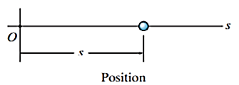
Position is a vector quantity since it has both magnitude and direction
The displacement of the particle is defined as the change in its position. If the particle moves from one point to another, shown in figure below, the displacement is

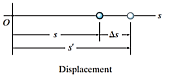
The displacement of a particle is a vector quantity, and it is different from the distance the particle travels. The distance traveled is a positive scalar that represents the total length of path over which the particle travels.
If the particle moves through a displacement  during the time interval
  the average velocity of the particle during this time interval is given by,

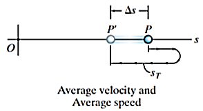
The average speed is always a positive scalar and is defined as the total distance traveled by a particle, sT divided by the elapsed time 

The difference between average speed and velocity is explained in the figure below.
The instantaneous velocity is a vector defined as

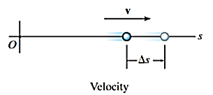
Since dt is always positive, the sign used to define the sense of the velocity is the same as that of displacement.
i.e., if the displacement is in positive direction, then the velocity is positive.
If the velocity of the particle is known at two points, the average acceleration of the particle during the time interval  is defined as

Where, 
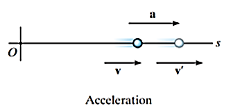
If final velocity of particle is more than the initial velocity, then the acceleration is positive.
Instantaneous acceleration is a vector quantity defined by

If velocity is increasing then acceleration is positive and if it is decreasing then acceleration is negative and referred as deceleration.
If a particle is in a rectilinear motion and displaces displacement of  with initial and final velocity of
  and
and  with the constant acceleration of
  in the time
  , then,


Curvilinear motion occurs when a particle moves along a curved path. Since this path is often described in three dimensions, vector analysis will be used to formulate the particle’s position, velocity, and acceleration.
Consider a particle located at a point on a space curve defined by the path function  , Fig a. The position of the particle is measured from a fixed-point O and is designated by the position vector

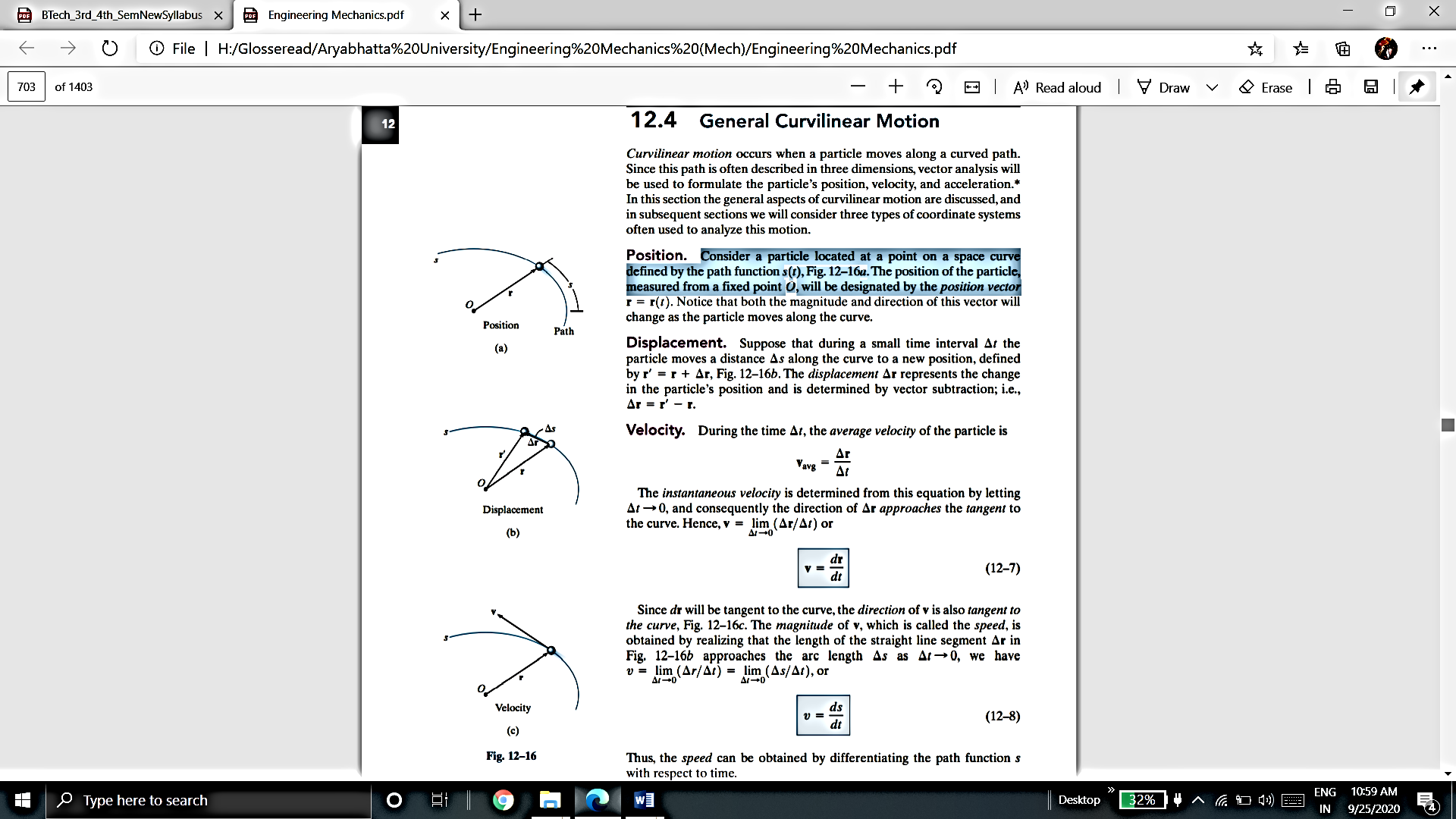
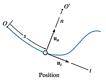
Suppose that during a small-time interval  the particle moves a distance
  along the curve to a new position, defined by

The velocity of particle is a vector quantity defined by first derivative of position vector.

The magnitude of velocity or speed is given by first derivative of path function

The acceleration of a particle is defined by the first derivative of velocity vector.

The magnitude of acceleration is given by second derivative of path function

Plane curvilinear motion: rectangular coordinate
Consider a particle in a motion along the path ‘s’.
The motion of the particle can be best expressed in terms of x and y coordinates.
The position of the particle is defined by the position vector r.

Where, x, y and z are the instantaneous coordinates of the position of particle in motion.
As the particle is in motion, the x, y, z components of r are the function of time.


Hence,

The instantaneous magnitude of the position vector is given by

And the direction of position vector is given by the unit vector

The instantaneous velocity of the particle can be defined by the first derivative of the position vector w.r.t time t


This is the velocity vector
Where,  and
and 
 ,
,  and
and  represents the first derivative of
  and
and  respectively.
The instantaneous magnitude of the velocity can be given as

And the direction of velocity vector is given by the unit vector

Note: The velocity vector is always directed tangent to the path
The acceleration of the particle can be found by first derivative of the velocity vector or second derivative of position vector.


This is the acceleration vector
Where,


 and
and  represents the first-time derivative of
  and
and  (i.e.,
  and
and  ) respectively. Also,
  ,
,  represents the second time derivative of x, y (i.e.,
  ,
,  ) respectively.
The instantaneous magnitude of the acceleration can be given as

And the direction of velocity vector is given by the unit vector

Note: Curvilinear motion can cause changes in both the magnitude and direction of the position, velocity and acceleration vectors.
Plane curvilinear motion: path coordinate
When the path of a particle motion is known, then the motion is best described by n and t coordinate axes that acts normal and tangent to the path of motion of the particle respectively. The origin is considered at the location of particle.
Consider the particle as shown in Figure below.
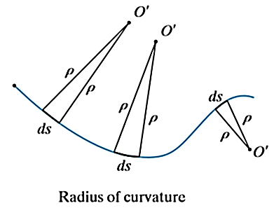
The particle moves in a plane along a fixed curve.
In n-t coordinate system origin is always at the location of the particle.
The t-axis is tangent to the path at the instant in positive direction of the particle’s motion.
The n-axis is perpendicular to the t-axis with the positive direction toward the center of curvature of the curve which is always on the concave side of the curve or path.
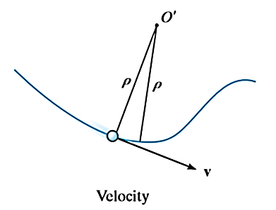
The directions of normal and tangent are defined by the unit vectors 
 and
and 

The position of particle is defined by the distance ‘s’ of the particle from the point O which is fixed on the curve. Generally, it is the start point of the path of particle motion.
S is a function of time and called as path function.

The velocity vector is always tangent to the curve and is given by

The magnitude of velocity is given by

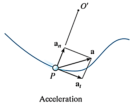
The acceleration of the particle is the time rate of change of the velocity. Thus,

And

Hence,


Where,
 is the tangential component of acceleration while
  is normal component of acceleration. And both are given by,


And

Where,  is the radius of curvature.
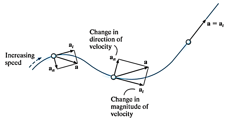
These two mutually perpendicular components of acceleration are shown in Figure above. Therefore, the magnitude of acceleration is given by,

A particle moving along the curved path as shown in Figure below will have accelerations as directed in the figure.
Plane curvilinear motion: polar coordinate
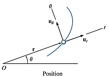
In polar coordinate system, the position of the particle is defined by r and 
Where r is radial coordinate that represents the radial distance and  is the transverse coordinate that represents angle. The directions of the r and
  coordinates are defined by unit vectors
  and
and 
 respectively.
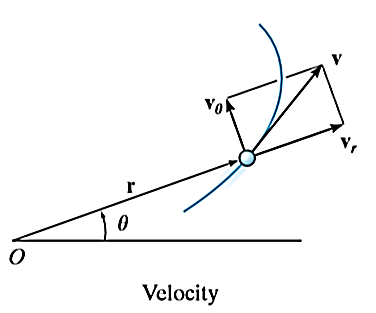
The location of particle at any instant is given by the position vector.

Velocity is given by velocity vector found by first derivative of position vector,

But,

Hence,


Where,

Where, u is the linear instantaneous velocity
And

Where,  is the angular velocity
 is the radial velocity which is due to the change in the displacement or position of the particle.
And  is the transverse velocity which is due to the change in direction of the particle.
Hence, resultant velocity is given by,

The magnitude of the resultant velocity is given by

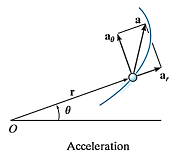
Acceleration of the particle can be found by first derivative of velocity vector


But,

And

Hence,


Where,

And

 is the radial acceleration which is due to the change in the magnitude of velocity of the particle.
And  is the transverse acceleration which is due to the change in direction of velocity of the particle.
The magnitude of resultant acceleration is given by,

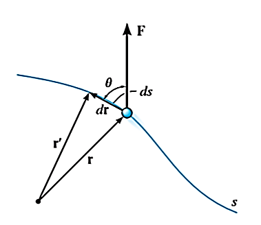
When a particle subjected to force F undergoes a displacement in the direction of the force, the force F will do work on the particle.
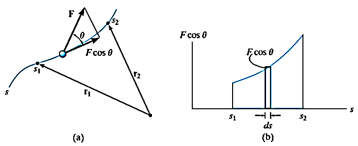
Consider a particle subjected to force F that causes the displacement of ds at an angle of  from the direction of force.
Let,
r = position vector of initial position
r’ = position vector of new position
dr = r’ – r = displacement whose magnitude is ds
The component of forces in the direction of motion that causes the particle to displacement is given as 
As we know,
Work = Force x displacement

Where,  is the work done to displace the particle by ds
The work is a scalar quantity given by the dot product.

There are various types of work for different forces given below:
If a particle is subjected to variable force F that undergoes a displacement along its path with magnitude from  and
and  defined by the position vectors
  and
and  respectively and
  is the angle between the direction of force and the direction of displacement, as shown in figure, then the work done by the force F is given by

Where, F and  are defined as the function of position.

Then the area under this graph bounded by  and
and  represents the total work. (Fig. b)
2. Work of constant force
If a particle is subjected to constant force FC that undergoes a displacement along its path with magnitude from  and
and  defined by the position vectors
  and
and  respectively and
  is the constant angle between the direction of force and the direction of displacement, as shown in figure, then the work done by the force FC is given by


Then the area under this graph bounded by  and
and  (rectangle) represents the total work. (Fig b)
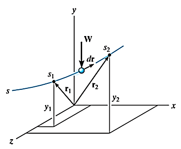
3. Work of weight
Consider a particle of weight W that moves along the path s from the position  to
to  defined by the position vector
  and
and  respectively.
The displacement of a particle at any point intermediate on the path is given by

Since,

We have,


As weight is a constant force, hence,


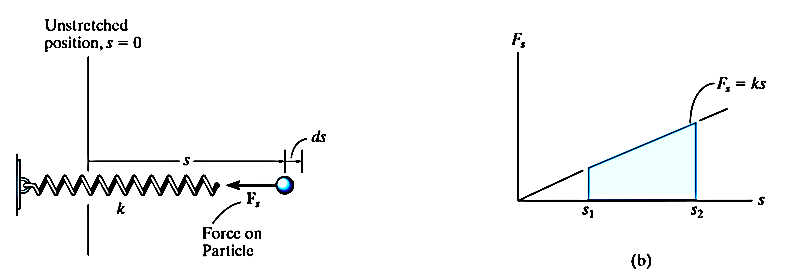
4. Work of spring force
Consider an elastic spring that is elongated by distance ds on the action of force FS as shown below.
If a particle displaces from position  to
to  , then the work done is given by,


The trapezoidal region in the graph represents the total work done.
Principle of Work and Energy
The principle of work and energy states that, sum of the work done by all the forces acting on the particle is equal to the change in total energy (kinetic energy) of the particle.
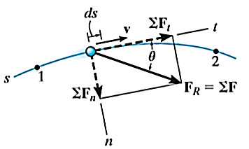
Consider the particle located on the path that is defined relative to an inertial coordinate system as shown in figure below.
Let the particle has initial position  with speed
  and final position
  with speed
Let the particle has a mass m and is subjected to a system of external forces which is represented by the resultant force given below

The equation of motion for the particle in the tangential direction is given by

Applying the kinematic equation  and integrating both sides


Where  and
and  are the initial and final kinetic energies of the particle. Kinetic energy is always positive.
Power is defined as the total amount of work done in a unit time interval.
The power generated by a machine or engine that performs an amount of work dU within the time interval dt is given by,

But, work dU is expressed as 


Where, v represents the velocity of the particle which is acted upon by the force F in the time interval t.
As power is a dot product of force and velocity, it is a scalar quantity.
The term “power” provides a useful basis for choosing the type of motor or machine which is required to do a certain amount of work in a given time. For example, two pumps may each be able to empty a reservoir if given enough time; however, the pump having the larger power will complete the job sooner.
The unit of power is SI system is Watt
1W = 1 J/s = 1 Nm/s
Also, 1 hp = 760 W
The kinetic energy is a measure of the particle’s capacity to do work and is associated with motion of particle. But potential energy is the energy associated with the particle when at rest.
When energy comes from the position of the particle, measured from a fixed datum or reference plane, it is called potential energy. Thus, potential energy is a measure of the amount of work a conservative force will do when it moves from a given position to the datum.
There are two types of potential energy:
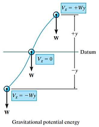
If a particle is located a distance y above an arbitrarily selected datum, as shown in Figure, then weight of particle has positive gravitational potential energy  . Similarly, if a particle is located a distance y below datum, then weight of particle has negative gravitational potential energy
  .
.
And at datum, 
In general, if y is taken positive upward, the gravitational potential energy of the particle of weight W is

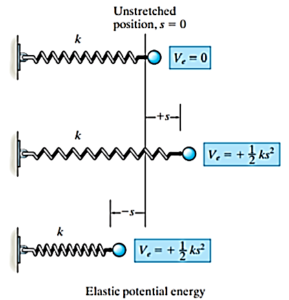
2. Elastic potential energy
When an elastic spring is elongated or compressed a distance s from its unstretched position, elastic potential energy  can be stored in the spring. This energy is given by

Here,  is always positive since, in the deformed position, the force of the spring has the capacity or “potential” for always doing positive work on the particle when the spring is returned to its unstretched position.

Using kinematics, the equation of motion for a particle of m is given by,


Integrating above equation between limits  at
at  to
to  at
at 

The term  is referred as the linear impulse, while the term
  is change in linear momentum.

Since m is a positive scalar, the linear-momentum vector has the same direction as v.
Linear impulse is a vector quantity that measures the effect of a force during the time the force acts. As time is a positive scalar quantity, the impulse acts in the same direction as the force.
If the force is variable, the resulting impulse is given by

If the force is constant in magnitude and also in direction, the resulting impulse is given by


Graphically, magnitude of linear impulse is given by the area under the curve plotted on the force versus time plot.
Now, assume the body is symmetric with respect to an inertial x–y reference plane.
The linear momentum of a rigid body is determined by summing vectorially the linear momenta of all the particles of the body given by

This equation states that the body’s linear momentum is a vector quantity having a magnitude  and direction is defined by the velocity
  of the center of mass of the body
Now, consider the body with mass m, which is subjected to general plane motion with angular velocity  and linear velocity of center of mass given by
  .
.
The angular momentum is given by,

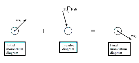
Principle of impulse-momentum states that sum of all the impulses applied to the particle in a time period of motion of a particle is equal to the change in momentum of the particle.
Mathematically,
Initial momentum + sum of impulses = Final momentum
Principle of Linear Impulse and momentum
The equation of translational motion for a rigid body is given as

Since the mass of the body is constant,

Integrating above equation between limits  at
at  to
to  at
at 

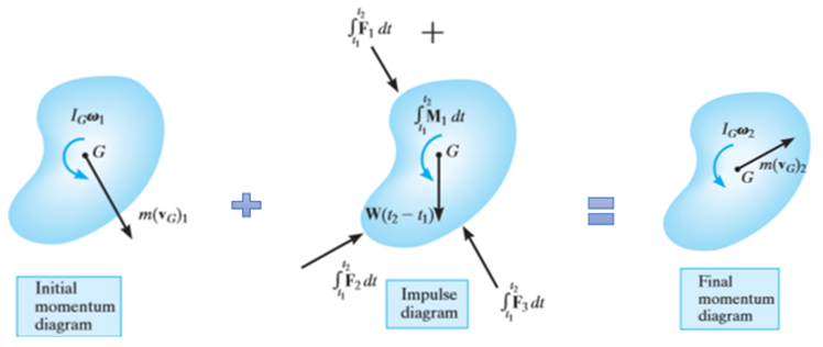
This equation is termed as the principle of linear impulse and momentum. It states that the sum of all the impulses created by the external force system which acts on the body during the time interval  to
to  is equal to the change in the linear momentum of the body during this time interval.
Principle of Angular Impulse and momentum
When the body is a general plane motion,


Integrating above equation between limits  at
at  to
to  at
at 

In a similar manner, for a body in rotation about a fixed axis passing through point O

In general, if motion occurs in the x–y plane, the following three scalar equations can be written to describe the planar motion of the body.


Impact occurs when two bodies collide with each other in a very short period of time, resulting relatively huge (impulsive) forces to be exerted between the bodies.
Example: striking of a hammer on a nail, a golf club on a ball
There are two types on impact:
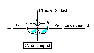
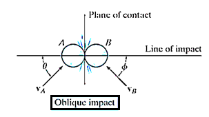
Central impact occurs when the direction of motion of the mass centers of the two colliding particles is along a line passing through the mass centers of the particles. This line is called the line of impact which is perpendicular to plane of contact.
2. Oblique impact
When the motion of one or both of the particles make an angle with the line of impact, then the impact is said to be oblique impact.
Central impact:
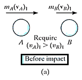
Consider two particles A and B involving the central impact of the shown in Fig. a
Let velocity of particle A is more than particle B.
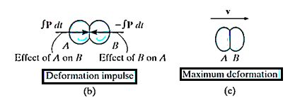
During the collision the particles must be considered as deformable or nonrigid particles. The particles will undergo a period of deformation such that they exert an equal but opposite deformation impulse  on each other.
When the deformation becomes maximum, the relative motion of particle will become zero. Hence, the particle will move with same velocity v.
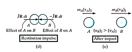
Then the particles will either return to their original shape or remain permanently deformed. This occurs after the period of restitution.
The equal but opposite restitution impulse  pushes the particles apart from each another, shown in fig d. In reality, the physical properties of any two bodies are such that the deformation impulse will always be greater than that of restitution.

After the separation, the particles will have the final momenta as shown in Fig e.
Momentum for the system of particles is conserved as during the collision the internal impulses of deformation and restitution cancel each other.
Hence,

Applying impulse momentum equation for particle A during deformation phase (fig a, b and c), we get


Now, applying impulse momentum equation for particle A during restitution phase (fig c, d and e), we get


The ratio of the restitution impulse to the deformation impulse is called the coefficient of restitution.

Similarly, Coefficient of restitution can be established for particle B.

If velocity  is unknown, then it can be eliminated from above equations and coefficient of restitution can be expressed in terms of the particle’s initial and final velocities

When, e = 1, the collision between the two particles is perfectly elastic. In perfectly elastic collision, the deformation impulse is equal and opposite to the restitution impulse. This is the ideal case and is impossible to achieve this case.
When e = 0, the collision between the two particles is perfectly plastic. In this case there is no restitution impulse so that after collision both particles couple or stick together and move with a common velocity.
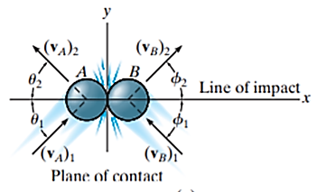
Oblique impact:
When oblique impact occurs between two smooth particles, the particles move away from each other with velocities having unknown directions as well as unknown magnitudes. Provided the initial velocities are known, then four unknowns are present in the problem.
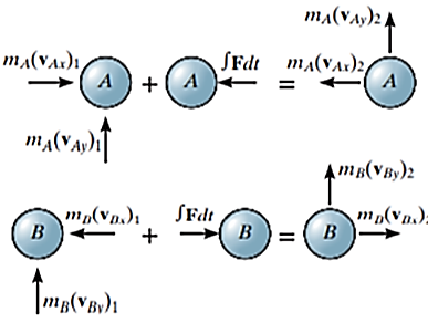
As shown in Figure, these unknowns may be represented either as  ,
,  ,
,  and
and  or the x and y components of final velocities.
References:
1. Irving H. Shames (2006), Engineering Mechanics, 4th Edition, Prentice Hall
2. F. P. Beer and E. R. Johnston (2011), Vector Mechanics for Engineers, Vol I - Statics, Vol II, – Dynamics, 9th Ed, Tata McGraw Hill
3. R. C. Hibbler (2006), Engineering Mechanics: Principles of Statics and Dynamics, Pearson Press.
4. Andy Ruina and Rudra Pratap (2011), Introduction to Statics and Dynamics, Oxford University Press
5. Shanes and Rao (2006), Engineering Mechanics, Pearson Education