Unit - 1
Fluid and Continuum
- Any substance which is capable to flow is called as fluid.
- Fluid is a substance that deform continuously under the action of shear stress, no matter if it is small.
- It has no definite shape of its own, but confirms to the shape of the container.
- Fluid consists of liquid and gases.
Example of fluids:
- Breathing, drinking, blood circulation in the human body. Fluid is everywhere, in the ocean, in the atmosphere and around the aircraft or a missile etc.
Classification of Fluids:
There are two types of fluids:
- Liquid and Gases
- Ideal fluid and Real Fluid
1. Liquid and Gases
Liquid:
- Fluids, which are not able to compress, but possess a deficit volume, which are not affected appreciably by the change in pressure and temperature is called as liquid. e.g., Water, Kerosene, Petrol etc.
- A liquid being composed of relatively closed-packed molecules with strong cohesive forces tends to retain its volume and will form a free surface in gravitational field or in container as shown in Fig.
Gases:
- A fluid which are compressible and possess no definite volume, it is compressed or expands at any change in temperature is called as gases. e.g., Air, Ammonia, CO, etc.
- Gas molecules are widely spaced with negligible cohesive forces, so that it is free to expand until it encounters confining walls as shown in Fig.
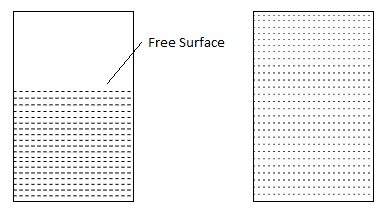
Fig.1: Liquid and Gases resp.
2. Ideal fluid and Real Fluid:
Ideal fluid-
- Fluids which have no viscosity and surface tension and those are incompressible is called as ideal fluid. Ideal fluids are an imaginary fluid and do not exist in the nature.
- As water is incompressible, it is considered as an ideal fluid.
Real fluid-
- Fluids which possess the properties like viscosity, surface tension and compressibility is called as real or practical fluid.
- Whenever the motion takes place, the tangential or shears force is always offered by the fluid.
Fluid Mechanics:
- The fluid mechanics is the branch of engineering science, which deals with the behavior of fluids either in rest or in motion.
Fluid Statics:
- The study of mechanics of fluids at absolute and relative rest is called as fluid statics. Shear stress is always zero in fluid statics.
Fluid Dynamics:
- The study of mechanics of fluids in motion is called as fluid dynamics. Fluids sustain some shear forces. e.g., flow through pipes, channel etc.
Fluid Kinematics:
- Fluid kinematics deals with translation, rotation and deformation of the fluid element without considering the force and energy causing such a motion.
- It deals with the velocities, acceleration and the flow patterns only. It does not consider force or energy that produced the velocity or acceleration in the fluid.
Fluid Kinetics:
- Fluid kinetics is deals with the relation between velocities and acceleration and the forces, which are exerted by or upon the moving fluids.
Application / Necessity of Fluid Mechanics:
- The flight of birds in the air and the motion of the fish in the water are governed by the law of fluid mechanics.
- The cricket ball bowling depends upon circulation principle to provide the ball with desired spin and flight.
- The circulation of blood in veins and arteries follows the law of fluid resistance.
- The design of aeroplanes and ships are based on the theory of aerodynamics and buoyancy.
- The oil and gas pipelines, the water supply systems are designed on the principles of fluid mechanics.
Key Takeaways:
Any substance which is capable to flow is called as fluid. Fluid is a substance that deform continuously under the action of shear stress, no matter if it is small. It has no definite shape of its own, but confirms to the shape of the container. Fluid consists of liquid and gases.
- A continuous distribution of matter with no voids or empty spaces is called as continuum. For mechanical analysis, a fluid is considered to be continuum. e.g., water flowing through pipes, channel.
- Continuum is based on assumption that fluid is continuous. That is the properties such as density, pressure, temperature and velocity are taken to be well defined at infinitely small points and are assumed to vary continuously from one point to another. Air is considered as a Continuum.
- The mean-free-path-of atmospheric air is about 5 - 7.5 x 10⁻⁶ cm but this molecular spacing increases even under lower pressure, and the air no longer remains a continuum.
Key Takeaways:
A continuous distribution of matter with no voids or empty spaces is called as continuum. For mechanical analysis, a fluid is considered to be continuum. e.g., water flowing through pipes, channel.
Physical properties of fluid are as follows:
- Density or Mass Density
- Weight Density or Specific Weight or Unit Density
- Specific Volume
- Specific Gravity or Relative Density
1.Density or Mass Density:
- The density of a fluid is defined as the mass per unit volume.
- It is denoted by 'p' (rho). S.I. Unit is kg/m³.
- Mass density of water is 1000kg/m³.
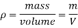
2.Weight Density or Specific Weight or Unit Density:
- The specific weight of a fluid is defined as weight per unit volume at a standard temperature and pressure.
- It is denoted by 'w' or 'y' (gamma). It has S.1. Unit is N/m. Specific weight of water is 9810 Nin (9.81 kN/m).
∴
- The specific weight depends on gravitational acceleration and the mass density. Since gravitational attraction varies from place to place, the specific weight will also vary.
3. Specific Volume
- Specific volume of a liquid is the volume of the fluid per unit weight. It is the reciprocal of specific weight.
- It is denoted by 'V'. S.I. Unit is m3/N.
Vs= =
= =
= in case of liquid
- For the gas flow, specific volume is defined as the volume of the fluid per unit mass. In this case it is a reciprocal of mass density. S.I. Unit is m3/kg.
Vs= =
= =
= in case of gas
4. Specific Gravity or Relative Density
- Specific gravity is the ratio of specific weight (or mass density) of fluid to the specific weight (or mass density) of a standard fluid.
- It is denoted by S or RD.
- Specific gravity =

- For liquid, water and for gases, hydrogen or air is consider as a standard fluid.
- Specific gravity of water at a standard temperature 4°C is 1 and that of mercury is 13.6.
Key Takeaways:
Physical properties of fluid are as follows:
- Density or Mass Density
- Weight Density or Specific Weight or Unit Density
- Specific Volume
- Specific Gravity or Relative Density
- Rheology is the have a look at of the glide of count number, mostly in a liquid or fueloline state, however additionally as "smooth solids" or solids below situations wherein they reply with plastic glide as opposed to deforming elastically in reaction to a carried-out force.
- Rheology is a department of physics, and it's far the technology that offers with the deformation and glide of substances, each solid and drinks.
- The time period rheology became coined with the aid of using Eugene C. Bingham, a professor at Lafayette College, in 1920, from an offer with the aid of using a colleague, Markus Reiner.
- The time period became stimulated with the aid of using the aphorism of Simplicius (regularly attributed to Heraclitus), panta rhei 'the whole lot flows', and became first used to explain the glide of drinks and the deformation of solids.
- It applies to materials which have a complicated microstructure, together with muds, sludges, suspensions, polymers and different glass formers (e.g., silicates), in addition to many meals and additives, physical fluids (e.g., blood) and different organic substances, and different substances that belong to the magnificence of smooth count number together with food.
- Newtonian fluids may be characterized with the aid of using an unmarried coefficient of viscosity for a particular temperature.
- Although this viscosity will alternate with temperature, it does now no longer alternate with the stress price.
- Only a small institution of fluids showcases such regular viscosity. The big magnificence of fluids whose viscosity modifications with the stress price (the relative glide pace) are known as non-Newtonian fluids.
- Rheology usually money owed for the conduct of non-Newtonian fluids, with the aid of using characterizing the minimal wide variety of features which can be wanted to narrate stresses with price of alternate of stress or stress rates.
Key Takeaways:
Rheology is the have a look at of the glide of count number, mostly in a liquid or fueloline state, however additionally as "smooth solids" or solids below situations wherein they reply with plastic glide as opposed to deforming elastically in reaction to a carried-out force.
The relationship between pressure, density and height is as follows:
P=
Where,  Density
Z= Acceleration
U-Tube Manometer:
- Piezometer cannot be employed when large pressures in the lighter liquids are to be measured, since this would require very long tubes, which cannot be handled conveniently.
- Furthermore, gas pressures cannot be measured by piezometer because a gas forms no free atmospheric surface.
- These limitations can be overcome by the use of U-tube manometers.
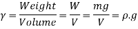
- A U-tube manometer consists of a glass tube but in U-shape, one end of which is connected to a point at which pressure is to be measured and other end remains open to the atmosphere as shown in fig.
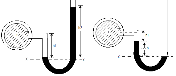
Fig 2: U-tube manometer
Let A be the point at which pressure is to be measured. X-X is the datum line as shown in Fig(a)
Let, h1 = height of the light liquid in the left limb above the datum line
h2 = height of the heavy liquid in the right limb above the datum line
h = pressure in pipe, expressed in terms of head
S1 = specific gravity of the light liquid, and
S2 = specific gravity of the heavy liquid
The pressure in the left limb and right limb above the datum line X-X are equal.
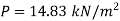
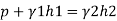
Pressure head above X-X line in the left limb = h+h1S1
Pressure head above X-X in the right limb = h2S2
Equating these two pressures, we get
For negative pressure:
Refer to fig(b)
Pressure head above x-x in the left limb=
Pressure head above x-x in the right limb = 0
Equating these two pressures, we get
h + h1S1 + h2S2 = 0 or h = - h2S2 - h1S1
Examples:
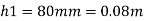
Q.A simple U-tube manometer is used to measure water pressure in pipe line. The left limb of manometer connected to the pipe and the night limb is open to atmosphere. The mercury level in the left limb is 80mm below the center of the pipe and the level in the right limb in 220mm above the center of the pipe. Calculate the pressure of water in meter and also in km .
Soln.:
Oil
Mercury

Fig: 3

Pressure in the left limb about xx = Pressure in the right limb about x-s

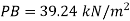
Q.A U-tube manometer is used to measure the pressure of water in a pipe line, which is in excess of atmospheric pressure. The night limb of the manometer contains mercury and is open to atmosphere. The contact between water and mercury is in the left limb. Determine the pressure of water in the main line, if the difference in level of mercury in the limbs of U-tule 12 cm and the free surface of mercury is in level with the centre of the pipe. It the pressure of water in pipe he is reduced to 9810 N/m². Calculate the new difference in the level of mercury.
Soln.:
Fig:4
Case I:
Given:
h1, =h₂= 12cm=0.12 m.
S2=13.6
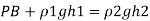
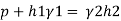
Pressure in pipe

Case II:
Since the pressure in the pipe is reduced to 9.81 kN/m² (which is less than 14.83 kN/m²), the mercury in the left limp will be rise. Rise of mercury in the left limb will be equal to the fall of mercury in right limb as the total volume of mercury remains same.
Let x = rise of mercury in left limb= fall in mercury in right limb,
Pressure at new section x₁ - x₁


New difference of mercury

Q. Fig. P shows a conical vessel having its outlet at A to which a U-tube manometer is connected. The reading of the manometer given in the Fig. P. 3.7.15 shows when the vessel is empty. Find the reading of the manometer when the vessel is completely filled with water.
Soln.:
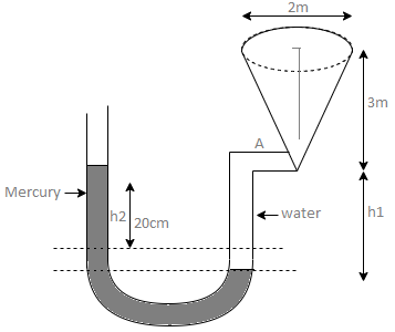
Fig: 5
Case I:
Vessel is empty
Pressure in left limb about x-x= Pressure in right limb about x-x

Case II: Vessel is full of water
When pressure is full of water, the pressure in right limb will increase and mercury level will fall by 'y' m, similarly Hg level in left limb will rise by 'y' m
Now consider 7-7 as a datum
Pressure in left limb = Pressure in right limb about z-z


:. Difference of mercury level when the vessel is full of

Key takeaways:
- Piezometer cannot be employed when large pressures in the lighter liquids are to be measured, since this would require very long tubes, which cannot be handled conveniently.
- Furthermore, gas pressures cannot be measured by piezometer because a gas forms no free atmospheric surface.
- These limitations can be overcome by the use of U-tube manometers.
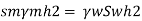
Single Column Manometer:
This type of manometer is useful for the measurement of small pressures and is more sensitive than the vertical tube type.
Due to inclination the distance moved by the heavy liquid in the right limb is more.
l = length of the heavy liquid moved in right limb,
Alpha = inclination of right limb horizontal, and
h2 = vertical rise of liquid in right limb from x-x = l sin
h = l sin alpha × S2 - h1S1
Fig. 6: Single column manometer
Key takeaways
- This type of manometer is useful for the measurement of small pressures and is more sensitive than the vertical tube type.
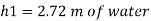
U-Tube Differential Manometer:
A U-tube differential manometer is shown in fig.
Fig. 7: U tube differential manometer
Let, h = difference of mercury level (heavy liquid) in the U-tube,
h1 = distance of the centre of A, from the mercury level in the left limb
h2 = distance of the centre of B, from the mercury level in the right limb,
S1 = specific gravity of liquid in pipe A,
S2 = specific gravity of liquid in pipe B,
S = specific gravity of heavy liquid o mercury
HA = pressure head at A,
HB = pressure head at B
Considering the pressure heads above the datum line x-x, we get
Pressure head in the left limb:
h A + (h 1 + h) S1
Pressure head in the right limb:
h B + h 2 × S 2 + h × S
Equating the above pressure heads, we get
h A + (h1 + h) S1 = h B + h 2 × S 2 + h× S
(h A - h B) = h 2 × S 2 + h × S - (h 1 + h) S 1
Examples:
Q.A differential manometer is connected at two points A and B of two pipes as shown in Fig. Pipe A contains liquid of specific gravity 1.6, while pipe B contains liquid of specific gravity 0.8. If the pressure at A and B are 11.80 x 10 N/m² and 19.60 x 10 N/m2, find the difference in mercury level in the differential manometer.
Soln.:
Pipe A
S₁ = 1.6
PA = 11.8 x 10' N/m² = 118 kN/m² 19.62× 10¹ N/m² = 196.2 kN/m²
h₁ = (2+1,5) = 3.5 h₂ = (1.5 + h)
Pipe B
s2= 0.8
h2= 1.5+h
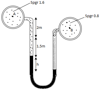
Fig:8
Pressure in left limb = pressure in right limb PA

Q.A U-tube manometer (Fig. P.) measures the pressure difference between two points A and B in a liquid of density PL The U tube contains mercury of density pa. Calculate the difference of pressure between points A and B in a liquid of density p, The u tube contains mercury of density P Calculate the difference of pressure between points A and B if the liquid contain at A is water take a 1.5 m, b=0.75 m and h= 0.50 m.
Soln.:
Given:


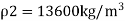

To find:
PA-PB
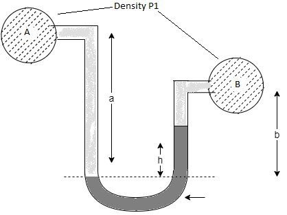
Fig: 9
Pressure in left limb = Pressure in right limb


Q. Liquid of specific gravity 1.0 flows through pipes A and B at positive pressures of 0.5 bar and 0.25 bar respectively. Pipe A is 1.8 m higher than B. What would be the difference in the levels of U-tube manometer connected to A and B, having manometric liquid of specific gravity 13.6? Liquid level in the limb attached to A is lower than that in the order.
Soln.:
Given:
Fig: 10
1 1bar = 10^5 N/m²,
2 P=0.5 bar = 50 kN/m².
3 pB= 0.25 bar 25 kN/m²
Balancing the liquid about x-x in left limb and right limb
Pressure in left limb about x-x= Pressure in right limb about x-x


Key takeaways
- The final equation to calculate pressure from u tube manometer is
(h A - h B) = h 2 × S 2 + h × S - (h 1 + h) S 1
Micromanometers:
- A micro manometer can be used - if required in combination with pitot tubes - to measure, measure, measure and calculate velocity and volumetric flow rate. Micro manometers have high accuracy for measuring high-, low- and variability. Observatory Instruments offer different micro manometers, each with a different application.
- One leg of the micro manometer is the source and the other is the inclined tube, which contains a magnifier. The meniscus in the inclined tube is located at a reliable level adjusted by the hairline viewed by the magnifier.
- First of all, both the source and the amplifier are the same pressure. The application of pressure at the end of the spring removes the hairline but can be restored to its original position by increasing or lowering the source (mercury sump).
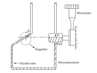
Fig. 11: Micromanometer
Key takeaways:
A micro manometer can be used - if required in combination with pitot tubes - to measure, measure, measure and calculate velocity and volumetric flow rate. Micro manometers have high accuracy for measuring high-, low- and variability. Observatory Instruments offer different micro manometers, each with a different application.
Pressure on Plane surface:
A pressure diagram is the graphical representation of the variation in the intensity of pressure over a surface. It is used to calculate total pressure force and centre of pressure for submerged body.
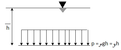
Fig.12: Pressure diagram for horizontal surface
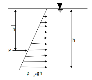
Fig.13: Pressure diagram for vertical surface
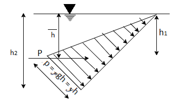
Fig.14: Pressure diagram for inclined surface
Centre of pressure by principle of moment,
P =
= +P2
+P2 +P3
+P3
Pressure on Curved Surface:
Consider a completely submerged curve surface under water. Consider an elementary area dA situated at a depth 'h' below free water surface. As shown in Fig.
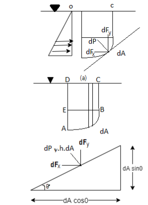
Fig:15
Total pressure acting on elementary area (dA)
DP =  hdA
hdA
Total pressure,

Total Pressure,
 ∴P=
∴P=
But in case of curved surface, the direction of the total pressure on the elementary area is not in the same direction, but varies from point to point. Thus, the integration of Equation for curved surface is impossible. So that this problem will be solve by resolving the force P into horizontal and vertical components PH and Py
Then total force on the curved surface is,
P =
Direction of Resultant force,
 =
= 
Horizontal Component,
 =
=
∴ = The total pressure force on the projected area of the curved surface on the vertical plane.
∴PH = The total pressure force on the projected area of the curved surface on the vertical plane.
Vertical components,
 =
=
∴ = Vertical projected area of the curve surface as shown in Fig
∴Now dA = Horizontal projected area of the curve surface as shown in Fig.
∴ = Total volume of liquid contained between curved surface and free surface.
∴ = = Total weight of liquid contained between curved surface and free surface.
 = Total weight of liquid contained between curved surface and free surface.
The point at which the total pressure is supposed to be act is called as centre of pressure. It is denoted by 
 =
= +
+
- The tendency of fluid to uplift a submerged body, due to the upward thrust of the fluid is known as buoyancy or force of buoyancy.
- It is always equal to the weight of fluid displaced by the body.
Centre of Buoyancy:
- The point at which the force of buoyancy is act is called as centre of buoyancy.
- It always lies C.G. Of the volume of the liquid displaced.
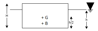
Fig.16: Center of Buoyancy
Where, H is the height of body. h is submerged height of block i.e., depth of immersion.
Key Takeaways:
The tendency of fluid to uplift a submerged body, due to the upward thrust of the fluid is known as buoyancy or force of buoyancy. It is always equal to the weight of fluid displaced by the body.
Stability of floating bodies:
(1) Stable equilibrium
- When a body is given a smaller angular displacement due to external force and then it comes to its original position due to internal forces, is called as stable equilibrium.
- In stable equilibrium, metacentre is lies above centre of gravity, the metacentric height is positive.
- External couple is balanced by couple due to internal force.
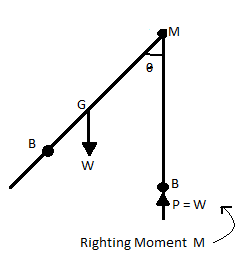
Fig.17: Stable equilibrium
(2) Unstable equilibrium
- When a body does not return to its original position from the slightly displaced angular position and heels farther away, is callesi.us unstable equilibrium.
- In unstable equilibrium, metacentre M is lies below the centre of gravity G, the metacentre height is negative.
- External couple and couple due to internal force are in same direction. It is an unstable condition.
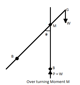
Fig. 18: Unstable equilibrium
(3) Neutral equilibrium
- When a body is given a smaller angular displacement and set on new position, is called as neutral equilibrium.
- In neutral equilibrium, metacentre M and centre of gravity G are coincided.
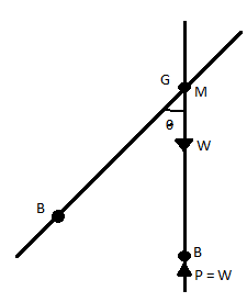
Fig. 19: Neutral equilibrium
Stability of immersed bodies:
Condition of stability for submerged body are based on relative positions of centre of gravity G and centre of buoyancy B.
(1) Stable equilibrium
- When centre of buoyancy is lies above the centre of gravity. Submerged body is stable.
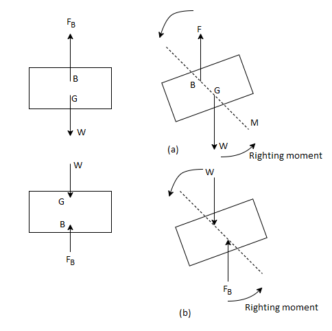
Fig: 20
(2) Unstable equilibrium:
- When centre of buoyancy is lies below centre of gravity, submerged body is in unstable equilibrium.
(3) Neutral equilibrium:
- When centre of buoyancy and centre of gravity is coincided, body is in neutral equilibrium.
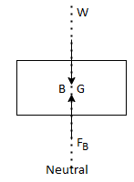
Fig: 21
Key Takeaways:
The three types of equilibrium are given in both case:
- Stable equilibrium,
- Unstable equilibrium
- Neutral equilibrium
Fluid Mass Subjected to Linear Acceleration:
- Consider a tank filled with liquid actions toward the proper aspect with a uniform acceleration.
- As the tank stats shifting below the movement of acceleration pressure, the liquid does now no longer stay in horizontal level.
- The liquid floor falls down at the route of movement and upward push up at the returned aspect of the lank.
- Consider the equilibrium of a fluid particle A mendacity at the willing unfastened floor as proven in.
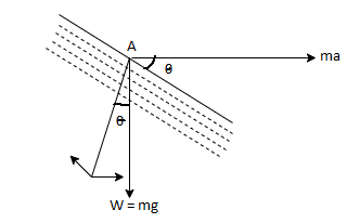
Fig: 22
- The pressure performing at the liquid particle are weight of the particle W = mg performing vertically downwards, accelerating pressure F performing in the direction of proper and ordinary stress P exerted through the liquid.
Acceleration pressure F = ma
Resolving horizontally P sin θ = F = ma
Resolving vertically P cos θ = W = mg
Dividing Equation (i) to (ii)
P sin θ / P cos θ = ma / mg = a/g
Tan θ = a/g
- Now keep in mind the equilibrium of the complete mass of the liquid. Let P1 and P2 are the hydrostatic stress at the returned aspect and the front aspect of the tank.
Net pressure P = P1- P2
By Newton’s 2d regulation of movement,
P = ma
(P1-P2) = ma
- Since the inclination θ of liquid floor stays steady all of the factors at the liquid floor, consequently the liquid floor will be predisposed at a steady perspective θ with the horizontal.
- The inclination of the liquid floor is at once proportional to the horizontal acceleration.
- The gasoline tank on an aircraft at some point of take-off is the great example.
References:
1.Hibbler, “Fluid Mechanics in SI units”1/e Pearson Education, Noida
2.Cengel & Cimbala, “Fluid mechanics” TMH, New Delhi
3.Katz, “Introductory Fluid Mechanics” Cambridge University Press
4.Pnueli & Gutfinger, “Fluid Mechanics” Cambridge University Press
5.Modi & Seth “Hydraulics & Fluid Mechanics” Standard Publication


