Unit - 3
Potential Flow
- Potential flow is an idealized model of fluid flow that occurs in the case of incompressible, inviscid, and irrotational flow.
- The velocity potential of a potential flow satisfies Laplace's equation:
∇2ϕ⃗ =0.
Source and sink:
- A radially symmetrical flow field directed outwards from a common point is called source flow.
- Sink flow is opposite to the source flow.
Doublet:
- A Particular case of Dipole is called as Doublet.
Consider steady flow of an ideal fluid along the shown tube.
Separate out a small element of fluid of cross- sectional area dA and length ds from stream tube as a free body from the during fluid.
Fig. Shows such a small elements LM of fluid of cross Section area dA and length ds.
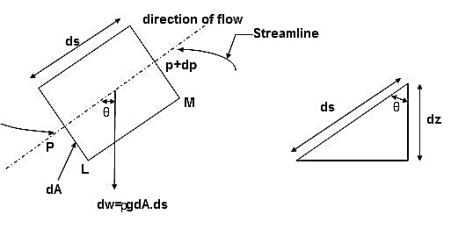
Fig. 1: Equation of motion Diagram
Let, p= Pressure of the elements at L
p + dp = Pressure on the element at M, and
V=Velocity of the fluid element.
The external forces tending to accelerate the fluid elements in the direction of streamline are as follows:
Net pressure force in the direction of flows is, p.dA – (p+dp)dA = -dp. DA
Component of the weight of the fluid elements in the direction of flows is
= - .g.dA.ds.cos
=-  .g.dA.ds (dz/ds) (:. Cos = dz/ds)
= -  .g.dA.dz
Mass flow of the fluid element =  .dA.ds
The Acceleration of the fluid element,
a = dv/dt = dv/ds * ds/dt = v. Dv/ds
Now, according to Newton’s second law of motion, force= mass x acceleration.
∴ – dp. DA.-  .g.dA.dz=
 .dA.ds x v.dv/ds
Dividing both sides by rho .dA, we get
-dp/- . g.dz= v.dv
Or dp/ + v.dv + g.dz=0
This is the required Euler’s equation for motion.
Integrating the Euler’s equation of motion we get
1/ ∫ d p +∫v. d v+ ∫g.dz=constant
p/ ρ + v2 /2 + g z = constant
Dividing by g, we get
p/  g + v 2/2g + z = constant
p /w + v 2/2g + z = constant
Or in other words, P1/ W+V1 2 / 2 g +Z1=P2/ W+V22 / 2g+Z2
Which proves Bernoulli’s equation.
Key takeaways
Euler equation is given as -
P1/ W+V1 2 / 2 g +Z1=P2/ W+V22 / 2g+Z2
Assumptions made in Bernoulli’s equation.
- The liquid is ideal & incompressible.
- The flow is steady & continuous.
- The flow is along stream line.
- The velocity is uniform over the section & equal to mean velocity.
- Only forces acting on the fluid are the gravity forces & pressure forces.
Bernoulli equation :
- Bernoulli’s equation is based on Euler’s theory of the fluid flow and it obtained by integrating the Euler’s equation of motion.
. +gdz+dv=0
Integrating, +
+ +
+
For incompressible flow , is constant.
∴  +gz+
+gz+ =constant
 +z+
+z+ =constant
This equation is called as Bernoulli’s Equation
Applications of Bernoulli’s equation
Bernoulli’s equation is applied is all problems of incompressible fluid flow where energy considerations are involved, But we shall consider its applications to the following measuring devices:
- Venturimeter
- Pitot- tube
- Sub-merged orifice
- Orifice meters
- Rotameter.
Limitation of Bernoulli’s equation
- Velocity of every liquid particle, across any section of pipe is not uniform.
- Bernoulli’s equation is not applicable for fluid with unsteady flow.
- If fluid flowing in a curved path, the energy due to centrifugal force should be taken into account.
- It is a device used for measuring the velocity of flow at any point in a pipe or a channel.
- It is based on the principle, that if the velocity of flow at a point becomes zero, the pressure there is increased due to the conservation of the kinetic energy into pressure energy.
- In its simplest form, the pitot- tube consists of a glass tube, bent at right angles as shown in fig.
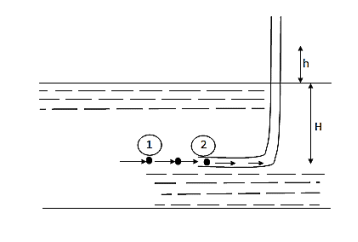
Fig. 2: Pitot tubes
- The Lower end, which is bent though 90° is directed in the upstream direction as shown in fig.
- The liquid rises up in the tube due to the conservation of kinetic energy into pressure energy.
- The velocity is determined by measuring the rise of liquid in the tube.
P1= intensity of pressure at point (1)
V1 = velocity of flow at (1)
P2 = pressure at point (2)
V2 = velocity at point (2), which is zero
H = depth of tube in the liquid.
h = rise of liquid in the tube above the fire Surface
Applying Bernoulli’s equation at points (1) and (2)
We get
P1/ W+V1 2 / 2 g +Z1=P2/ W+V22 / 2g+Z2
But Z 1 = Z2as points (1) and (2) are the same line and V2 =0
P1 /g= pressure Lead at (1) = H
P2 /g = pressure head at (2) = (h +H)
Substituting these values, we get
H+ V1 2 / 2 g = (h+H)
:. h= V1 2 / 2 g or v 1 =  (2 g h)
This is theoretical velocity.
Actual velocity is gives by (V 1) = Cv (2 g h)
Where C v= Co-efficient of pitot-tube
:. Velocity at any point V= Cv (2 g h)
- It is a device used for measuring the rate of flow of a fluid through a pipe.
- It is a cheaper device compared to venturimeter
- It also works on the same principle as that of venturimeters.
- It consists of a flat circle plate which has a circular shape edged holed called orifice, which is concentric with the pipe.
- The orifice diameter is kept generally 0.5 times the diameters of the pipe, though it may vary from 0.4 to 0.8 times the pipe diameters.
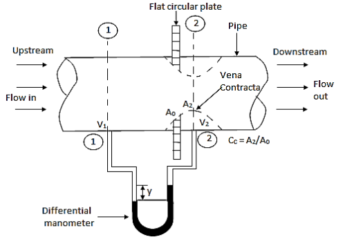
Fig. 3: Orifice meter
A differential manometer is connected at section
- Which is at a distance of about 1.5 to 2.0 times the pipe diameters upstream from the orifice plate, and at section
- Which is at a distance of about half the diameters of the orifice on the downstream side from the orifice plate.
A venturi meter is a device used for measuring the rate of a flow of a fluid flowing through a pipe it consists of three parts:
- A short converging part,
- Throat, and
- Diverging Part
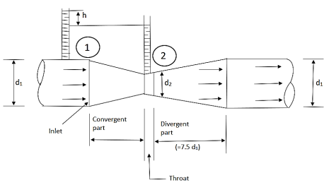
Fig. 4: Venturimeter
It is based on the principle of Bernoulli’s equation.
Expression for Rate of flow through venturimeter:
Consider a venturimeter fitted in a horizontal pipe through which a fluid is following as shown in fig.
Let d 1 = diameter at inlet or at section (1)
P 1= pressure at section (1)
V 1= velocity of fluid at section (1)
A 1= area of section (1) =π/4. D2
And d 2, P 2, V 2, a 2 are corresponding values at section (2)
Applying Bernoulli’s equation at section (1) and (2) we get
P1/  g+V12 /2g+Z1=P2 /
  g+V22 /2g+Z2
As pipe is horizontal hence z 1 = z2
P1/  g+V12 /2g =P2 /
  g+V22 /2g
(P1 – p 2)/  g = V22 /2g - V12 /2g
But (P1 – p 2)/  g is the difference of pressure heads at section land 2 and it is equal to h
∴ (P1 – p 2)/  g =h
g =h
Substituting this value of (P1 – p 2)/  g in the above eqn we get.
∴ h = V22 /2g - V12 /2g………….. (1)
Now applying continuity equation at section 1 and
a 1 v 1 = a 2 v 2
∴ v 1 = a 2 v 2 / a 1
Substituting this value of v 1 in equation 1
h= V22 /2g – (a 2 v 2 / a 1) 2 / 2 g
h= V22 /2g [ (a 12 –a 22 )/ a 12 ]
V22 = (2 g h a 12 )/ (a 12 –a 22)
Q = a2 v 2
= [a 1 a 2 /  ( a 12 –a 22 ) ] *
  ( 2 g h ) ]
Above equation gives the discharge under ideal conditions and is called, Theoretical discharge Actual discharge will be less than theoretical discharge.
Q act = C d * [a 1 a 2 /  ( a 12 –a 22)] *
  (2 g h)]
Where C d = co-efficient of venturimeter and its value is less than 1.
Notches:
- A notch is a sort of commencing (for the duration of the width) to the fluid go with the drift, wherein fluid flows via the lowest of notch. It is used to alter the go with the drift of fluid.
- The backside cease of the notch is commonly made sharp in order that it gives minimal resistance to the fluid go with the drift (commonly water).
- A notch is commonly made of a metallic plate and is used to alter fluid go with the drift at a small scale.
Types of Notches:
- Notches may be similarly categorized on the premise of form of commencing and on the premise of outcomes of the perimeters on Nappe (or Vein).
According to the form of commencing, notches may be categorized as-
- Stepped notch
- Trapezoidal notch
- Triangular notch
- Rectangular notch
According to the outcomes of the perimeters on Nappe (or Vein), notches may be categorized as-
- Notch without end contraction or suppressed notch
- Notch with end contraction
Weirs:
- A weir is a concrete or masonry shape that's positioned at the lowest side (during width) withinside the direction of fluid float. The fluid (commonly water) float above the weir.
- A weir is commonly used to modify float of water at a big scale, like in rivers or canals.
- A weir has sizable width alongside the duration of fluid float.
- Before shifting similarly in our dialogue on notches and weirs allow us to first apprehend vital phrases, with the intention to assist us in expertise varieties of both. These phrases are Nappe and Crest.
Types of Weirs:
- Weirs may be categorized on the idea of form of opening, on the idea form of Crest (or Sill) and on the idea of results of facets at the Nappe (or Vein).
On the idea of form of opening, weirs may be categorized as-
- Trapezoidal weir (Cipolletti Weir)
- Triangular weir
- Rectangular weir
According to the form of the Crest, weirs may be categorized as-
- Ogee formed weir
- Broad crested weir
- Narrow crested weir
- Sharp crested weir
According the impact of facets on nappe (or vein), weirs may be categorized as-
- Weirs without stop contraction
- Weirs with stop contraction
- This principle is based on the law of conservation of momentum which states, the net force acting on a fluid mass is equal to the change in momentum of flow per unit time in that direction.
By Newton's law of motion,
F = ma
But a =
F = m
∴F = (mv))
(mv))
- This is known as momentum equation, Fdt=d(mv)
- This is known as impulse-momentum principle.
- It states that "The force "F" acting on a fluid of mass 'm' is a short interval of time 'dt' is equal to the change in momentum d(mv) in the direction of force".
- Application of the Momentum equation:
- The momentum equation is used to determine the resultant force exerted on the boundaries of a flow passage by a stream of flowing fluid as the flow changes its direction or the magnitude of velocity or both.
- Following are the practical application of momentum equation:
- Flow through bead pipes.
- Jet propulsion and propellers.
- Fluid flow through stationary and moving plates or vanes.
- Non-uniform flow through sudden enlarged pipes.
- Hydraulic jump in open channels,
Viscosity is the resistance of a fluid to flow. Virtually all fluids have viscosity which commonly modifications as a feature of temperature; even though exceptional forms of fluids showcase exceptional forms of fluid–shear pace dependencies.
Pipes in Series:
- Pipes in series or compound pipes are defined as the pipes of different lengths and -different diameters connected end to end (in series) to form a pipe line as shown in fig.
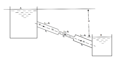
Fig. 5: Pipes in series
L1, L2, L3 = Length of pipes 1, 2 and 3 respectively
d1, d2, d3 = diameters of pipes 1, 2, 3 respectively
v1, v2, v3 = velocity of flow through pipes 1, 2, 3
f1, f2, f3 = coefficients of frictions for pipes 1, 2, 3
H = difference of water level in the two tanks
The discharge passing through each pipe is same


The difference in liquid surface levels is equal to the sum of the total head loss in the pipes.

If minor losses are neglected, then above equation becomes as

Key takeaways
The difference in tanks when pipe connected in series

Pipes in Parallel:
- Consider a main pipe which divides into two or more branches as shown in fig. And again join together downstream to form a single pipe, then the branch pipes are said to be connected in parallel.
- The discharge through the main is increased by connecting pipes in parallel.
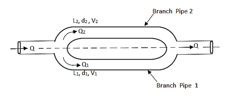
Fig. 6: Pipes are connected in parallel
- The rate of flow in the main pipe is equal to the sum of rate of flow through branch pipes.

In this arrangement, the loss of head for each branch pipe is same.
Hence, Loss of head for branch pipe 1 = Loss of head of branch pipe 2

Key takeaways
When pipes are connected in parallel loss of head for branch pipe1 = loss of head of branch pipe 2

Power is transmitted through pipe by allowing water to flow through a pipe.
Now consider a pipe AB connected to a tank as shown it.
Let,
H = Head of water at inlet
L = Length of the pipe
d = Diameter of the pipe
V = Velocity of flow in pipe
hf =Head loss due to friction
Head available at the outlet of the pipe,
=Head at inlet-Head loss due to friction
= H-hf =H-
Weight of water flowing through pipe/sec.
W = x Volume of water/sec.
= x Area× Velocity=
 ×
× d2×V
d2×V
Power transmitted at outlet of the pipe,
P = Weight of water per sec x Head at outlet
P= Watt
Watt
Efficiency of power transmitted,
ɳ=
=
=
ɳ=
Condition for Maximum Transmission of Power:
The condition for maximum transmission of power is obtained by differentiating Equation with respect to V and equating the same to zero.
∴ (P)=0
(P)=0
 =0
=0
 =0
=0
H= =3hf
=3hf
∴hf=H/3
The Equation is the condition for maximum transmission of power.
Maximum Efficiency of Transmission of Power:
Efficiency of power transmission through pipe is given by,
ɳ=
For maximum power transmission, hf=H/3
Maximum efficiency,
ɳ= =2/3
=2/3
∴ɳ%=66.67%
A syphon is a long-bent pipe is used for carrying water from a reservoir at a higher level to another reservoir at a lower level when the two reservoirs are separated by a hill or high-level ground.
The point C is highest point of syphon is called as summit.
The pressure at point C is less than atmospheric pressure as it lies above the free water surface in the tank A.
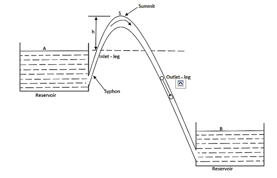
Fig.7: Siphon
The pressure at C can be reduced, theoretically, to -10.3 m of water but in actual practice is only 7.6 m of water (or 10.3-7.6=2.7 m of water absolute).
If the pressure becomes less than 2.7 m of water absolute, the dissolve air and other gases would come out from water and collected at the summit. It may be obstract the flow of water.
Syphon is used in following cases:
(a) To take out water from one reservoir to another reservoir separated by a hill or ridge.
(b) To drain out water from a channel without any outlet.
(c) To take out the water from a tank which does not have any outlet.
Working principle of syphon:
Negative or vacuum pressure is created in the syphon, so that liquid gets pushed into it.
The flow through syphon then remains continuous till pressure in syphon pipe remains negative but less than separation pressure.
At summit, we find the minimum pressure. Velocity or discharge through syphon can be obtained by applying Bernoulli's equation between A and Fig.as shown in.
Now applying Bernoulli's equation between section A and B,
 +
+ +ZA=
+ZA= +
+ +ZB+Losses
But and VA=VB=0
∴ZA-ZB=Losses
H= Loss of head at entry+ Head loss due to friction+ Head loss due to exit
H= 0.5 +
+ +
+ =
=
Where f= Friction factor=4f=4 coefficient of friction
L = Length of syphon AB
d =Diameter of the syphon
V =Velocity of flow
Now, applying Bernoulli's equation between A and C.
 +
+ +ZA=
+ZA= +
+ +ZB+Losses between AC
But  =0, VA=0, Vc=V,
Head loss between AC=Entry loss +Frictional loss
=0.5 +
+
∴ZA= +
+
But ZA-ZC=-hc
 =-
=-
This equation is used to find out,
 =Pressure head at summit
Hc = Height of summit above the surface in the higher level
L1= Length of inlet leg
- Consider a long pipeline AB connected to the other side of a tank that contains water height H from the center of the pipe. At the outer end of the pipe, a flow control valve is provided.
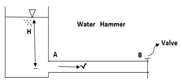
Fig. 8: Water hammer
- When the valve is fully open, water flows at a velocity, V in the pipe.
- If the valve is now shut off, the flow of water is interrupted by a high-pressure wave.
- This high-pressure wave will be passed along the pipe by a velocity equal to the velocity of the sound wave and can create a noise called Knocking,
- And this high-pressure wave has the effect of moving the walls of the pipe, hence the name water hammer.
- A pipe network is an interconnected system of pipes forming several loops of circuits.
- The pipe network is shown in figure.
- The examples of such networks of pipes are the municipal water distribution system in cities and laboratory supply system.
- In each system, it is required to determine the distribution of flow through the various pipes of the network.
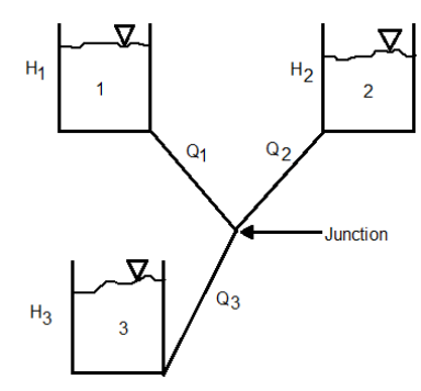
Fig. 9: Three reservoir problems
The following are the necessary conditions for any network pipes:
- The flow into each junction must be equal to the flow out of the junction. This is due to continuity equation.
- The algebraic sum of head losses round each loop must be zero. This means that in each loop, the loss of head due to flow in clockwise direction must be equal to the loss of head due to flow in anticlockwise direction.
- The head loss in each pipe is expressed as
- The value of R depends upon the length of pipe, diameter of pipe and coefficient of friction of Pipe. The value of n for turbulent flow is 2.
We know that


Therefore, 
- This head loss will be positive when the pipe is a part of loop and the flow in the pipe is clockwise.
- Generally, the pipe network problems are difficult to solve analytically. Hence, the methods of successive approximation are used. Example Hardy cross method.
- A group of interconnected pipes forming several loops or circuits is called as pipe network. e.g., municipal water distribution system in cities.
- Following are the various conditions to be satisfied by pipe network.
- According to the principle of continuity, the flow into each junction must be equal to the outflow of the junction.
- In each loop, the loss of head due to flow in clockwise direction must be equal to the loss of head due to flow in anticlockwise direction.
- The head loss in each pipe is expressed as h, = r Qn. The value of r depends upon the length of pipe, diameter of pipe and coefficient of friction of pipe. The value of n for turbulent flow is 2.
Hf = =
= (
( )^2 =
)^2 =
= = rQ2 where, r=
- The pipe network problems are difficult to solve analytically. Hence the methods of successive approximations are used. 'Hardy cross method' is one such method which is commonly used.
Numericals:
Q. Water is flowing through a tapered pipe having diameters 300 mm and 150 mm at section 1 and 2 respectively. The discharge through the pipe is 40 litre/sec. Section 1 is 10 m above datum and section 2 is 6 m above datum. Find the intensity of pressure at section 2 if that at section 1 is
Soln.:
Given
Q = 40 litre/sec=0.04 m²/sec
Z₁ = 10m
Z₂ =6m
d₁ =300mm=0.3 m
d2 = 150 mm-0.15m
P1 = 400 kN/m²
To find: P:
Area


By continuity equation,


By Bernoulli's equation


The intensity of pressure of section 2 is 436.84 kN/m²
Q. A pipe has a length of 200 m with a slope of 1 in 100. The diameter of pipes changes from 1.0 m at higher end to 0.5 m at lower end. Find the pressure at the lower end if the discharge flowing through pipe is 5.00 m/min and pressure at higher end is 45 kN/m².
Soln.:
Given:
L = 200 m,
P₁ =45 kN/m²
Slope = 1 in 100. z₁ = 0,
d₂ -0.5 m
Q = 5 m/min =5/60 = 0.0833 m/sec
To find: P₂
Slope of pipe is 1 in 100


(Since it is below z₁
i.e., datum, it is considered negative) = -2m
By continuity equation


By Bernoulli's equation


Multiplying by 9.81

Q. The top and bottom diameters of a 2m long vertical tapering pipe are 100 mm and 50 mm respectively. Water flows down the pipe at 30 liters por second. Find the pressure difference between the two ends of the pipe.
Soln.:
Given:
Q = 30 Lps = 0.03 m³/sec,
d1 = 0.05 m. d₂ = 0.1 m, z₁ = 0, z₂ = 2 m
Area


By continuity equation,


By Bernoulli's equation


:. The pressure difference between two ends of pipe is 10.415x 10³ Pa
Q. A venturimeter has an area ratio 9.1, the large diameter being 30 cm. During the flow, the recorded pressure head in the large section is 7.75 m and that at the throat is 5.5 m. Find the discharge through the meter if C,0.98.
Soln.:
Given:


Discharge of inlet
d1 = 0.3 m
Pressure at inlet 
Pressure head at throat 
Coefficient of discharge Cd, = 0.98
Area


Pressure head

Discharge


Q. A venturimeter is to be fitted to a pipe of area 0.01787 m² A maximum discharge of 5 m/min under a pressure of 4.5 m flows through the pipe. Find the diameter at the throat for no negative pressure at the throat.
Soln.:
Given:
a1 = 0.01767 m². Q = 5 m²/min=0.08333 m/sec
Pressure head = 4.5 m
To find: Diameter of throat i.e., d
Considering the venturimeter to be horizontal
Applying Bernoulli’s equation at section (1) and (2)


But Z1=Z2
And as there is no negative pressure at throat considering


Discharge Q

(Assuming C=0.98)


Q. A venturimeter is fitted to 25 cm diameter pipe. A discharge 10 m³/s flowing through venturimeter, develops a venturi head of 3.5 m of water. Find the minimum diameter of throat so that there is no negative head developed.
Soln.:
Given:
D = 25 cm = 0.25 m, Q = 10 m³/s,
To find:
d for no negative head developed.
a₁ = area of inlet = 

Cd=1


Squaring both side


Q. A pitot tube records of 7.85 kN/m² as the stagnation pressure when it is head at the centre of pipe of 250 mm diameter conveying water. The static pressure in the pipe is 40 mm of mercury (gauge-vacuum). Calculate the discharge through the pipe assuming that the mean velocity of flow is 0.8 times the maximum velocity. Take C, = 0.98.
Soln.:
Given:
Stagnation pressure p₁= 7.85 kN/m²
Pressure at center of pipe = 40 mm of mercury
P2 = -0.04×13.6 x 9.81-5.336 kN/m
Mean velocity = 0.8 x maximum velocity
Pressure head

Maximum velocity

Mean velocity (V)=0.8 x Maximum velocity = 0.8 x 5.033=4.0264 m/sec
Discharge Q

Discharge through the pipe 197.65 Lps.
Q. A pitot static tube is used to measure velocity of an aeroplane. U-tube differential manometer gives deflection of 100 mm of water. If specific weight of air is 12 N/m and coefficient of pitot tube is 0.98. Determine speed of aeroplane. Neglect compressibility effects.
Soln.:
Given:
C = 0.98. Ya = 12 N/m².
x = 100 mm of water = 0.1m
To find: Speed of aero plane V =?
Specific gravity of air

Specific gravity of water
Sw = 1

Speed of aircraft

The speed of aeroplane is 39.28 m/s.
Q. An Orifice of diameter 12 cm is inserted in a pipe of 24 cm diameter. The end pressure gauge fitted upstream and 2 downstream of the orifice metre gives readings 29.43 N/cm and 14.72 N/cm respectively. Co-efficient of discharge of orifice metre is given by 0.6. Find the discharge of water through pipe.
Soln.:
Given:
d, = 24 cm = 0.24 m, p, 29.43 N/cm² = 294.3 kN/m² 4-12 cm-0.12 m. p₂= 14.72 N/cm² Cv= 0.6
Area A₁


Pressure difference

Discharge, Q


The discharge through the pipe is 120 Lps.
Q. Two reservoir at different elevations are connected with a compound pipe of 1 km total length; consisting of two sections. First section connect to higher level reservoir is 500 m long and 200 mm in a diameter and other half is connected to lower-level reservoir and has 100 mm diameter. Darcy Weisbach friction factors for the pipes are 0.019 and 0.02 respectively. If velocity of flow of water in the second section is 1.5 m/s. Find the difference in water levels in the reservoirs considering all losses. Find the rate of flow of water also. Find diameter of single uniform diameter pipe replace the above pipeline to carry same discharge. Take f = 0.018 for the pipe.
Soln.:
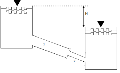
Given:
d₁= 200 mm = 0.2 m
f₁ = 0.019 d₂ = 100 mm = 0.1 m
f₂ = 0.02
L = 1 km
By continuity equation,
A₁V₁ = A₂V₂


Case I:
Major losses = Loss due to friction Loss due to friction in pipe 1 in pipe 2


Minor losses = Loss at entry + Loss due to contraction + loss at exit


Total losses = Major losses+ Minor losses

Case II: New pipe with uniform diameter.


The diameter of single equivalent pipe is 114.16 mm.
Q. Three pipes 300 m, 150 m, 200 m long having diameters 300 mm, 200 mm and 250 mm respectively are connected in a series in the same order. Pipe having 300 mm diameter in connected to the reservoir. Water level in the reservoir is 15 m above the pipe are 0.018, 0.02 and 0.019. Determine the flow rate, magnitude of loss in each pipe section, and the diameter when the three pipes are replaced by a single pipe (f = 0.016) to give the same discharge. Neglect the minor losses.
Soln.
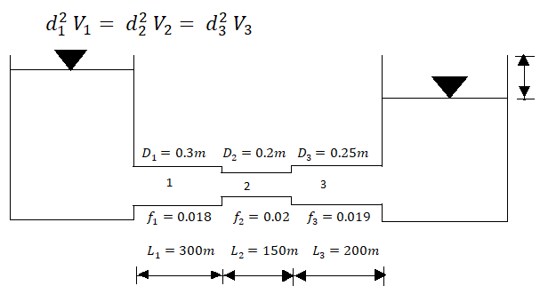
Let V, V, and V, are the velocities in the pipe 1, 2, 3 respectively.
By continuity equation


Major loss = hf1+hf2+hf3


Flow rate

Head loss in each pipe


Diameter when three pipes are replaced by single pipe
Using Dupit’s equation


References:
1.Hibbler, “Fluid Mechanics in SI units”1/e Pearson Education, Noida
2.Cengel & Cimbala, “Fluid mechanics” TMH, New Delhi
3.Katz, “Introductory Fluid Mechanics” Cambridge University Press
4.Pnueli & Gutfinger, “Fluid Mechanics” Cambridge University Press
5.Modi & Seth “Hydraulics & Fluid Mechanics” Standard Publication