Unit - 4
Equation of motion for laminar flow through pipes
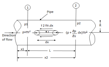
Fig. 1: Circular pipes
Fig. Shows a horizontal circular pipe of radius R, having laminar flow of fluid through it.
Consider a small concentric cylinder of radius r and length dx as a free body.
If  is the shear stress, the shear force F is given by
F =  x 2
x 2  r x dx
Let P be the intensity of pressure at left end and the intensity of pressure at the right end be (
Thus, the force acting on the fluid element are:
i) The shear force,  x 2
x 2 r x dx on the surface of fluid element.
Ii) The pressure force, P x  on the left end.
Iii) The pressure force, ( on the right end.
For steady flow, the net force on the cylinder must be zero.
 [ p x
[ p x  - (
- ( ] –
] – 
 -
-  -
-

Shear stress is zero at the centre of pipe (r = 0) and maximum at the pipe wall given by
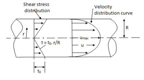
Fig. 2: When shear stress is zero
 (
( )
)
From Newton’s Law of viscosity

In this equation, the distance y is measured from the boundary. The radial distance r is related to distance y by the relation.
y = R-r ordinate y = -d r

Comparing two values of 
 =
= 
 du =
du =  (
( )r.dr
)r.dr
Integrating the above equation w. r. t. ‘r’ we get
 u =
u =  .
.  r2 + C --------------- (ii)
Where C is the constant of integration and its value is obtained from the boundary conditions.
At r = R, u = 0
 0 =
0 =  .
.  R2 + C or C =
 .
.  R2
R2
Substituting this value of C in eqn. (ii) we get,
 u =
u =  .
.  r2
r2 .
.  R2
R2
 u = -
u = -  .
.  (R2 – r2)
Shows that velocity distribution curve is a parabola.
The maximum velocity occurs, at the centre and is given by.
 umax = -
  R2
R2
When a small sphere is moving through a viscous fluid with a constant velocity U, a drag force is experienced by the sphere opposite to its motion. This drag force on the sphere is given by-

Where D = diameter of sphere for low value of Re
v=velocity of sphere,
 = fluid density
This is known as stoke's law and is valid for speeds of flow which gives Reynold's number less than one.
Following are the assumptions made by stoke's law:
- The inertia force acting on the body is very small as compared to viscous forces and can be neglected.
- Wall of vessel containing the fluid are not so near as to affect the flow around the sphere.
- There is no slip between the fluid and the sphere.
- The sphere is rigid. Falling sphere method of measuring viscosity of a fluid is based on stoke's law.
According to Prandtl, the mixing length (l) is defined as the average lateral distance through which a small mass of fluid particles would move from one layer to the other adjacent layers before acquiring the velocity of the new layer.
He assumed that components u' and v' are of the same order and the velocity fluctuation in x direction is related to the mixing length as


When the viscous action is also included, the total shear stress may be expressed as

Above is used for most of the turbulent flow problems for determining the shear stress.
The velocity distribution for turbulent flow in pipes is given by Equation
u =2.5
For turbulent flow for y = 0, v=- at wall and hence at some finite distance from wall say y = y', the velocity u=0
∴0=2.5
C=-2.5
Substituting the value of C is Equation
u =2.5 - 2.5
- 2.5
u=2.5
∵ =2.3
=2.3

From Nikuradse's experimental studies of turbulent flow of smooth pipe,
y’ =
y’ =
Substituting the value of y' in Equation
∴
=5.75
 +5.55)
This equation is known as Karman-Prandtl equation for velocity distribution near hydrodynamically smooth boundaries.
Velocity Distribution for Turbulent Flow in Rough Pipes:
Karman-Prandtl equation:
For rough pipe, the laminar sub-layer is completely destroyed. It is found that y' is directly proportional to k
∴y’=
Substituting the value of y in Equation


= +
+
 =
=
This equation is known as Karman-Prandtl equation for velocity distribution near hydrodynamically rough boundaries.
It is the distance from the boundary to the point where velocity of fluid is approximately equal to 99% of free stream velocity (U).
It is denoted by ' '
'
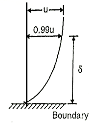
Fig: 3
Velocity variation in turbulent boundary layer is logarithm and is generally represented by power law,

Where n varies from 5 to 10 depending upon Reynold’s number.
For turbulent boundary layer and R., ranging from 5 x 10⁷ and 2 x 10⁷

This is known as one-seventh power law. This is nth applicable to the thin laminar sublayer which is very near to thin boundary.
Blasius's relation of shear stress for flat plate is taken as,

For Rex, ranging from 5x 10³ to 107, we have
a) Boundary layer thickness,
b) Local coefficient of drag 
c) Average coefficient of drag 
This equation is applicable for boundary layer turbulent throughout the plate,

It is applicable for the boundary layer which is partly lamina and partly turbulent.
It is the distance perpendicular to the boundary, by which the boundary should be displaced outward to compensate for reduction in the discharge in the boundary layer formation.

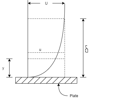
Fig: 4
Derivation:
Consider the fluid flow having free-stream velocity 'U' over a thin smooth plate as shown in Fig.
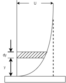
Fig: 5
Consider elementary strip at a distance 'y' from the plate and 'dy' is thickness.
Let u be the velocity at elemental strip and b is width of plate.
Mass per second through strip, =
Mass per second through strip if no plate is placed i.e.
u =U
= …..(2)
∴Total reduction of mass/second of strip,
= ….(3)
….(3)
∴Total reduction of mass/ second for whole boundary layer=
Let the plate displaced by a distance  * and velocity of flow for the distance & is free stream velocity 'U'.
∴Loss of mass/second flowing through distance  *
*
= …..(4)
Equating Equation 3 and 4,
 =
=
∴ =
= )dy
)dy
Key Takeaways:
It is the distance perpendicular to the boundary, by which the boundary should be displaced outward to compensate for reduction in the discharge in the boundary layer formation.
It is the distance measured perpendicular to the solid boundary, by which boundary will be displaced to compensate for the reduction in momentura of the flowing fluid due to boundary layer formation. It is denoted by ' '.
'.
Derivation:
Momentum of fluid/sec=Mass /Sec x Velocity
= ( .ubdy) u=
 u²b dy ….(1)
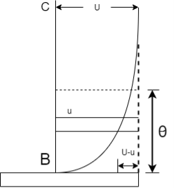
Fig: 6
Momentum of fluid if no plate is placed
(u=V) = ( ubdy) U …..(2)
∴Loss of momentum/sec through strip
=
=
Total loss of momentum/sec through BC,
= ….(3)
….(3)
Let  be the distance by which plate is displaced, when fluid flowing with constant velocity.
Loss of momentum/sec at a distance  with velocity U
= Mass of flow through  x Velocity
= ( x
x x b x U) U=p
 bU² ….(4)
Equating Equations (iii) and (iv),


Key Takeaways:
It is the distance measured perpendicular to the solid boundary, by which boundary will be displaced to compensate for the reduction in momentura of the flowing fluid due to boundary layer formation. It is denoted by 'θ'.
It is the distance perpendicular to solid boundary, by which the boundary should be displaced to compensate for the reduction in kinetic energy of the flowing fluid in the formation of boundary layers.
Kinetic energy of fluid, if plate is placed
= mV² = (
 ubdy)u² …..(1)
Kinetic energy of fluid if no plate is placed =  m V² = (
 ubdy) U² …..(2)
∴Loss of Kinetic energy= ub(
ub( dy
dy
∴Total loss of Kinetic energy in BC=
 ub
ub dy ...(3)
Loss of Kinetic energy through  of fluid flowing with velocity U,
=1/2×Mass x Velocity²
= ….(4)
….(4)
Equating Equations (iii) and (iv),


Key takeaways:
It is the distance perpendicular to solid boundary, by which the boundary should be displaced to compensate for the reduction in kinetic energy of the flowing fluid in the formation of boundary layers.
Following are the realistic utility of momentum equation:
- Flow even though bend pipes
- Jet propulsion and propellers
- Fluid waft even though desk bound and shifting plates or vanes.
- Non-uniform waft via saddens enlarged pipes.
- Hydraulic leap in open channels
A flat smooth plate is placed parallel to the direction of flow, the flow in the boundary layer is laminar though the main flow is turbulent near to the trading edge of plate. This layer of fluid is said to be Laminar boundary layer.
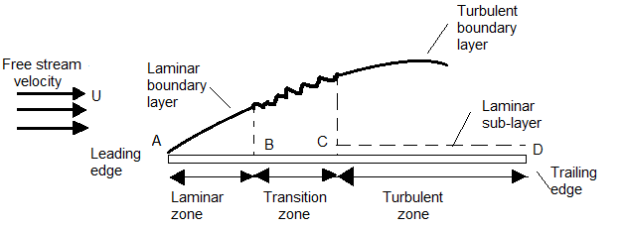
Fig: 7
(Re)x=
Where, x = Distance from leading edge,
U = Free stream velocity
v=Kinematic viscosity
If the length of the plate is more than laminar zone (x), the thickness of boundary layer increase in downstream direction due to the increase in 'R'. The layer became unstable and boundary ex layer changes from laminar to turbulent over a short length i.e., i transits zone. The layer continues to increase in downstream, such layer is called as Turbulent boundary layer.
(Re)x,> 5×10⁵, the layer is turbulent boundary layer
Key Takeaways:
If the length of the plate is more than laminar zone (x), the thickness of boundary layer increase in downstream direction due to the increase in 'R'. The layer became unstable and boundary ex layer changes from laminar to turbulent over a short length i.e., i transits zone. The layer continues to increase in downstream, such layer is called as Turbulent boundary layer.
Laminar sub layer is the region in the turbulent boundary layer zone, adjacent to the solid surface of the plate.
The velocity variation in this region is assumed linear as it’s a very thin layer and so that velocity gradient (dy/dx) can be considered constant.
Shear stress in laminar sub-layer
 =
=
For linear variation
 =
=
Key Takeaways:
Laminar sub layer is the region in the turbulent boundary layer zone, adjacent to the solid surface of the plate.
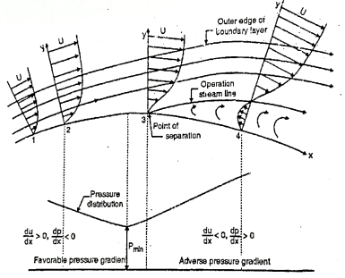
Fig: 8
Effect of pressure gradient on boundary layer surface:
Consider steady flow and apply boundary condition at the solid boundary where y = 0, u = 0.
∴
Depending upon the curvature the boundary, there are three possible cases.
1)There is gradual increase in velocity and drop in pressure as the flow passes from 1 to 2 i.e., pressure drop in the direction dp of flow,  <0. The entire boundary layer moves forward, till the pressure gradient less than zero. This condition is called as favourable pressure gradient.
2)The flow retards and pressure increase as flow passes downstream from section 2. This condition is called as adverse pressure gradient. Both pressure and shear force produced continuous retardation in the flow momentum and a stage Coolness when the momentum of the fluid is unable to overcome the surface resistance. It is developed near the curved du surface where velocity gradient  = 0 i.e., at section 3. This dy point at which the boundary layer is on the verge of separation from the surface is called as point of separation.
3)The fluid separated from the surface due to continuous retardation of flow. It has tendency to flow in a direction opposite to the main flow. It occurs beyond the point 3. Where  >0
>0
Location of separation point:
For the given velocity profile, there are three conditions for location of separating point:
1)If  is positive, the flow will remain attached with the surface.
2) If  is zero, the flow is on the verge of separation.
3) If  is negative, the flow is separated.
Methods of controlling the Separating of Boundary Layer:
1) Streamlining body
The streamline of a body is designed in such a way that the point of separation shifted as far as possible on downstream. Due to which wake region becomes narrower and the pressure drug gets reduced.
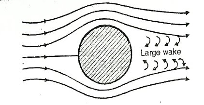
Fig. 9: Sphere
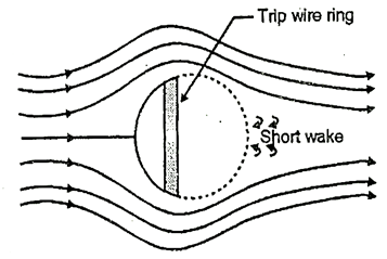
Fig. 10: Tripwire ring

Fig. 11: Aerofoil
2) The artificial roughness (e.g., golf ball) is provided in the approach section, which changes the laminar boundary layer into the turbulent boundary layer.
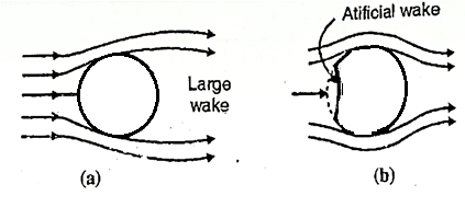
Fig: 12
3) Providing the slot near the leading edge so that the fluid layers remain attached to the upper surface of the body for its entire length.
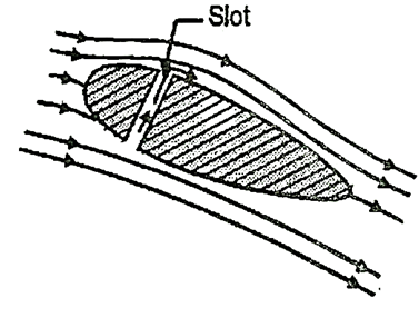
Fig: 13
4) Section in which the retarded fluid is sucked out through suction slots in the boundary layer surface.
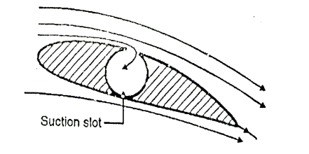
Fig: 14
5) Blowing in which addition energy is supplied in the retarded fluid in the boundary layer by injecting high velocity fluid from the blower.
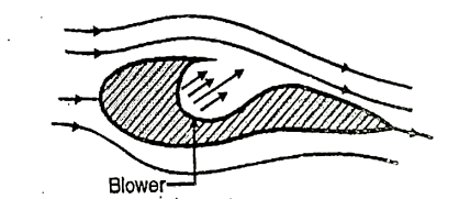
Fig: 15
6) Guide vane and splitter vanes are provided in a confined passage to avoid separation in a flow.
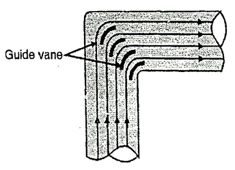
Fig: 16
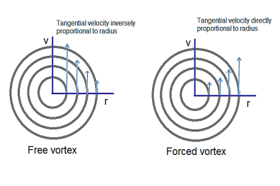
Fig. 17: Vortex flow
Vortex flow: the circulating weight of a liquid or a liquid flow in a curved path.
Free vortex flow
No external torque or power required. Liquid circulation under certain energies previously given to them. In free vortex machines, the overall energy flow remains constant. There is no power connection between the external source and the flow and any power dissipation of the equipment in motion.
Liquid circulation is due to the preservation of angular pressure.
Velocity equals radius.
For a Free vortex flow
v r = constant or v = c/ r
Free vortex flow - Velocity equation
At the center (r = 0) of the velocity rotation approaches infinitely, that point is called a single point.
Free flow of vortex is irrational; therefore, it is also known as irrotational vortex.
In free vortex flow, Bernoulli's equation can be used.
Examples include a whirlpool in a river, water flowing from a bathtub or sink, flowing into the space of a centrifugal pump and flowing around a circular bend of a pipe.
Forced vortex flow
To maintain the forced flow of the vortex, it required a continuous supply of power or external torque.
All liquid particles circulate with an infinite angular velocity ω as a solid body. Therefore, the flow of a forced vortex is called a solid body rotation.
Tangential velocity is directly proportional to the radius.
v = r ω
ω = Angular speed.
r = Radius of particle fluid from the axis of rotation.
The profile of the vortex flow area is illustrated.
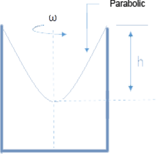
Fig. 18: Forced vortex Verified vortex - Height rate
At the forced vortex force each unit weight increases with increasing radius.
The forced vortex is not unthinkable; instead, the rotational flow with a constant vorticity 2ω.
Examples of forced vortex flow rotate a vessel containing a liquid with constant angular velocity, flowing within a centrifugal pump.
Key takeaways
There are two types of vertex
- Free vortex0
- Fixed vortex
References:
1.Hibbler, “Fluid Mechanics in SI units”1/e Pearson Education, Noida
2.Cengel & Cimbala, “Fluid mechanics” TMH, New Delhi
3.Katz, “Introductory Fluid Mechanics” Cambridge University Press
4.Pnueli & Gutfinger, “Fluid Mechanics” Cambridge University Press
5.Modi & Seth “Hydraulics & Fluid Mechanics” Standard Publication