Unit - 5
Drag and lift
Drag:
- Drag is a mechanical pressure. It is generated with the aid of using the interplay and speak to of a stable frame with a fluid (liquid or gas).
- It isn't generated with the aid of using a pressure subject, withinside the experience of a gravitational subject or an electromagnetic subject, wherein one item can have an effect on every other item without being in bodily contact.
- For drag to be generated, the stable frame should keep up a correspondence with the fluid.
- If there's no fluid, there's no drag. Drag is generated with the aid of using the distinction in pace among the stable item and the fluid.
- There should be movement among the item and the fluid. If there's no movement, there's no drag.
- It makes no distinction whether or not the item movements via a static fluid or whether or not the fluid movements beyond a static stable item.
- Drag is a pressure and is consequently a vector amount having each a value and a course.
- Drag acts in a course this is contrary to the movement of the plane. Lift acts perpendicular to the movement.
- There are many elements that have an effect on the value of the drag. Many of the elements additionally have an effect on raise however there are a few elements which might be precise to plane drag.
Lift:
- Lift is a mechanical pressure. It is generated via way of means of the interplay and make contact with of a stable frame with a fluid (liquid or gas).
- It isn't always generated via way of means of a pressure field, withinside the experience of a gravitational field, or an electromagnetic field, in which one item can have an effect on any other item without being in bodily contact.
- For raise to be generated, the stable frame needs to keep in touch with the fluid: no fluid, no raise.
- The Space Shuttle does now no longer live-in area due to raise from its wings however due to orbital mechanics associated with its speed. Space is almost a vacuum.
- Without air, there's no raise generated via way of means of the wings.
Key Takeaways:
Drag is a mechanical pressure. It is generated with the aid of using the interplay and speak to of a stable frame with a fluid (liquid or gas). Lift is a mechanical pressure. It is generated via way of means of the interplay and make contact with of a stable frame with a fluid (liquid or gas).
- The aerodynamic drag on an item relies upon on numerous elements, along with the shape, length, inclination, and glide situations. All of those elements are associated with the price of the drag via the drag equation.
D = Cd * .5 * rho * V^2 * A
- Where D is same to the drag, rho is the air density, V is the velocity, A is a reference area, and Cd is the drag coefficient.
- The drag coefficient is a dimensionless quantity that characterizes all the complicated elements that have an effect on drag.
- The drag coefficient is commonly decided experimentally the use of a version in a wind tunnel.
- In the tunnel, the velocity, density, and length of the version are known. Measuring the drag then determines the price of the drag coefficient as given through the above equation.
- The drag coefficient and the drag equation can then be used to decide the drag on a comparable formed item at exclusive glide situations so long as numerous glide similarity parameters are matched.
- In particular, Mach quantity similarity ensures that the compressibility consequences are effectively modeled, and Reynold’s quantity similarity ensures that the viscous consequences are effectively modeled.
- The Reynolds quantity is the ratio of the inertia forces to the viscous forces and is given through:
Re = V * rho * l / mu
In which l is a reference length, and mu is the viscosity coefficient.
- For maximum aerodynamic objects, the drag coefficient has an almost consistent price throughout a big variety of Reynolds numbers.
Key Takeaways:
The aerodynamic drag on an item relies upon on numerous elements, along with the shape, length, inclination, and glide situations. All of those elements are associated with the price of the drag via the drag equation.
D = Cd * .5 * rho * V^2 * A
- An airfoil (American English) or aerofoil (British English) is the cross-sectional form of an item whose movement thru a fueloline is able to producing widespread carry, which includes a wing, a sail, or the blades of propeller, rotor, or turbine.
- A stable frame transferring thru a fluid produces an aerodynamic pressure. The element of this pressure perpendicular to the relative freestream pace is known as carry.
- The element parallel to the relative freestream pace is known as drag. An airfoil is a streamlined form this is able to producing substantially greater carry than drag.
- Airfoils designed to be used at unique speeds fluctuate of their geometry: the ones for subsonic flight typically have a rounded main edge, at the same time as the ones designed for supersonic flight have a tendency to be slimmer with a pointy main edge.
- All have a pointy trailing edge. Foils of comparable feature designed with water because the operating fluid are known as hydrofoils.
Key Takeaways:
An airfoil (American English) or aerofoil (British English) is the cross-sectional form of an item whose movement thru a fueloline is able to producing widespread carry, which includes a wing, a sail, or the blades of propeller, rotor, or turbine.
- Magnus effect, technology of a sidewise pressure on a spinning cylindrical or round stable immersed in a fluid (liquid or gas) whilst there may be relative movement among the spinning frame and the fluid.
- Named after the German physicist and chemist H.G. Magnus, who first (1853) experimentally investigated the impact, it's far answerable for the “curve” of a served tennis ball or a pushed golfing ball and influences the trajectory of a spinning artillery shell.
- A spinning item transferring via a fluid departs from its instantly course due to stress variations that increase withinside the fluid because of pace adjustments caused via way of means of the spinning frame.
- The Magnus impact is a selected manifestation of Bernoulli’s theorem: fluid stress decreases at factors wherein the rate of the fluid increases. In the case of a ball spinning via the air, the turning ball drags a number of the air round with it.
- Viewed from the location of the ball, the air is speeding via way of means of on all sides. The drag of the aspect of the ball becoming the air (into the course the ball is traveling) retards the airflow, while on the opposite aspect the drag accelerates the airflow.
- Greater stress at the aspect wherein the airflow is bogged down forces the ball withinside the course of the low-stress place on the alternative aspect, wherein a relative growth in airflow occurs.
Key Takeaways:
Magnus effect, technology of a sidewise pressure on a spinning cylindrical or round stable immersed in a fluid (liquid or gas) whilst there may be relative movement among the spinning frame and the fluid.
- The ratio of the corresponding forces acting at the corresponding points in the model and prototype should be equal, for the dynamic similarity between the model and the prototype.
- This means that the dimensionless numbers should be same for the model as well as the prototype.
- Actually, it is very difficult to satisfy the condition that all dimensionless number are same for both model and prototype.
- The models are designed on the basis of the force which is dominating in the flow situation.
- The laws on which models are designed for dynamic similarity are called as model laws or similarity law.
- Following are the model’s laws:
- Reynolds model law
- Froude model law.
- Euler model law
- Mach model law
- Weber model law.
Key Takeaways:
The laws on which models are designed for dynamic similarity are called as model laws or similarity law.
- If the ratio of corresponding length dimensions in the model and prototype are equal, then geometric similarity exists.
- It refers to similarity of shape or form of model and prototype.
For geometric similarities, scale ratio (Lr)
 =Lr
=Lr
Where, Lm, bm, hm are length, width and height of model Lp, bp, h, are length, width and height of prototype.
Area scale ratio, Ar= =
= ^2
^2
Volume scale ratio, Vr= =
= ^3
^3
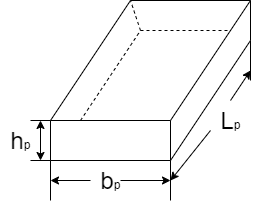
Fig. 1: Prototype
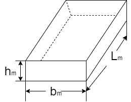
Fig. 2: Model
Key Takeaways:
If the ratio of corresponding length dimensions in the model and prototype are equal, then geometric similarity exists.
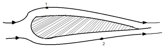
Fig. 3: Prototype
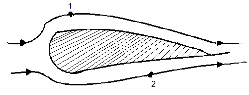
Fig. 4: Model
- If the ratios of the velocity and acceleration at the corresponding points in the model and at the corresponding points in the prototype are the same, kinematic similarities are existing.
- It refers the similarity of motion between model and prototype.
- Kinematic similarity stipulates that (i) paths of the homologous moving particles are geometrical similar. (ii) ratios of the kinematic parameters of the homologous particles are equal.
- Homologous particles refer to the corresponding fluid particles of the two systems.
- The velocity and acceleration are vector quantities, so that, not only the ratio of magnitude but also the direction should be parallel.
- For kinematic similarities, scale ratio velocity scale ratio
 =
=
Acceleration scale ratio  =
=
Key Takeaways:
If the ratios of the velocity and acceleration at the corresponding points in the model and at the corresponding points in the prototype are the same, kinematic similarities are existing.
- If the ratio of all the forces acting at the homologous points in model and prototype are equal.
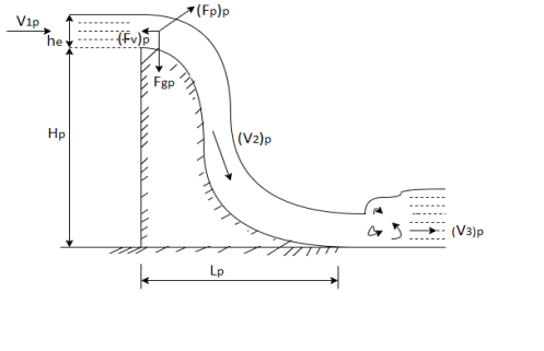
Fig. 5: prototype
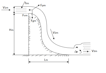
Fig. 6: Model
- It refers to the similarity of masses and forces of the corresponding particles of flow.
- Both geometric and kinematic similarities are pre-requisite for dynamic similarity.
- Force is the vector quantities, so that not only ratio of magnitude but also the direction should be parallel.
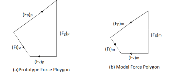
Fig. 7: Prototype and Model force polygon resp.
- For dynamic similarity,
Force scale ratio 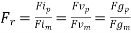
Where, (Fi)p, (Fv)p, (Fg)p = Inertia force, viscous force and gravity force at a point in prototype (
Fi) m, (Fv)m, (Fg)m= Inertia force, viscous force and gravity force at corresponding point in model.
Key Takeaways:
If the ratio of all the forces acting at the homologous points in model and prototype are equal.
Distorted models:
- Distorted models are those which are not perfectly geometrically similar to the prototype.
- Different scale ratio is used in different direction.
- Particularly, in case of shallow rivers, where depth is small compared to the width, without distortion the depth of flow in the model will be so small that measurements may not be accurate and the surface tension effect will be prominent which will not be present in prototype. Hence it is necessary to distort the models in the vertical direction.
- In the design of model, hydraulic similitude is of prime importance and not that the geometric similads. Therefore, by distortion of the model scale, even though the model is not look, like the prototype, but it gives the satisfactory results.
Advantages and Disadvantages of Distorted Models:
Advantages:
- Due to substantial height obtained by distortion, measurement in the vertical direction is fairly accurate.
- Hydraulic similitude is achieved due to distortion.
- Turbulent flow in the model becomes possible.
- Cost of model can be reduced.
- Viscous effects absent in the prototype, are eliminated in the model. For example, increase in the bed slope of the model. In an otherwise geometrically similar model, increases the velocity in the model, which decreases the effect of viscosity.
- Movement of sand and silt in the model can be simulated to that of the prototype.
- Adoption of the distorted model, reduces the size of the model, which saves the space and facilitates the easy operation of the model.
Disadvantages:
- Due to different scales in the different directions, the velocity and pressure distribution in the model is not the same as that in the prototype.
- Slopes, curves, bends and cutting in earth is not truly represented in the model.
- Waves are not simulated in the distorted models.
Even though there are many advantages of the distorted models, interpretation of the model results for the application to the prototypes is not direct but it needs some amount of manipulation. However, due to distortion of models, the accuracy of results can be assured.
Undistorted Models:
- Undistorted models are those which are perfectly similar in all respects with its prototype.
- Scale ratio for the linear dimensions of the model and its prototype is always same in undistorted models.
- Analysis of undistorted models is simple and the behaviour of prototype can be easily predicted from result of this analysis.
Key Takeaways:
Distorted models are those which are not perfectly geometrically similar to the prototype. Undistorted models are those which are perfectly similar in all respects with its prototype.
- Dimensional analysis is a mathematical technique which deals with the dimensions of the physical quantities involved in the phenomenon.
- Some problems of fluid mechanics are very complex in nature and also very difficult to solve. The solution of such problems is considerably simplified the use of dimensional analysis.
- It is based on the assumption that the phenomenon can be expressed by a dimensionally homogenous equation with certain variables.
- Now-a-days, dimensional analysis is widely used in research work for developing design criteria and also for conducting model test.
Advantages of Dimensional Analysis
- By dimensional analysis, the functional relationship between dependent and non-dependent variables can be expressed into dimensionless terms.
- In model testing, it reduces the number of variables into three number.
- By dimensional analysis, design curves can be developed from experimental data or direct solution of the problem.
- It used to change the theoretical equation into a simple dimensionless form.
- By dimensional analysis, any complex fluid flow phenomenon can be easily solved.
- It helps to convert the units of quantities from one system to another system.
Key Takeaways:
Dimensional analysis is a mathematical technique which deals with the dimensions of the physical quantities involved in the phenomenon.
- When a large number of physical variables are involved Rayleigh’s method of dimensional analysis becomes increasingly laborious and cumbersome.
- Buckingham’s method is an improvement over the Rayleigh’s method.
- Buckingham’s designated the dimensionless group by the letter Π. It is therefore often called Buckingham Π-Method.
- The Buckingham’s Π-Method states as follows:
“If there are n variables in a dimensionally homogeneous equation and if these variables contain fundamental dimensions (such as M, L, T, etc.) then the variables are arranged into (n-m) dimensionless terms.
- These dimensionless terms are called Π– terms.”
Mathematically, if any variable X1, depends on independent variables, X2, X3, X4,…… Xn; the functional equation may be written as
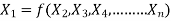 -------- 1
Equation 1 can also be written as
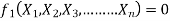 -------- 2
It is dimensionally homogeneous equation and contains n variables.
If there are m fundamental dimensions, then according to Buckingham’s Π – theorem, it can be written in terms of number of Π – terms in which number of Π terms is equal to (n-m).
Hence equation 2 becomes as
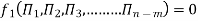 --------3
Each dimensionless  – term is formed by combining m variables out of the total n variables with one of the remaining (n-m) variable.
These m variables which appear repeated in each of  – terms are consequently called repeating variables and are chosen from among the variables such that they together involve all the fundamental dimensions and they themselves do not form a dimensionless parameter.
Let in the above case X2, X3 and X4 are the repeating variables if the fundamental dimensions m (M, L, T) = 3, then each term is written as:
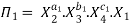
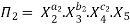
.
.
.
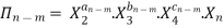 -------- 4
Where a1, b1, c1, a2, b2, c2 etc. are the constants, which are determined by considering dimensional homogeneity. These values are substituted in equation 4 and values of  are obtained. These values of Π’s are substituted in equation 3.
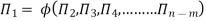
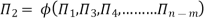
The final general equation for the phenomenon may then be obtained by expressing anyone of the Π – terms as a function of the other as:


Key takeaways:
The final general equation for the phenomenon may then be obtained by expressing anyone of the Π – terms as a function of the other as:
The ratio of two forces is called as dimensionless parameter or number. The following are the important dimensionless numbers used in fluid mechanics.
- Reynold's number
- Froude's number
- Weber's number
- Euler's number
- Mach's number.
Reynold’s Number:
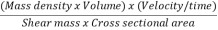
The ratio of inertia force to the viscous force is called as Reynold's number. It is denoted by Re.
=
=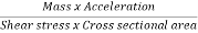
=
=
= =
=
= =
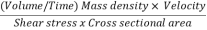
= =
= =
= ∵v=
∵v=
Applications of Reynolds number:
Motion of completely submerged bodies like submarine, aeroplanes and automatic with low velocity, Incompressible flow through pipes, flow through low-speed turbo machine in which viscous forces are predominant.
Froude's Number:
The square root of the ratio of inertia force and gravitational force is called Froude's number. It is denoted by F
∴Fr=
=
=
= ∵V=
∵V= =T=
=T=
= =
= =
=
Application:
Open hydraulic structure such as spillways, wiers, open channel flow, sluices etc. in which force due to gravity are predominant.
Weber's Number
The square root of the ratio of the inertia force to the surface tension force. It is denoted by We.
We= =
=
= ∵A/T=Q=V.A
= ∵A=L2=
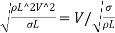
Application:
Capillary movement of water in soils, flow of blood in veins and arteries where the surface tension effects are predominant.
Euler's Number:
The square root of the ratio of inertia force to the pressure force is called as Euler's ratio.
= =
=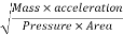
= =
= =
=
= ∵A/T=Q=V.A
Application:
In cavitation study where pressure force is predominant.
Mach's Number or Cauchy's Number:
The square root of the ratio of inertia force to the elastic force is called as Mach's number or Cauchy's number.
MN = =
=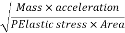
= =
= =
=
= ∵A/T=Q=V.A
Application:
In compressible fluid flow, problems at high speed such as high velocity flow in pipes, water hammer, motion of high-speed objects like aeroplane, projectile and missiles. Where the elastic force (compressibility effect) is predominant.
Key Takeaways:
The ratio of two forces is called as dimensionless parameter or number. The following are the important dimensionless numbers used in fluid mechanics.
- Reynold's number
- Froude's number
- Weber's number
- Euler's number
- Mach's number.
- Computational Fluid Dynamics (CFD) is the simulation of fluids engineering structures the usage of modeling (mathematical bodily hassle formulation) and numerical methods (discretization methods, solvers, numerical parameters, and grid generations, etc.).
- Firstly, we've a fluid hassle. To remedy this hassle, we have to recognize the bodily homes of fluid with the aid of using the usage of Fluid Mechanics. Then we are able to use mathematical equations to explain those bodily homes.
- This is Navier-Stokes Equation and it's far the governing equation of CFD. As the Navier-Stokes Equation is analytical, human can recognize it and remedy them on a bit of paper.
- But if we need to remedy this equation with the aid of using computer, we should translate it to the discretized form. The translators are numerical discretization methods, which includes Finite Difference, Finite Element, Finite Volume methods. Consequently, we additionally want to divide our entire hassle area into many small components due to the fact our discretization is primarily based totally on them.
- Then, we are able to write packages to remedy them. The usual languages are Fortran and C. Normally the packages are run on workstations or supercomputers. At the end, we are able to get our simulation effects.
- We can examine and examine the simulation effects with experiments and the actual hassle. If the effects aren't enough to remedy the hassle, we should repeat the system till discover glad solution. This is the system of CFD.
Key Takeaways:
Computational Fluid Dynamics (CFD) is the simulation of fluids engineering structures the usage of modeling (mathematical bodily hassle formulation) and numerical methods (discretization methods, solvers, numerical parameters, and grid generations, etc.).
Numericals:
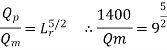
Q. The performance of a spillway is to be studied by means of a model constructed to a scale of 1:9. Determine: (1) Rate of flow in the model for a prototype discharge of 1400 m/s.(ii) Energy lost in the prototype if the energy loss in model is 0.3 kW.
Given: Scale of Model 1:9 ∴Lr=9
Discharge of prototype Qp=1400m3/s
Since it is spillway, Froude number must be applicable.
Using Discharge scale ratio
∴
Energy loss

Given Em=0.3KW

∴Ep= 656KW
Q. A spillway model is to be made to a scale of 1/25 across a flume which is 0.5 m wide. The prototype is 15 m high and the maximum head expected is 2 m. (i) What height of model and what head on model should be used? (ii) If flow over the model at 6 cm head is 0.02 m / s, what flow per metre length of prototype may be expected?
Given: Scale1/25, Lr=25, Width of model Bm=0.5m
Height of prototype Hp=15m, head of prototype hp=2m
To find:1) Hm and hm
2)Qp
Length of scale ratio Lr= =
= =25
=25
Height of model
Hm= =15/25=0.6
Head of model
Hm = =2/25=0.08m
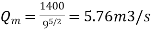
Case 2: hm=6cm=0.06m Qm=0.02m3/s
Discharge ratio Lr 2.5=Qp/Qm
Discharge of prototype Qp=Lr 2.5
Qm= (25)2.5×0.02=62.5m3/sec
Discharge perimeter length of prototype
=
∴Length of prototype=Width of prototype
=Lr×bm=25×0.5=12.5m
∴Discharge perimeter length of prototype
=62.5/12.5=5m3/sec
Q. In the model test of spillway the discharge and velocity of flow over the model were 2.1 m³/s and 1.6 m/s respectively. Calculate the velocity and discharge over the prototype which is 40 times the model size.
Given:
Model Qm=2.1m^3/s and Vm=1.6m/s, Lr= =40
=40
To find: Velocity and discharge over the prototype
Since the spillway, Froude number must be applicable using Froude number
Velocity scale ratio  =
=
∴Vp=6 =10.12m/s
Discharge scale ratio  =
= ^5/2
^5/2
∴Qp=2.1(40) ^5/2=21250.5m3/s
Q. A ship model of scale 1/60 is towed through sea water at a speed of 1.1 m/s. A force of 2.1 N is required to tow the model. Determine the speed of ship and the propulsive force on the ship, if the prototype is subjected to wave resistance only.
Solution:
 ∴Lr=50, Speed of model Vm=1.1m/s
Velocity scale ratio,
 =
=
∴ Vp= ( )×1.1=7.78m/s
Resistance to prototype in sea water
 =
=
Fp/2.1= (50)3
∴Fp=262.5×10^3N=262.5KN
References:
1.Hibbler, “Fluid Mechanics in SI units”1/e Pearson Education, Noida
2.Cengel & Cimbala, “Fluid mechanics” TMH, New Delhi
3.Katz, “Introductory Fluid Mechanics” Cambridge University Press
4.Pnueli & Gutfinger, “Fluid Mechanics” Cambridge University Press
5.Modi & Seth “Hydraulics & Fluid Mechanics” Standard Publication


