Unit - 1
Introduction to Surveying
Definition:
- Surveying is the art of determining the relative positions of different objects on the surface of the earth.
Importance of Surveying:
- The making plans and layout of all Civil Engineering initiatives inclusive of creation of highways, bridges, tunnels, dams and many others are primarily based totally upon surveying measurements.
- Moreover, for the duration of execution, challenge of any importance is built alongside the strains and factors set up with the aid of using surveying.
- Thus, surveying is a simple requirement for all Civil Engineering initiatives.
- Other major works wherein surveying is frequently utilised are:
- To repair the countrywide and kingdom boundaries;
- To chart coastlines, navigable streams and lakes;
- To set up manage factors;
- To execute hydrographic and oceanographic charting and mapping; and
- To put together topographic map of land floor of the earth.
Key Takeaways:
Surveying is the art of determining the relative positions of different objects on the surface of the earth.
Classification of Surveying:
There are two types of surveying:
Plane Surveying:
- The curvature of the earth is not taken into consideration.
- It is carried out for small area.
- Plane surveying is conducted by state agencies.
- It is carried out over an area less than 250 km².
Geodetic surveying:
- The curvature of the earth is taken into consideration.
- It is carried out for large area.
- Geodetic surveying conducted by survey of India Department.
- It is carried out over an area greater than 250 km².
Key Takeaways:
There are two types of surveying:
- Plane Surveying
- Geodetic surveying
Principles of Surveying:
The two-fundamental principle upon which various methods of plane surveying falls are:
1.Location of a point by measurement from two points of reference
- The relative position of a point to be surveyed is located by measurement from at least two points of reference, the positions of which have already been fixed.
- If P and Q are the two reference points on the ground, any other point, such as R, can be found by any of the direct methods. A single method is sufficient to locate the relative position of ‘R’ with respect to reference points P and Q, it is necessary to adopt at least any two methods to fix the position of point ‘R’.
2.Working from whole to part
- Here it is always desirable to carryout survey work from whole to part which means, when an area is to be surveyed then first a system of control points is to be established covering the whole area with very high precision. Then small details are located by less accurate methods.
- The idea of working this way is to prevent the accumulation of errors and to control and localize minor errors which would expand to greater magnitudes if the reverse process is followed, thus making the work uncontrolled at the last.
Survey Station:
Survey stations are the points at the start and the end of a chain line. They may also happen at any convenient points on the chain line. Such station may be:
1. Main stations.
2. Subsidiary stations. And
3. Tie stations.
1.Main Stations
- The stations taken along the boundary of an area as controlling points are known as ‘main stations. The lines joining the main stations are called ‘main survey lines.
2.Subsidiary Stations.
- The stations are on the main survey lines or any other survey lines are known as “subsidiary station”. These stations are taken to run subsidiary lines for dividing the area into triangles, for checking the accuracy of triangles and for locating interior details.
3.Tie Stations.
- Tie stations are also subsidiary stations taken on the main survey lines.
- Lines joining the tie stations are called tie lines.
- Tie lines are mainly taken to fix the directions of the adjacent sides of the chain survey map.
Base Line.
- The line on which the framework of survey is formed is known as the ‘base line’.
- It is most important line of the survey.
- The longest of the main survey lines is considered the base line.
- This line should be taken through fairly level ground, and should be measured very carefully and accurately.
Check Line.
- The line joining the apex points of triangle to some fixed point on its base is known as the ‘check line’. It is taken to check the accuracy of the triangle.
- Bearing of a line is the horizontal angle which a line makes with some reference direction also known as meridian.
Important definition:
- Reduced level: -elevation of any point with respect to mean sea level.
- Benchmark: -a fixed point on ground of known reduced level from where levelling work is started and reduced level of all other points are calculated with respect to reduced level of benchmark.
- Back sight: -first reading taken after setting up the instrument at any location.
- Foresight: -all least readings taken from any instrument location.
- Intermediate sight: -all other staff readings other than back sight/foresight
Survey lines:
- It is a line produced on a cast by a surveyor marking the contour in relation with planned path of placement of a restoration is known as survey line.
Chain lines:
- The lines joining the main stations are called main Survey or Chain lines.
Base Line:
- The line on which the framework of survey is formed is known as the ‘base line’. It is most important line of the survey.
- The longest of the main survey lines is considered the base line.
- This line should be taken through fairly level ground, and should be measured very carefully and accurately.
Check Line:
- The line joining the apex points of triangle to some fixed point on its base is known as the ‘check line’. It is taken to check the accuracy of the triangle.
- In surveying, the gap among factors way the horizontal distance. If the factors are at distinctive elevations, then the gap is the horizontal period among plumb traces on the factors.
- The line among a and an arbitrarily selected reference line. When the reference line is north or south and the perspective is certain east or west, the route is known as “bearing.” When the reference line is south and the perspective is clockwise, the route is known as “azimuth.”
- When the peak of a factor is its vertical distance above or underneath the floor of a reference aircraft* you've got selected, it's far known as the elevation of that factor. When the peak of a factor is its vertical distance above or underneath suggest sea level (because the reference aircraft), it's far known as the altitude* of the factor.
- It is the process of establishing intermediate point on a straight line between two end points.
- There are two methods of ranging.
1) Direct ranging.
2) Indirect ranging or reciprocal ranging
- Direct method: when intermediate ranging rods are fixed on a straight line by direct observation from end stations, the process is known as direct ranging
- Indirect ranging method: when the end station is not intervisible due to being high ground between them, intermediate ranging rods are fixed on the line in an indirect way this method is known as indirect ranging.
Key Takeaways:
The process of establishing intermediate points on a straight line between two end points is known as ranging
Meridians:
- The reference line with respect to which horizontal angle of survey line is measured, known as meridian.
Types of meridians:
a) True Meridian: The line or length passing through the geometrical north pole, geographical south pole and any point on the earth surface is known as true meridian.
b) Magnetic Meridian: It is the direction indicated by freely suspended and balanced magnetic needle unaffected by local attractive forces. The location of magnetic pole is continuously changing hence, the direction of magnetic also changes.
c) Arbitrary Meridian: It is any convenient direction usually from survey station to some well-defined permanent object. This is used for small area survey or to determine the relative direction of small traverse.
Key Takeaways:
There are three types of meridians:
- True meridian
- Magnetic meridian
- Arbitrary meridian
Bearings:
- The horizontal angle made by a survey line with reference to magnetic north pole in a clockwise direction is called as the bearing of a line.
Types of bearings:
- Generally, the bearings of survey lines are designated in the following two types:
- Whole circle bearing (W.C.B.) system
- Reduced bearing (Quadrantal) system
1. Whole circle bearing (W.C.B.) system:
- When the bearing of a line is measured with respect to magnetic north in clockwise direction, it is called as magnetic bearing or whole circle bearing.
- The value of W.C.B. Varies from 0° to 360°.
- Four quadrants I, II, III and IV are shown in Fig.
- The W.C.B. Of a line OA in the first quadrant is
 (
( between 0° to 90°).
 - The W.C.B. Of a line OB in the second quadrant with respect to north is
 (
( between 90° and 180°) W.C.B. Of a line OC in the third quadrant with respect to north is
 (
( between 180° and 270°) and W.C.B. Of a line OD in the fourth quadrant with respect to north is
  , (
, ( between 270° and 360°).
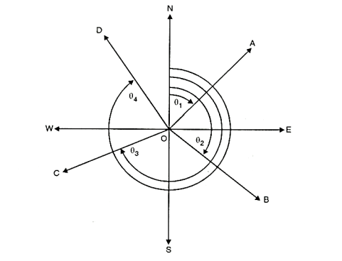
Fig 1: Whole Circle bearing
2. Reduced bearing (Quadrantal system):
- In reduced bearing, the bearing of survey lines is measured with respect to north and south line either in clockwise or anticlockwise direction towards east or west.
- Fig. Shows quadrantal bearing system.
- Any line in any of the four quadrant is expressed by an angle which is measured from either north or south.
- The directions are essentially written before and after the value of angle.
- This helps to identify in which quadrant the lines lie. The maximum bearing in such case is 90°.
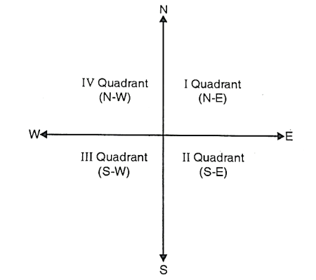
Fig 2: Quadrantal bearing
Key Takeaways:
Generally, the bearings of survey lines are designated in the following two types:
- Whole circle bearing (W.C.B.) system
- Reduced bearing (Quadrantal) system
There are two Methods of Levelling:
1. Height of collimation method
2. Rise and fall method
1.Height of Collimation method:
- In this method, the reduced level of collimation plane or height of instrument is determined for each set up of dumpy level and then reduced levels (R.L.) of the other points are found out with respect to the plane of collimation or height of instrument.
Level page of the field book
Staff Station | B. S | I.S | F. S | H.I (Collimation plane level) | R. L | Remarks |
B.M |
|
|
|
|
|
|
1 |
|
|
|
|
|
|
2 |
|
|
|
|
|
|
3 |
|
|
|
|
|
|
Procedure:
- Step 1: To prepare the format of level page before levelling work start:
For entering the readings of reduced level of different sights, the following format of level page is commonly used into practice.
- Step 2: To find the height of instrument (H.I.) or R.L. Of plane of collimation:
Keep the levelling staff on bench mark (B.M.) and take reading and find the reduced level of collimation plane or height of instrument by adding back sight reading to the R.L. Of bench mark.
Note that, Height of instrument is equal to R.L. Of collimation plane.
Height of instrument (H.I.) = R.L. Of bench mark + B.S. Reading.
- Step 3: To find R.L. Of intermediate points or change points:
Reduced level of intermediate points can be found out as follows:
R.L. Of intermediate points =Height of instrument - Intermediate sight reading
=H. I-. I.S. Reading
R.L. Of change point =Height of instrument - Fore sight reading
= H.I. - F.S. Reading
Note: When levelling work is to be stopped or change point is to be taken, then foresight reading is taken.
- Step 4: To find new height of instrument or new plane of collimation:
The instrument is shifted and set up and levelled at new position so that reading on levelling staff would be clear and distinct. Then take back sight reading on change point (C.P.) and find the R.L. Of new collimation plane or new height of instrument. Refer to Fig.
R.L. Of new height of instrument =R.L. Of change point + B.S.
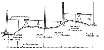
Fig 3: H.I Reading method
- Step 5: To find reduced levels of the remaining points:
Find the reduced levels of the remaining points from new set up of instrument with respect to new height of instrument or new R.L. Of collimation plane.
- Step 6: To finish the levelling work:
Repeat the above procedure till all the levelling work is over.
- Step 7: To find arithmetical check:
After completion of levelling work, arithmetical check is found out. From this check. Accuracy of the field work of levelling can be cross-checked. This check can be taken at each level page.
- Arithmetical check:
Sum of backsights - sum of foresights =Last R.L. - First R.L.
In short,  . -
. -  .= Last R.L. - First R.L.
- Note: It is noted that the arithmetical check can be taken at each level page.
The Rise and Fall method:
- In this method, instead of H.I. Column in the format of level page, two columns of rise and fall are introduced for calculation of R.L's. Difference of levels between consecutive points is found by comparing the staff readings on the two points for the same setting the instrument.
Rise and fall method is stepwise explained as follows:
- Step 1: Prepare the format of level page before levelling work start, as shown below:
Level Page of field book
Staff Station | B. S | I.S | F. S | Rise | Fall | R. L | Remark |
B.M |
|
|
|
|
|
|
|
A |
|
|
|
|
|
|
|
B |
|
|
|
|
|
|
|
C |
|
|
|
|
|
|
|
. |
|
|
|
|
|
|
|
. |
|
|
|
|
|
|
|
- Step 2: The difference in staff readings between the consecutive points is found out.
- Step 3:
- If the staff reading of second point in level page is higher than the first, then it indicates fall which is then to be subtracted from R.L. Of previous point.
- If the staff reading of second point in level page is lower than the first one, then it indicates rise which is further to be added to the R.L. Of previous point.
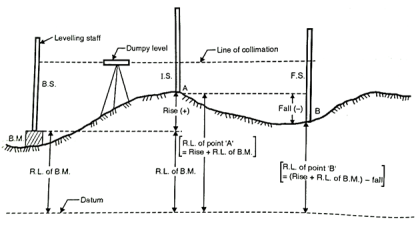
Fig 4: Rise and fall method
- Step 4: Repeat the same procedure till the levelling work is over.
- Step 5: After completion of levelling work, the arithmetical check is found out, which shows accuracy and cross check of the field work in levelling. Note that, the check can be taken at each level page and on R.L., of every intermediate points.
- Arithmetical check:
Sum of backsights - sum of foresights = Sum of all rise- sum of all= Last R.L. - First R.L.
In short, Σ B.S. -  . = Rise-fall=Last R.L – First R.L
- Note: It is noted that arithmetical check can be taken on R.L. Of intermediate points.
- In this method calculation work is more, therefore it is tedious but there is check on every point; hence it is accurate method rather than H.I. Method.
Height of Instrument method:
Staff Station | B. S | I.S | F. S | H.I (Collimation plane level) | R. L | Remarks |
B.M |
|
|
|
|
|
|
1 |
|
|
|
|
|
|
2 |
|
|
|
|
|
|
3 |
|
|
|
|
|
|
Arithmetic Check:
ΣBS – ΣFS = LRL-FRL
Rise and Fall Method:
Staff Station | B. S | I.S | F. S | Rise | Fall | R. L | Remark |
B.M |
|
|
|
|
|
|
|
A |
|
|
|
|
|
|
|
B |
|
|
|
|
|
|
|
C |
|
|
|
|
|
|
|
. |
|
|
|
|
|
|
|
. |
|
|
|
|
|
|
|
Arithmetic Check:
ΣBS-ΣFS =LRL-FRL=
If the level is placed exactly midway between two points and staff reading are taken to determine the difference of level then an error is automatically eliminated but here in the case of a river or valley, it is not possible to set up the level midway between two points on the opposite bank so, the method of reciprocal levelling is adopted.
In reciprocal levelling, the level is set up on both bank of the river or valley and two sets of staff reading is taken by holding the staff on both banks in this case it is found that error is completely eliminated and true difference of level is equal to the mean of the two apparent differences of level.
Procedure:
1. Suppose A and B are two points on an opposite bank of a river. The level is set up very near A and after proper temporary adjustment staff reading are taken at A and B. Suppose reading a1 and b1
2. Level is shifted and set up very near B and after proper adjustment, staff reading is taken as A and B. Suppose the reading are a2 and b2
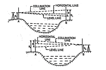
Fig 5
Let,
h= true difference of level between A and B
e= combine error due to curvature, refraction and collimation
(Error is +ve and –ve, here error is assumed +ve)
First case:
Correct staff reading A=a1
Correct staff reading B=b1 – e
True difference of level between A and B
h= a1 – (b1-e) ……………………………………………………..eq.1
Second case:
Correct staff reading B=b2
Correct staff reading a=a2 – e
True difference of level between A and B
h= (a2 - e) – b2 ……………………………………………………..eq.2
From (1) and (2)
2h= a1 – (b1-e) + (a2 - e) – b2
2h= a1 – b1 + e + a2 – e – b2
2h= (a1 – b1) + (a2 – b2)
h= [(a1 – b1) + (a2 – b2)] / 2
Levelling
Levelling may be defined as the art of determining the relative height or elevates of points or objects on the earth’s surface.
Instruments used for levelling:
Level
Levelling Staff
Level: The purpose of a level is to provide a horizontal line of sight.
Parts:
A telescope to provide line of sight
A level tube to make the line of sight horizontal
Levelling head to bring the bubble in its centre of run
A tripod to support the instrument
Dumpy level:
The telescope is fixed with the support and therefore, can neither be rotated about the longitudinal axis, or can it be removed from its support. A long bubble tube is attached at the top of the telescope. The levelling head generally consists of two parallel plates with either three-foot screw of four-foot screws. The upper plate is known as tribrach and the lower plate is known as trivet which can be screwed on a tripod.
Levelling staff:
- A levelling Staff is a straight rectangular rod having graduations, the foot of the staff representing zero reading.
- One is Folding type of 4m Levelling Staff:
- It consists of two wooden pieces each of 2m of length with the joint assembly. The thickness and width of staff are respectively 18m and 75mm. The folding joint is of the detachable type with locking device at the back.
- Hence the stand can be made into two parts for easy handling. When two pieces are locked together, the two pieces form a straight rigid levelling staff of length equal to 4m.
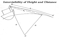
Fig 6
The maximum distance on ground that is visible to a person at certain height is called distance of visible horizon.
If there is no effect of refraction: -


 h=in meter, d=in km
Profile leveling:
The process of determining the elevations of points at measured intervals along a fixed line such as the centre line of a railway, highway, canal or sewer is known as profile levelling.
Objects: To determine the undulations of the ground surface along a given line for the alignment of canal, pipe line, road and railway.
Field procedure:
- Let PQR be the given line of section.
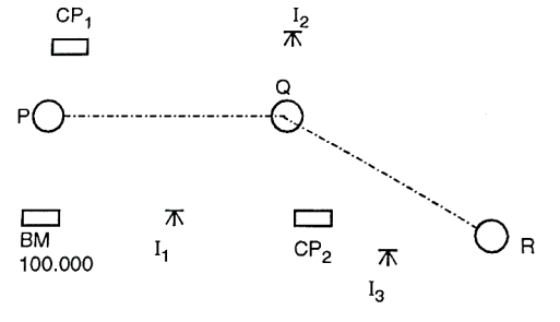
Fig 7: Profile leveling
2. Mark point at 10 m intervals on this line.
3. Level is set up on a firm ground at a suitable point I1
4. Temporary adjustment of level is done and B.S is taken on the B.M.
5. The RL of collimation (HI) is worked out by adding B.S. To the R.L. Of B.M. The chain is stretched from P toward the point B.
6. Also, the staff readings are taken at 10 m points, and entered in the I.S column against the respective chainages.
7. Besides these points, the staff readings are taken at the representative points for example slope of ground surface changes appreciably.
8. When it is found necessary to shift the instruments on account of the length of sight exceeding about 100 m or the further points not being possible to be observed owing the irregularities of the ground, CP, is taken at suitable position, and F.S is taken on it and entered in F.S column.
9. The instrument is then shifted and set up on firm ground at I2, as before.
10. B.S is taken on CP1, and new HI is calculated.
11. Chaining and readings are then continued as before until the reading is obtained at the last point R.
12. B.M should be checked during the progress of the work.
13. Therefore, bearing of the line PQ, QR etc are taken with compass at start and noted in the field book.
14. Neat sketches of Bench Marks and the features such as nalla, road crossing etc should be drawn in the field book with full description.
Important points to be remembered while running a profile:
- The chainage of the staff points is continuous from the beginning to the end of the section line.
- To eliminate the instrumental errors, the back sight and fore-sight distance should be approximately equal.
- Bubble must be in the centre of its run when the B.S and F.S readings are taken.
- The features such as Road, Foot path, nalla, river etc crossed by the line should be fully located by taking bearing of their centre lines, their width or by offsets.
Plotting Profile Levelling:
- When the heights of all the points along the section have been calculated, a profile can be drawn.
- The horizontal distance is plotted along the horizontal axis to some convenient scale and the distances are also marked. The vertical lines are drawn at these points representing the elevations above the reference level. Each ground point is thus plotted by two coordinates i.e., chainage and elevation. The line joining the top points of these ordinates then represents the ground sections.
- Since the horizontal distances involved are in general very much greater than the variations in level. Thus, y axis scale is larger than the x axis. In this way irregularities of the ground are made more apparent. The ratio of exaggeration adopted runs from 5 to 15 times.
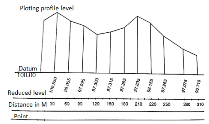
Fig 8: Plotting profile level
Cross Sections:
- The lines of cross-sections are in general perpendicular to the longitudinal section line.
- The purpose of cross sectioning is to furnish the engineer with sufficient information regarding the levels of the ground on either side of the longitudinal section to enable him to design the intended work. Cross-sections are taken at every 20 m or 30 m distance along the centre line. The length of cross-section may be run at closer intervals to outline the features of road, nala, etc. Electro refining
- The cross sections are numbered consecutively from the commencement of the centre line and are set out at right angles to the main line of section with the chain and tape, the cross-staff or the optical square and the distances are measured left and right from the centre peg. The length of cross-section depends upon nature of work Refer Fig.
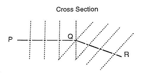
Fig 9: Cross-section
Plotting the Cross Section:
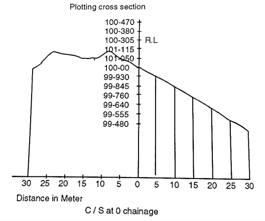
Fig 10: Plotting cross section
- The plotting of cross sections observed as above is similar to that of profiles, except that, in this case vertical and horizontal measurements plotted to the same scale.
- The point along the longitudinal section is plotted at the centre of the horizontal axis.
- The points to the left of center are plotted to the left and those to the right are plotted to right. The points so obtained are joined by straight lines.
Key Takeaways:
Profile leveling: The process of determining the elevations of points at measured intervals along a fixed line such as the centre line of a railway, highway, canal or sewer is known as profile levelling.
Cross Sections: The lines of cross-sections are in general perpendicular to the longitudinal section line.
There are following types of Errors in Levelling: -
- Instrumental Errors
- Collimation Error
- Error due to Curvature & Refraction
- Other Errors
1. Instrumental error and Correction:
- Collimation error
- Correction: Check before use and equalise sights.
- Under sensitive bubble.
- Errors in staff graduation
- Correction: Check
- Loose tripod head.
- Telescope not parallel to bubble tube
- Correction: Permanent adjustment.
- Telescope not at right angles to the vertical axis
- Correction: Permanent adjustment
2. Error of Collimation
Collimation error occurs when the collimation axis is not truly horizontal when the instrument is level. The effect is illustrated in the sketch below, where the collimation axis is tilted with respect to the horizontal by an angle a.
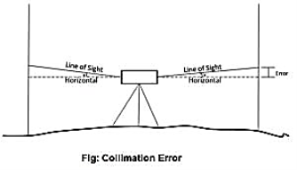
Fig 11
3. Curvature & Refraction
Curvature of the earth:
The earth appears to “fall away” with distance. The curved shape of the earth means that the level surface through the telescope will depart from the horizontal plane through the telescope as the line-of-sight proceeds to the horizon.
This effect makes actual level rod readings too large by:

Where D is the sight distance in thousands of feet.
Effects of Curvature are:
- Rod reading is too high
- Error increases exponentially with distance
Atmospheric Refraction:
Refraction is largely a function of atmospheric pressure and temperature gradients, which may cause:
The bending to be up or down by extremely variable amounts.
The atmosphere refracts the horizontal line of sight downward, making the level rod reading smaller. The typical effect of refraction is equal to about 14% of the effect of earth curvature.
Combined Effect of Curvature and Refraction in Survey
The combined effect of curvature and refraction is approximately

The formula for computing the combined effect of curvature and refraction is:
C + R = 0.021K2
Where C = correction for curvature
R = correction for refraction
K = sighting distance in thousands of feet
4.Other sources of errors in levelling and their correction:
Type of Error | Correction |
1. Incorrect setting-up of instrument. |
|
2. Movement of staff from position when changing level station. |
|
3. Staff not held vertically. |
|
4. Parallax: Instrument knocked or moved during backsight-foresight reading |
|
5. Ground heating causes chaotic refraction of light |
|
6. Tripod or rod settles between measurements e.g., Bubble off center |
|
Methods of Plane Table Surveying:
Generally, there are four methods available to perform plane table surveying. They are
- Radiation
- Intersection
- Traversing
- Resection
Radiation:
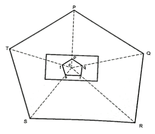
Fig 12: Resection Method
Procedure:
- Select an instrument station C from which all the points to be surveyed are visible.
- Set up and level the board and clamp it.
- Select a point C, on the sheet to represent the instrument station.
- Draw the direction of the magnetic meridian with the help of trough or circular compass in the top corner of sheet.
- With alidade touching C, sight various points P.Q.R.S.T etc. to be located, draw rays towards them
- Measure the distance CP, CQ, CR, CS, CT etc. and plot them to scale and join the points pqrst so obtained.
Use:
- This method is used for small area which can be commanded from a single
- This method is employed in combination with some other method.
Intersection method:
- In intersection method the point is fixed on plan by the intersection of the rays drawn from the two instrument stations.
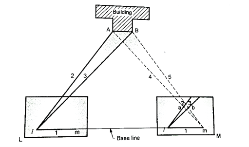
Fig 13: Intersection method
Procedure:
- Select two points L and M in a commanding position.
- The line joining the station L and M is known as base line.
- Measure the base line LM.
- Set up the table at the sta L and mark point I on sheet over L.
- Orient the board by placing alidade along Im and turn the board until the ranging rod at B is bisected. Clamp the board.
- With alidade touching point I draw rays 1, 2, 3 of indefinite length as shown in Fig.
- The table is then shifted to station M, orient it by back sighting method on L.
- Through m draw rays towards the point previously sighted i.e., 4, 5 are drawn determine the points on intersection a and b.
Use:
The intersection method is used for:
- Locating details of area.
- For locating distant and inaccessible points, broken boundaries, bank of river etc.
- For plotting position of points to be used subsequently as the instrument stations.
- It is suitable when it is difficult or impossible to measure distance as in the case of the survey of mountainous country.
Traversing Method:
- In this method the instrument is shifted from one station to another.
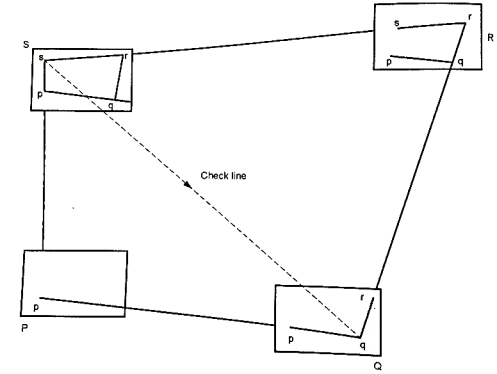
Fig 14: Traversing Method
Procedure:
- Set up the instrument at station P. Select the point 'p' on the sheet. Center and level the table when the board is clamped.
- Mark direction of magnetic meridian on sheet by trough or circular compass.
- Touching the alidade on 'p' sight the ranging rod at Q and draw a ray.
- Measure the distance PQ with chain or tap and lay it off to scale on the ray drawn towards Q. Thus, fixing the position of q on the sheet.
- Shift the instrument and set up at Q, orient it by any method on P with the alidade along qp and then clamp the table.
- With the alidade touching q, sight the station R and draw a ray.
- Measure the distance QR and lay it off to scale on the ray drawn towards R to fix the point r on the sheet.
- The nearby details are also located as usual.
- Proceed the traverse until all the stations are plotted.
- At any station the work can be checked by taking sights to two or more proceeding stations visible from the station occupied.
Uses:
Traversing method is used:
- For running survey lines between the stations previously fixed by any method.
- To locate the topographical details.
- For survey of roads, rivers etc.
Resection Method:
- Only the instrumentation stations established by this method.
- After fixing the stations, details are located either by radiation or intersection.
Procedure:
- As in the intersection method select a base line AB on the ground.
- With the help of tape, measure it accurately and plot it to scale on the sheet as 'ab' in a suitable position.
- Set up the table at A. Centre it so that A is exactly over A and then level it accurately.
- Place the alidade along AB, then orient the table until ranging road at B is bisected and then clamp it.
- With the alidade touching A, sight the station C which is to be located by resection and draw a ray along the ruling edge of the alidade. Mark the point 'c' along the rays by estimation.
- Shift the table to point C such that 'e' is over C. Orient the table by back sight at point A and clamp it.
- Place the alidade against b and sight B where the edge of alidade cuts (resects) draws a ray. The point of intersection of this ray and that preciously drawn from A gives the required point c.
- Continue the process to establish the other station points.
- The above explained method is also called as back ray method as it necessary to draw a ray from the preceding station to the station to be occupied by the plane table.
- Errors in centering though inevitable, it will not affect the accuracy of the work as it is only used for small work.
- Details are best located by radiation or intersection.
Key Takeaways:
Methods of plane table surveying are as follows:
- Radiation Method
- Intersection method
- Traversing method
- Resection method
Areas and volumes
- Contouring in surveying is the dedication of elevation of numerous factors at the floor and solving those factors of equal horizontal positions withinside the contour map.
- To exercising vertical, manage leveling paintings is accomplished and concurrently to exercising horizontal manage chain survey or compass survey or aircraft desk survey is to be accomplished.
- If the theodolite is used, each horizontal and vertical controls may be performed from the equal instrument.
- Based at the units used one could classify the contouring in unique groups.
Characteristic of Contour:
- The contour lines have the following characteristics
- All points on a contour line have the same elevation or R.L's. Fig. Shows the contour lines of equal elevation.
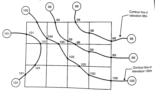
Fig 15: Contour lines of same elevation
- Two contour lines of different elevations cannot cross each other. However, in case of overhanging cliff two contour lines of different elevations can intersect. For such case, refer the Fig.
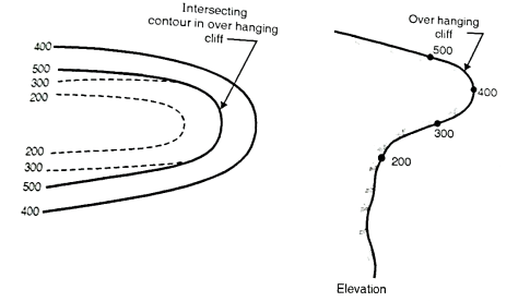
Fig 16: Intersecting contours in overhanging cliff
- Steeps slope:
(i) When contour lines come close together then it indicates steep slope. Fig. Shows steep slope along X-X.
(ii) Uniform slope: if contour lines are equally spaced, uniform slope is indicated.
(iii) A series of straight, parallel and equally spaced contours represent a plane surface.
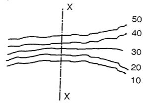
Fig 17: Steep slope along X-X
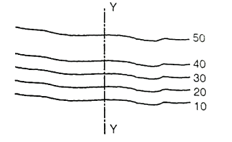
Fig 18: A gentle slope along Y-Y
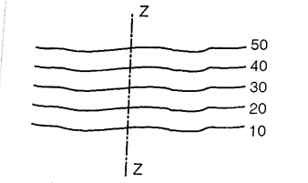
Fig 19: Uniform slope along Z-Z
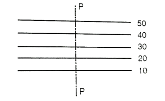
Fig 20: Plane surface slope along P-P
- Hill: Closed contour lines with higher values inside indicate hill. See Fig.
Depression: Closed contour lines with lower values inside indicate a depression.
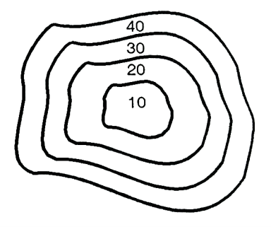
Fig 21: shows depression
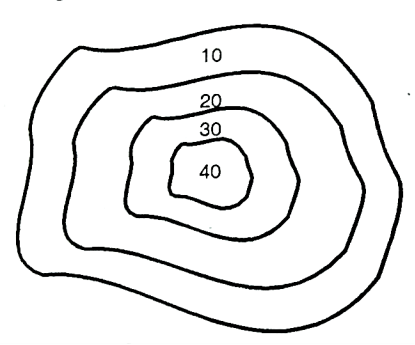
Fig 22: Shows a hill
- Ridge line:
Fig. Indicates a ridge line. Contour lines cross ridge at right angles. For ridge line the higher elevation contour is inside the loop or band.
Valley line
Fig. Indicates a valley line. Contour lines also cross the valley lines at right angles. Valley line is indicated by higher elevation contours outside the loop.
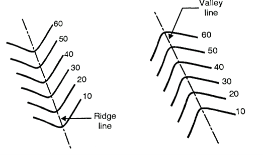
Fig 23: Ridge and valley line
Methods of Contour Surveying
There are two methods of contour surveying:
- Direct method
- Indirect method
Direct method:
- In the direct method, the contour to be plotted is actually traced on the ground.
- These points are plotted on ground and contours are marked through them. This method is followed where great accuracy is required.
Procedure:
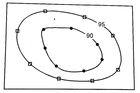
Fig 24: Direct method
- Consider an area as shown in Fig. Which is to be surveyed for contouring.
(a)The work is started from B.M. And level is setup at the centre of the area.
(b) Suppose it is required to find out the contour of 90.000 m then the staff should be moved to various positions on plot where the reading on staff should give R.L. Of 90.000 m. On ground. When all the points are located, they are marked on ground directly.
(c) Similar process is followed for locating the contour of 95.000 m and other contours.
Indirect method:
- In this method spot levels are taken at regular interval along predetermined lines on the ground. The work is then plotted on plan and then the required contour lines are drawn by the process of interpolation.
- The indirect method is less tedious and speedy as compared to direct method.
- The methods followed in indirect method of contouring are:
(a) By cross-section:
- This method is suitable for roads, railways and canal survey. Consider X, Y, Z as the centre line of the road or railway or canal route as shown in Fig. Cross sections are set at every 10 m on the centre line whereas the other dimension to complete a rectangle may be 5 m.
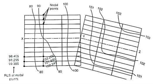
Fig 25: Method of cross-sections
- The spacing of the cross-section depends upon the nature of terrain. The cross-sections are more closely spaced where the contours curve abruptly. Staff readings of all the nodal points are determined and the R.L's are calculated. The same cross-section is plotted on the sheet to a suitable scale. The respective R.L's are written on the nodal point as shown in Fig. And then the required contours are interpolated between the R.L's.
(b) By squares:
- In this method the area to be surveyed is divided into a number of squares of size 5 to 20 m depending upon the nature of the ground and contour interval required. The elevations of the corners of the squares (called nodal points here) is determine by means of process of levelling. The calculated reduced level of these nodal points are then written on the respective nodal and contours are interpolated between them.
- This method is used when the area to be surveyed is small and the ground is not mush undulating because on undulating ground it would be practically impossible to form squares.
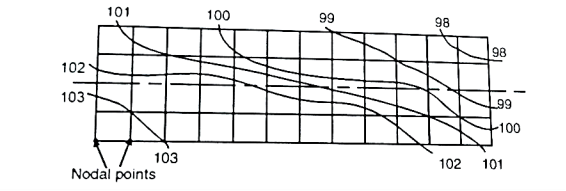
Fig 26: Method of square
(c) By tacheometric method:
- In the case of hilly areas, tacheometric contouring method is used. Here instrument known as tacheometer which is a theodolite, is utilized which determines horizontal distances and elevation of points.
- As shown in Fig. The tacheometer is set at a point approximately at the centre of the area. Radial lines are set making angles with either the magnetic meridian or with the first radial line. On each radial line staff readings are observed at different points. When the readings along all the radial lines have been observed, it is then plotted on a sheet to a suitable scale. The required contour lines are then interpolated as usual.
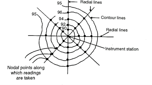
Fig 27: Tacheometric method
Key Takeaways:
Direct method: In the direct method, the contour to be plotted is actually traced on the ground.
Indirect method: In this method spot levels are taken at regular interval along predetermined lines on the ground. The work is then plotted on plan and then the required contour lines are drawn by the process of interpolation.
Uses of Contour maps:
The important uses of contour maps are:
Intervisibility between two points:
- A contour map can be used to determine the intervisibility of two points knowing the elevations of two stations at a farther distance. If a contour line passes in between them of more elevation then the stations will not be intervisible.
Calculation of reservoir capacity:
- The contour plan used to calculate the storage capacity of reservoirs. The areas between the contours are found by planimeter and multiplied by contours interval, will give the total volume of water that can be stored in a reservoir.
Drawing of sections:
- If a contours plan is given and a section is drawn along any direction, the general shape of the ground can be known.
- Fig. shows section of line PQ.
Location of Route:
- A contour plan is very much useful in locating the route of a highway, railway, canal or any other communication line Fig. Show route P to Q at an upward gradient.
Key Takeaways:
- Intervisibility between two points
- Calculation of reservoir capacity
- Drawing of sections
- Location of Route
Computation of areas and volumes:
Area
- Trapezoidal rule: -
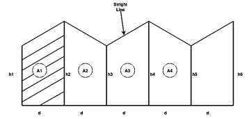
Fig 28
Area 

Total area =A = d (
2. Simpson's rule: -
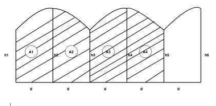
Fig 29


Total area=A=
We need odd number of offsets.
If even number of offsets.
One area is calculated by trapezoidal formula and added with remaining area, calculated by Simpson’s formula.
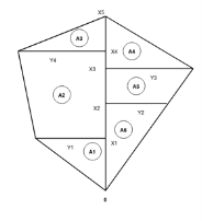
Fig 30


.
.
.
Total A =?
Volume
If parallel areas at equal interval are available (or can be found)
1.Trapezoidal formula

2.Simpson's Formula: -

Theodolite survey:
- It is precise instrument for measuring angles in the horizontal and vertical planes.
- It is accurate method or instrument used for measuring horizontal and vertical angles.
- It can use in prolonging survey lines, and finding elevations etc.
- It is also used for levelling.
- The line of sight of instrument can be rotated 180 degrees in vertical plane about its horizontal axis.
Instruments:
Following are part of theodolite:
(1) Telescope
- Telescope in theodolite is used for focusing at which object piece and eye piece at other.
- It rotates about horizontal axis in vertical plane.
(2) Vertical circle
- It is fitted to telescope and more simultaneously.
- Graduation is there in each quadrant from 0 to 90 degree.
(3) Index frame
- It is also known as Vernier frame or t frame.
- It consists of two parts vertical and horizontal.
- Horizontal arm is used to measure Vertical angle.
- Vertical arm Culp’s to lock telescope at certain level.
(4) Standards
- They are the frames which support telescope and it is rotated about vertical axis.
- It is also called as A frame.
(5) Upper plate
- It gives support to standards.
- It consists of two Vernier with magnifiers which are arranged diagonally.
- Upper clamping screw with respect to tension screw which helps to fixing with the lower plate.
(6) Lower plate
- It contains scale on which 0 to 360 reading are graduate.
- It is also called as scale plate.
- It is attached to outer spindle.
- It consists lower clamping screw.
- If lower clamp is loosened and upper is tightened both plates can rotate together.
- if the procedure is reversed that is lower clamp is tightened and upper loosened and then upper plate is movable and lower plate is fixed.
7) Levelling head
- It contains two parallel triangular plates known as tri batch plates.
- Upper path that is upper tribrach used to level up per plates and telescope with help of levelling screw.
- Lower part i.e., lower tribrach plate and is attached through tripod.
8) Shifting head
- It contains two parallel plates which are right angle to each other with one of them is parallel to trunnion axis.
9) Tripod: -
- It is just stand for theodolite which mounted over it.
- Levelled position is required for tripod to give correct observations.
- Steel shoes are there at the end of tripod leg.
- These legs hold the ground strongly
10) Plumb Bob
- It is cone-shaped weight attached or tie with long thread.
- These is used for entering of theodolite.
11) Magnetic compass: -
- It is in circular compass box in centre of upper plate and used for selecting meridian.
Measurement of horizontal and vertical angle
a) Horizontal angle: -
- Horizontal angle are used to find bearing and direction in control survey.
- It is also used for locating detail when mapping.
b) Vertical angle: -
-It is used to find out the height of points and to calculate slope connections.
Measurement of horizontal angle
1) To measure angle of ABC, instrument is set to B.
2) Upper clamp is loosened and lower clamp is fixed.
3) Telescope is turned and Vernier A is a set O and Vernier B to 180°.
4) Now lower clamp is loosened and tightened scope is pointed to A and bisect ranging rod at A.
5) Now lower clamp is tightened and lower tangent screw is turned to perfectly bisect ranging rod at A.
6) Now upper clamp is loosened and telescope is turned clockwise to bisect the C which is tightened at upper clamp.
7) Now, Vernier reading A and B is noted.
8) Vernier A result in angle directly and Vernier B result reading by subtracting initial reading from final reading.
Measurement of vertical angle
1) The zeros of Vernier are set to 0 degree to vertical circle.
2) Telescope is den clamped.
3) Plate bubble are brought to center with foot screw and altitude bubble is brought to centre by clip screw.
4) Telescope in bisect to point A and measure the angle of elevation.
5) Finally reading of Vernier is noted and elevation angle is also noted.
6) Now, face of instrument is changed and point A is bisected again and reading are noted.
7) Telescope is lowered slowly and B is bisected to measure angle of depression.
Horizontal and vertical control:
Horizontal and vertical control are formed to create framework around other surveys can be adjusted.
Horizontal and vertical control surveys are used in accurate mapping projects in the construction of underground utility systems, and in roadways, power lines, tunnels.
Methods of horizontal and vertical control
Horizontal positioning | Vertical positioning |
a) Triangulation | a) Geodetic levelling |
b) Trilateration | b) Trigonometric heighting |
c) Traversing | c)Barometric levelling |
d) Astronomical positioning |
|
e) GPS |
|
Triangulation network
It is a network of triangles used to find the distance and position of point.
Network is done by measuring length of one side of a triangle and reducing its angle and length of other two sides by observation from baseline.
Figures or systems
The Survey System is the maximum whole survey software program package deal to be had for all varieties of questionnaires and studies tasks from web, phone, PDA, or paper questionnaires. This top-notch survey software program package deal is good for mixed-mode surveys, which integrate or extra of these methods.
Signals
- It is small device which is used to define location of triangulation station such that it is easily observed from other stations.
- Signal must be vertical over station.
- It is placed centrally over station mark.
- It is important to place over station mark because accuracy of triangulation system depends on signal that is entering of signal.
Signal: -
1) Opaque signal
2) Luminous signal
a) Opaque signal: -
- Is type of signal used where less accuracy and for short sight distance (i.e., not more than 30 kilometre)
- It must be used in day time only.
- Cheaper than luminous signal.
Example of opaque signal
1) Target signal – suitable for distance up to 30 km
2) Pole signal- distance up to 6 km
3) Elevated signal – elevated tower is used as signal and suitable for distance up to 30 to 40 km.
4) Stone signpost
5) Pole and brush signal
b) Luminous signal: -
- This type of signal basically used for geodetic survey because of quite distinct and have clear visibility even for long distance (more than 30 km).
- It is used for day as well as night also.
Luminous signal:
- Sun signal
- Light signal
(i) Sun signal - also known as heliotrope. Heliotrope reflects sun rays towards station.
(ii) Night signals - observation is at night. E.g., Drummond's light and magnesium lamp with parabolic reflector.
Satellite station:
- It is also known as eccentric station.
- Satellite station is a false station because it is not possible to set the instrument over the structure false station point is assumed.
- It is also a place where movement of satellite is followed and receive information from them.
Baseline and its importance
- A baseline survey is a look at this is completed at the start of an undertaking to gather statistics at the fame of a subject (something from crop yields to delivery weights) earlier than any sort of intervention can have an effect on it
- It affords a reference factor for monitoring the undertaking's progress; this is, to degree the diploma and nice of alternate all through an activity's implementation. Baseline surveys offer quantitative statistics on how a trouble influences unique corporations withinside the studies population.
Corrections
Chain / Tape corrections:
1)Correction due to standardization
Correction per chain length


Total correction

True length of line
Alternate solution of Q → (1)
Core (1) L = 30m and' = 30.40 m
1) C' = L'-L = 30.40-30 = (+) 0.40m
2) Number of chains = n = 
3) Total correction
 = 42.3×0.40= (+)169.20
4) Total length
l = 12690+169.20 = 16459.2 m
1) Correction due to slope
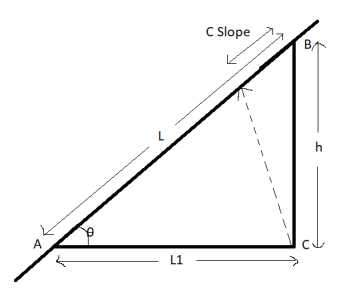
Fig 31
This correction is always a negative correction.
Correct distance between any two points on ground is horizontal distance.
Correction required = L – 

 approximate formula
If  angle is given

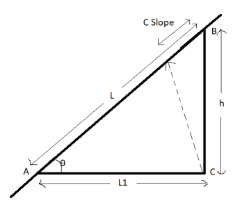
Fig 32

2) Correction due to wrong alignment
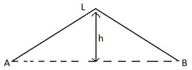
Fig 33
Same as slope correction
If endpoint of chain is not put on the straight line between points to be measured


Correction is always negative.
3)Temperature correction
If  is the temperature at the time of standardization.
 is the temperature at the time of measurement
L = length of chain / tape
 = Coefficient of thermal expansion

| Length of chain | Noted down value | Error | Correct |
 | Increase | Less | Negative | Positive |
 | Decrease | More | Positive | Negative |
5) Pull correction
 = value of pull applied at the time of standardization
 value of pull applied at measurement
L = length of chain / tape
 Cross sectionarea of tape
E = Young's modulus
Pull correction = 
| Error | Correction |
 | Negative | Positive |
 | Positive | Negative |
6) Sag correction
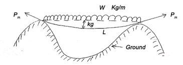
Fig 34

This collection is always negative.
Formal tension
The value of pull 
For which positive pull correction is exactly equal to negative sag correction is called normal tension.

Case (1) if horizontal distance up to the point can be mean.
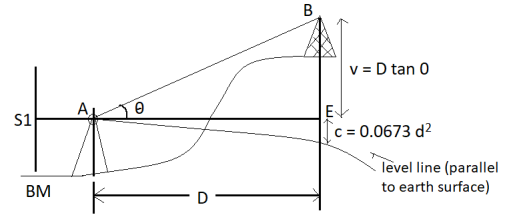
Fig 35
Given values: -
1) Distance 'D'
2) Angle=
3) Staff reading 
Vertical height
V = D tan
R.L. Of B = RL of B.M. + 
C= combined correction due to Earth curvature/ refraction
= (+) 0.0673  [positive for RL]
Case (2) If distance D cannot be measured
Given (known) values: -
1) Distance 'B' = AB
2) Staff readings 
Difference of staff readings 
3) Angle measured
From 
From 
4) RL of BM
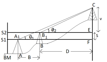
Fig 36

V+S=(B+D) tanθ1 (1)


RL of 
References:
1) Madhu, N, Sathikumar, R and Satheesh Gobi, Advanced Surveying: Total Station, GIS and Remote Sensing, Pearson India, 2006.
2) Manoj, K. Arora and Badjatia, Geomatics Engineering, Nem Chand & Bros, 2011
3) Bhavikatti, S.S., Surveying and Levelling, Vol. I and II, I.K. International, 2010
4) Chandra, A.M., Higher Surveying, Third Edition, New Age International (P) Limited, 2002.
5) Anji Reddy, M., Remote sensing and Geographical information system, B.S.
6) Arora, K.R., Surveying, Vol-I, II and III, Standard Book House, 2015.