Unit 1
Introduction
Any substance that deforms continuously when subjected to shear stress, no matter, how small the shear stress is.
Fluid can be classified as:-
- Ideal fluids: - These are those fluids which are incompressible with zero viscosity and shear stress is always zero and hypothetical.
- Real fluids: - They have viscosity like water, milk etc.
They are further classified as:-
- Non Newtonian fluids: - It is thixotropic substance (jelly paints), ideal plastic, pseudo plastic (play, milk, cement).
- Newtonian fluids: - The fluids which follow law of viscosity.
Ԏ=µ du/dy
Ԏ = Shear Stress
µ = Coefficient of Shear Stress
Du/dy = Velocity gradient in y-direction
It represents flows through channels that are open to the atmosphere and liquid flows with the free surface.
Free surface is the interface between the moving liquid and an overlying fluid medium and will have constant pressure. Eg. Rivers, canal flow.
Froude number is a prime non-dimensional number which governs the flow in open channels.
Applications of free surface flow
- Measuring the discharge of river or canal.
- Developing a relationship between depth of flow and discharge in a channel.
- Designing a canal to carry over a given amount of water.
- Estimating area of submergence due to construction of a dam.
- Preventing high-velocity flows from damaging channels.
- Estimating change in flow condition due to change in bed width or elevation.
- Estimating change in flow death due to oval and runoff.
- Estimating amount of sediment carried by a channel.
- Studying is spread of a pollutants in a river.
- Estimating the time taken by a flood wave to pass through given length of the channel.
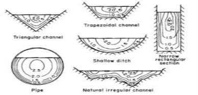
Fig.1: Velocity distribution diagram
Velocity is less near the river banks as there is resistance from the bank.
Dq = discharge through elemental area
Dq = VdA
Total discharge flowing through section
ʃA dQ = ʃA VdA
Also, Q = AV
Average Velocity = Q/A
= VdA/A = Vmax or Vm
Velocity variation with Depth
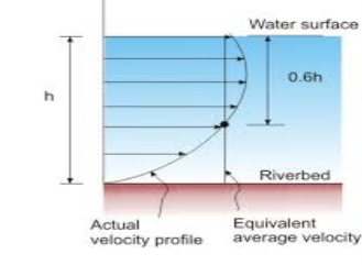
Fig.2: Velcoity Variation with depth
Vavg = V0.2 + V0.8 / 2
Vavg = V0.6
It means maximum velocity at a depth of 0.5y to 0.25y.
Velocity Coefficients
Energy and momentum of flow are calculated in terms og average velocity.
When variation of velocity across the section is high, we need to apply some correction to the computed value of energy and momentum.
This correction factor is called energy efficient or α and momentum coefficient or β.
Pressure distribution in liquid
Hydrostatic pressure distribution-
a) Let’s consider parallel flow on horizontal surface
P = ρgy
Pressure Head = ρgy / ρg = y
b) Parallel flow on sloping ground
Mass = ρ X dA X d
Weight of fluid = ρg d dA
Force acting in downward direction = ρgd cosϴ
Pressure = ρgd cosϴ dA/ dA = ρgd cosϴ
As we know that ϴ is very small nearly equal to 1.
Such as d=y
So, Pressure = ρgy cosϴ
As we know that ϴ is very small
Hydrostatic pressure, Pr = ρgy
c) Curvilinear flow.
Hydrostatic pressure = y
Fluid is subjected in one direction acceleration.
When it is moving in a curvilinear way apart from pressure force. The acceleration is called the centrifugal acceleration.
Centrifugal acceleration = V2/ r
Where, r = radius of curvature
Force = mass X acceleration (due to curvilinear)
Force = ρ d Ay X V2/r-----------for extra additional force
When flow is convex, then the force acts in inward direction & when flow is concave then force will be in outward direction.
Pressure = Force / Area = ρ y V2/r
Pressure head = ρ y V2/r / ρg = yV2/gr
Total Head = y (1 + V2/gr)
Energy efficient ‘α’
Kinetic energy = 1/2mv2
M= mass
V = Velocity

 Velocity coefficient of compound section


 A = A1 + A2 + A3
 Vm = A1V1 + A2V2 + A3V3 / A1 + A2 + A3
α = 1/A ʃA V3/ Vm3 X dA
Fig.3: Compound section
α = 1/ (A1 + A2 + A3) X (A1V13 + A2V23 + A3V33) / (A1V1 + A2V2 + A3V3 / + A1 + A2 A3)3
α = (A1V13 + A2V23 + A3V33) / (A1V1 + A2V2 + A3V3)3 X (A1 + A2 A3)2
Value of velocity coefficient
Types of Channel | α | Β |
Regular Channel | 1.1 – 1.2 | 1.03 – 1.07 |
Natural Channel | 1.15 – 1.5 | 1.05 – 1.17 |
River under ice cover | 1.2 – 2.0 | 1.07 – 1.33 |
River valley over flooded | 1.5 – 2.0 | 1.17 – 1.3 |
Always remember, α > β > 1
Key Takeaways
- Energy Coefficient: It is defined as energy transfer per unit second per elementary area.
- Momentum Coefficient: It is defined as the Momentum transfer per second through an elementary area.
Mass flux
It is defined as transfer of mass per unit time through a unit area.
m = ρx1xv
Energy flux
It is defined as transfer of energy per unit time through a unit area.
E = ½ x mass x v2
= ½ x ρv x v2 x dA
If area = dA, energy transfer per second through an elementary area.
E = 1/2 x ρ3 x dA
Energy through the entire section / unit time
Eactual = ʃA ½ x ρ x v3 dA----------------------Equation 1
Energy computed on the basis of mean velocity
Emean = ½ ρ x Vm3 x A-------------------------Equation 2
α = Equation 1/Equation 2
= ʃA ½ x ρ x v3 dA / ½ ρ x Vm3 x A
= 1/A ʃ V3/ Vm3 X dA
Eactual = Emean X α
Also, M = AV
So, E = ½ X mass X V2
E = ½ X A Vm X Vm2 = ½ A Vm 3
Corrected Energy, Eactual = α X ½ X A Vm3
Momentum coefficient ‘β’
Momentum = mass X velocity = MV
It is defined as the Momentum transfer per second through an elementary area dA.
Momentum = ρ v dA V
= ρ v2 dA
Momentum through the entire section
Mactual = ʃA ρ v2 dA---------------------------------Equation 1
Mmean velocity = ρ A Vm X Vm = ρ A Vm2 ---------------Equation 2
Correction factor ‘β’ = Mactual / Mmean velocity
= ʃA ρ v2 dA / ρ A Vm2
Consider constant density, fluid is incompressible then
β = 1/A ʃV2/Vm2 X dA
Mactual = β X ρ A Vm2
Flow in open channel is governed by gravitational force and Froude’s number
F= V (g D) 1/2
Depending upon Froude’s number, channel is categorized as:
- When F<1 or V< (g D) 1/2, the floor is called subcritical or tranquil or streaming. Depth of flow is greater than critical depth (h).
- When F=1; the flow is said to be in critical state. At this flow, specific energy is minimum.
- When F>1, the flow is said to be supercritical or rapid or shooting or torrential. Depth of flow in channel is less than the critical depth (hc).
It is the depth of flow of water at which the specific energy is minimum. In above figure, point C refers to minimum specific energy. The depth of flow of water at C is called critical depth.
DE / dh = 0
E = h + q2 / 2gh2
d/dh (h + q2 / 2gh2) = 0 or, 1 + q2/2g (-2/h3) = c
q2 / 2g = Constant
1 - q2 / gh3 or, 1 = q2 / gh3
h3 = q2/ g
When specific energy is minimum, depth is critical and I noted by hc.
Or, h = (q2/ g)1/3
Key Takeaway
Critical depth: Depth of flow of water at which the specific energy is minimum.
1.7.1 Specific Energy
The total energy of a flowing liquid per unit weight is given by
Total energy = Z+h+V2/2g
Where,
Z= height of bottom of channel above datum.
h = depth of liquid
V= mean velocity of flow
If channel bottom is taken as datum, Z = 0, then total energy per unit weight of liquid is given by
E = h + V2/2g-----------------Equation 1
The energy given by equation 1 is called specific energy.
Specific energy: Specific energy is the energy per unit weight of the liquid with respect to the bottom of the channel.
Specific energy curve: - It is a curve which shows the variation of specific energy with the depth of flow.
E= h+V2/2g = Ep + Ek------------------Equation 2
Where,
Ep = potential energy
Ek = kinetic energy = v2/2g
Ep = h
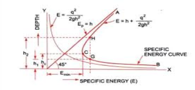
Fig.5: specific energy curve
Consider a rectangular channel in which a study but non-uniform flow is taking place.
Let, Q = discharge through channel
q = discharge per unit width
b = width of channel
h = depth of flow
Then,
q = Q / width= Q / b = Constant
Velocity of flow = V = discharge / area
= Q / b X h= q / h
Substituting value of V equation 2
E= h + q2 / 2gh2 = Ep + Ek
Minimum specific energy in terms of critical depth
E= h + q2/2gh2
When specific energy is minimum, depth of flow is critical. Hence,
Emin = hc + q2/2ghc2------------------Equation 1
Also, hc = (q2/g) 1/3
Substituting this in equation 2
Emin = hc + hc3 / 2hc2
Emin = 3 hc / 2
Hence,
Emin = 3 hc / 2
1.7.2 Specific Force
Consider a channel of large slope and apply momentum principle to the water (Newton's second law states that change in momentum per unit time in a given direction is equal to resultant of all external forces acting on the body in the same direction).
Momentum of flow entering section 1 per sec
= ¥ Q /g X V1
Where,
¥ = Specific weight of flowing fluid
Momentum per second leaving section 2
= ¥ Q /g X V2
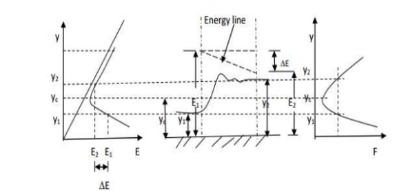
Fig. 6: Specific energy and specific force curve
The forces acting on the body in closed between section 1 and 2 hours:
- P1 & P2 (hydrostatic force at section 1 and 2)
- Wsinϴ (component of weight of water enclosed).
- Ff fictional force
After applying momentum principle, we get
¥ Q (V2 – V1) / g = P1 – P2 = wsinϴ - Ff
Equation becomes
¥ Q (V2 – V1) / g = P1 – P2
Assuming hydrostatic distribution at section 1 and 2:-
P1 = ¥ A1Z1
P2 = ¥ A2Z2
Where,
A1 and A2 are X-SECTION Z1 and Z2 are vertical depth of centroid of the area below surface of flow.
Also
V1 = Q1/A1
V2 = Q2/A2
So, equation becomes
= ¥ Q2 /g (A1 – A2)/ A1A2 = ¥Z1 A1 - ¥Z2 A2
Q2/gA1 + A1Z1 = Q2/gA2 + A2Z2
Sides are equal & represented by F
Hence,
Specific Force = F = Q2/gA + AZ
F1 = F2
Where,
Q2/gA is momentum of flow / unit time / specific weight.
AZ is the Hydrostatic force / specific weight of liquid.
Condition for minimum specific force
Consider F w.r.t ‘y’
Hence, dF / dY = 0
DF / dY = Q2/gA2 X dA/dY + d(AZ) / dy = 0
Also, d (AZ) = (A (Z + dy) + Tdy X dy/2) - AZ
T = dA/dY
Neglecting, small term Tdy2/2, we get
D (AZ) = Ady
Now, dF/dY = -Q2/gA2 X dA/dY + Ady/dy = 0
Or,
Q2T/gA3 = 1
Key Takeaways
Specific force: It is non-gravitational force per unit mass.
Specific energy: Specific energy is the energy per unit weight of the liquid with respect to the bottom of the channel.
1.8.1 Chezy's Equation for Uniform Flow in Open Channel
Velocity is constant, hence there is no acceleration in uniform flow. Using momentum equation to control volume at section 1 and 2. Distance L is apart.
P1 + wsinϴ - Ff – P2 = M2 – M1
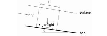
Fig.12: Average shear stress diagram
As flow is uniform
Ff = shear force at boundary
P1 = P2 & M1 = M2
W = YAL, Ff = ZoPL
Zo = average shear stress on weighted parameter P and Y is unit weight of water.
Applying uniform flow condition, equation 1 reduces to
Wsinϴ= Ff
Sinϴ = So
Also,
Zo = average shear stress = K ρ V2
K ρ V2 = ¥RSo -------------------- K= coefficient which depends on the nature of surface and flow parameters.
V = C (RSo) 1/2
Where C = (¥ X 1/ ρK) ½ ------------------ C= coefficient which depends on the nature of surface and flow
Also, Q = AV
Q = AC (RS) ½
For pipe flow, Darcy Weisbach equation is
hf = flv2 / 2gD
hf = head loss due to friction in pipes
f= friction factor
An open channel can be considered into two section
For circular section ----- R= A\P =. π D4/ 2gD = D\4
D= 4R
hf = flv2 / 2gD = flv2 / 2g X 4R
Rearranging gives
V = (8g/f) ½ (R) ½ (hf/L) ½ -------------------- so So = hf /L = Sf = Slope of energy line.
But in uniform flow Sf = So
So, equation is same
V = C (R So) ½ ------------------where C = (8g/f) ½
1.8.2 Manning's Equation for Uniform Flow in Open Channel
Robert Manning
V = 1/n R2/3 S1/2
Where,
n= roughness coefficient known as Manning’s 'n'
R= hydraulic radius
So = bottom slope
Comparison between Manning’s and Chezy's formula
Equating both sides, we get
1/n R2/3 S1/2 = C (R So) ½
C = 1/n R1/6
Also, C = (8g/f) ½ --------------------------- f = Darcy Weisbach friction factor
(8g/f) ½ = 1/n R1/6
f = (n2/ R1/3) 8g
This is the value of Manning ‘n’ for different material.
Factors affecting 'n'
a) Surface roughness
b) Vegetation
c) Cross section irregularity
d) Irregular alignment of channel
e) Sediment load and obstructions
Velocity is retarded near solid boundaries. The surface tension of the liquid-air interface produces resistance to flow and causes maximum velocity to occur at same distance below free surface. Wind also affects the flow and modifies velocity profile.
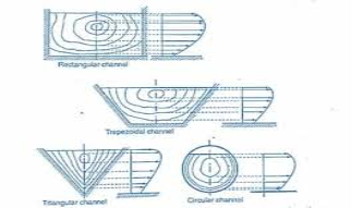
Fig.13: Velocity distribution in OCF
● Velocity distribution depends on various factors like shape of section, roughness of the channel and presence of bends in the channel.
● In straight reach of channel, maximum velocity occurs below the free surface at a distance of 0.15 of depth of flow.
● Velocity at 0.6 depth from free surface is very close to the mean velocity of flow. Also, better approximation can be made by taking average velocity measured at 0.2 depth and 0.8 depth from free surface.
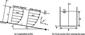
Fig.14: Velocity profile
Also called most economical section or best section. The channel is said to be most efficient channel if it is having minimum wetted perimeter for a given area of flow & also provides maximum discharge and conveyance.
Semicircular shape has least amount of wetted perimeter for a given area.
Rectangular section
Area of flow = A= By = B = A/Y
Wetted perimeter = P = B+2y
P = A/y+2y
For efficient channel section, P should be minimum
DP / dy = 0
DP / dy = d/dy (A/y + 2y) = 0
-A/y3 + 2 = 0 -------- A = 2yc3
Also, Bye = 2ye3 ---------------- ye = Be / 2
Be = 2
Re = Ae / Pe = 2ye2 / B + 2ye
= 2 ye2 / 2ye + 2ye
Re = ye / 2
Suffix 'e' denotes the geometric elements of a hydraulically efficient section.
Key Takeaways
- Most efficient section: A section which having the minimum wetted perimeter for a given area of flow.
- Wetted perimeter: It is the perimeter of the cross-sectional area that is wet.
Compound channel is a channel section composed of main deep portion and one or two plains that carries high water flows. Eg. Rivers.
The flow velocity in the flood plain is lower than in the main channel due to relative smaller water depth and higher bed roughness.
Conveyance of channel:
It expresses the discharge capacity of the channel per unit longitudinal slope. According to Manning's equation,
Q = 1/n AR2/3So1/2
Q = K (So) 1/2--------------------where K = 1/n AR2/3
Where, K is called the conveyance of channel.
For a given channel, AR2/3 is function of depth. According to Chezy's
Q = AC (RSo) 1/2
Q = K (So) 1/2
Equating
AC (RSo) 1/2 = K (So) 1/2
Hence
K = AC (R) ½--------------------conveyance of channel
Channels of first kind:
Channels having top width constant or increasing with depth are called channels of first kind.
AR2/3 = Qn / (So) 1/2
If n, so you are fixed then channel have unique death which is called normal death. E.g. Rectangular trapezoidal etc.
Channels of second kind:
Channels with a closing top width are called channels of second kind. Eg. Circular and triangular.
The variation of AR2/3 with depth is no single valued function of depth. They have two values of depth for a given value of AR2/3.
Second hydraulic exponent 'N':
The conveyance of channel is a function of depth of flow. For gradually varied flow.
K2 = C2 YN
C2 = coefficient
N = exponent called second hydraulic exponent.
To determine N for any channel, a plot of log K versus log Y is prepared. If N is constant between two points (K1, Y1) and (K2, Y2) it is determined by
N = 2 log (K1/K2) / log (Y1/Y2)
Fundamental physical principles
Following are the basic principles.
- Conservation of mass represents continuity equation.
- Conservation of momentum represents Newton's second law of motions.
i.e., F= ma
c. Conservation of energy.
These three conservation laws describe the interaction between a system and surrounding.
Conservation of mass (continuity equation):-
For study flows, the value of discharge Q at various actions must be same.
Q= VA = V1 A1 = V2 A2
V= mean velocity
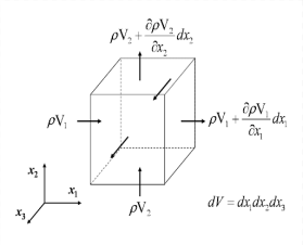
Fig.4: Mass distribution
Conservation of momentum:-
F= rate of change of momentum
F = mv1 – mv2 / t
F = m (v1 – v2 / t) = ma
Conservation of energy:-
When floor is moving from upstream to downstream then energy level AT upstream will be more than energy level at downstream. Energy is conserved from upstream to downstream but some energy is lost due to turbulence or other effects.
Geometric parameter of a channel:-
- Depth of flow (y or h):- It is the vertical distance of the lowest point of channel section from the free surface.
- Top width (T):- It is the width of channel section at the free surface.
- Wetted perimeter (P):- It is the length of channel boundary in contact with flowing water at any section.
- Hydraulic radius for Hydraulic mean depth (R):- It is the ratio of the wetted area to its wetted perimeter.
R= A/P
5. Hydraulic depth (D):- It is the ratio of wetted area to top width.
D= A/T
6. Wetted area (A):- It is the cross sectional area of the flow normal to the direction of flow.
7. Section factor (Z):- It is the product of method area and square root of hydraulic depth.
Z= A (D) 1/2= A x (A/T) 1/2 = (A3/T) ½
Types of channels:-
- Prismatic and non-prismatic channels:-
A channel in cross-sectional shape and size and also the bottom slope are constant is called prismatic channel. Like man made channels (rectangular, circular, trapezoidal etc.)
2. Rigid and mobile boundary channels:-
And rigid channels, the boundary is not deformable, the shape and the roughness are not functions of flow parameters Eg. Sewer, lined canal. No erosion takes place in such channels.
All online channels where boundary undergoes deformation due to continuous process of erosion are called mobile boundary channels.
3. Natural and artificial channels:-
Natural channels have an irregular sections of varying shape developed in a natural way. Eg rivers, lakes.
Artificial channels are those which are billed artificially for carrying water eg channels, rectangular etc.
Critical velocity (Vc):-
The velocity of flow at critical depth is known as critical velocity.
Hc = (q2/ g)1/3
Taking cube to both side we get:-
Hc3 = q2 / g
Ghc3 = q2 ----------------------Equation 1
q = discharge per unit weight = Q/b
= Area XV/b = b X h X v / b = h X v = hc x Vc
Substituting in equation 1:
Ghc = ( hc X Vc )3 = ghc = Vc2
Vc = (ghc) 1/3
Applications of specific energy:-
Most important applications is for analysis of flow through channel transition, flow over raised channel floor-broad crested Weir, through sluice gate opening sector etc.
Two important transition are there:-
- Vertical contraction or channel width with a hump (raised bed of channel at certain location).
- Horizontal contraction or width contraction.
Vertical contraction or channel with the hump:-
We will discuss two conditions:-
a) Subcritical flow:-
Suppose horizontal frictionless rectangular channel of width B & carrying discharge Q at depth y1.
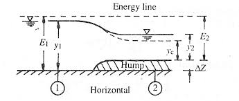
Fig.7: Vertical contraction
Flow is subcritical and at section 2 to a smooth hump of height delta Z is built. There is no loss of energy between 1 and 2 and also hump causes of specific energy at 1 and 2 and also come causes specific energy at section 2 to decrease by ▲Z.
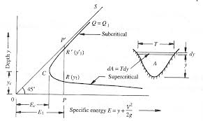
Fig.8: Energy diagram
Specific energy at section 1-------E1 = Y1 + V2/2g
Specific energy at section 2-------E2 = E1 - ▲Z
Also,
E2 = Y2 + V2/2g
As ▲Z increases, y2 decreases at point C the value of hump height will be maximum (▲Zm), Here
Y2= Yc & E2 = Ec
E2 = E1 -▲Zm or Ec = Yc + Q2/2gB2yc2
If ▲Z > ▲ Zm then flow is not possible even with given specific energy.
When O < ▲z > ▲Zm upstream water level will be constant at, when y1 while y2 decreases ▲Z and goes on increasing till YC at ▲Zm.
When ▲Z> ▲Zm, y1 will change to y1 and y2 will continue to remain Yc.
1.10.2 Minimum size of hump for critical flow:-
When ▲Z = ▲Zm, the critical flow occurs at section 2 but as ▲Z > ▲Zm the specific energy at section 1 will be changing,
Thus ▲Zm is called minimum size of ham for critical flow to occur.
At ▲Z = ▲Zm, E2 = Ec = 3/2yc
E1 = Ec + ▲Zm
▲Zm = E1 - 3/2yc
▲Zm / y1 = E1 / Y1 – 3Yc / 2Y1
E1 / Y1 = 1 + f12/2 & Yc = (q2/g) 1/3---------put in equation
▲Zm / y1 = (1 + f12/2 – 3/2 (q2/g) 1/3 X 1/Y1)
▲Zm / y1 = (1 + f12/2 – 3/2 f1 2/3)
When there is energy loss due to hump:-
Let h1 be energy loss
E1 = E2 + ▲Z + HL
Then,
▲Zm / y1 + hL/Y1 = (1 + f12/2 – 3/2 f1 3/2 X f/2)
Supercritical flow condition:-
If y1 is in supercritical flow condition then depth of flow will increase due to reduction in specific energy.
At Yc
▲Z = ▲Zm
Or
▲Z > ▲Zm
The death over hump y2=YC will remain constant and upstream
Depth y1 will change. It will degrees to have higher specific energy.
Horizontal contraction or width contraction:-
Consider a frictionless horizontal channel of width B1 carrying discharge Q at depth Y1. At section 2 in the channel width is constricted to B2 by smooth transition. There is no energy loss, the specific energy at section 1 is equal to specific energy at section 2.
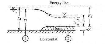
Fig.9: Contraction diagram
E1 = Y1 + V12/2g = Y1 + Q2/2gB12Y12
E2 = Y2 + V22/2g = Y2 + Q2/2gB22Y22
At Section 1 -------q1 = Q/B1
At Section 2 -------q2 = Q/B2
Since B2 < B1 so, q2 > q1
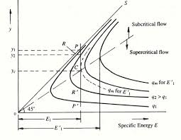
Fig.10: Specific energy diagram
In Specific energy diagram,
P on the curve q1 corresponds to death Y1 & specific energy E1.
At section 2, E1 = E1 and q = q2, here the point P will move vertically downward to point R on the curve to reach depth Y2.
If B2 is smaller, q2 will increase, and Y2 will decrease.
When B2 is contracted till its last limit B2 = B2 min, then discharge intensity is maximum, q2 = q2 max; critical flow conditions pre valid.
At B2 = B2 min,
Y2 = critical depth at section 2
E1 = Emin = Yc + Q2/2g (B2 min) 2 Yc2
For rectangular channel at critical depth:-
Yc = 2/3 Ec
But as E1 = Ec
Y = Yc = 2/3 Ec = 2/3 E1
Yc = (Q2/ (B2 min) 2)1/3 or B2 min = (Q2/gYc) 1/2
B2 min = (27 Q2/ 8g E13) ½ Put Yc = 2/3 E1
If B2 < B2 min, the discharge intensity will be larger than qmax.
Now, the death will have to increase to Y1 so that
E1’ = Y1’ + Q2/2g B12Y12 --------is formed which will be sufficient to cause critical flow section 2.
Now critical depth is given by
Yc 2 = (Q2/ B22g) 1/3 = (q22/g) 1/3
Ec 2 = Yc 2 + Vc 22/2g = 1.5
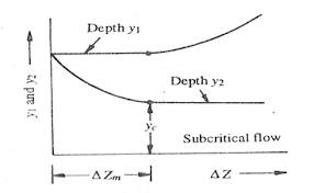
Fig.11: Energy depth diagram
As B2 < B2 min, Yc2 will be larger than Yc also,
E1' = Ec2 = 1.5 Yc2
Depth at section 2 is not constant but increases as Y1' and hence E1' rises.
UNIFORM FLOW:-
Flow in a channel is said to be uniform, if its properties remains constant with respect to space.
DY / ▲L = 0
DV / ▲L = 0 ------------Uniform flow is possible only in prismatic channel.
Equivalent roughness:-
In some channels, different parts have different roughness coefficient, forces channels equivalent roughness coefficient is determined which is also called composite roughness.
Calculated using Horton method
Consider a channel having its parameter composed set of M type of roughness.
P1, P2, Pm are length of these parts.
n1, n2, n3… nm are roughness coefficient.
Let to each part Pi be associated with partial area Ai, so that
Summation of Ai = A1 + A2 + ------+ Am = A = Total area
Mean velocity in each area is V
V1 = V2 = Vm = V
By Manning's formula
So1/2 = V1n1/R12/3 = V2n2/R22/3-----= Vmnm/Rm2/3
= VXn/R2/3 ----------------------- n = equivalent roughness
(Ai/A) 2/3 = ni Pi2/3 / n P2/3
Ai = A (ni) 3/2 Pi / n3/2 P
n = (£ni3/2 Pi) 2/3 / P2/3
References:
- Chow, V.T. “Open Channel hydraulics” McGraw Hill Publication
- Subramanya, K., Flow through Open Channels, TMH, New Delhi
- Ranga Raju, K.G., Flow through open channels, T.M.H. New Delhi
- Rajesh Srivastava, Flow through Open Channels, Oxford University Press
- Streeter, V.L.& White E.B.,” Fluid Mechanics” McGraw Hill Publication
- Modi & Seth “Hydraulics & Fluid Mechanics” Standard Publications.
- RK Bansal “Fluid Mechanics and Hydraulic Machines” Laxmi Publication
- AK Jain “Fluid Mechanics” Khanna Publication.
- Houghtalen, “Fundamentals of Hydraulics Engineering Systems” 4/e Pearson Education, Noida