Unit 3
Rapidly varied flow
It is a non-uniform open channel where the fluid depth changes rapidly over a small reach of the channel.
Hydraulic jump
Hydraulic jump occurs supercritical (high velocity and small depth) flow subcritical (low velocity and large depth) flow causing a jump in the flow depth.
Examples
a) When bed slope of a channel changes from steep to mild, the supercritical depth on the steep channel jumps to the subcritical depth on the mild channel.
b) Downstream of a sluice gate, the supercritical flow under the gate meets the uniform flow depth (subcritical) in the downstream channel.
c) At the toe of spillway, where high velocity flow over the spillway meets a larger flow depth downstream.
Application of hydraulic jump
The formation of jump involves air entertainment, mixing and energy loss, which leads to various practical benefits such as
a) Dissipation of energy of water falling over a Weir or spillway.
b) Through mixing of a chemical (E.g. a purifying agent) in water by introducing it upstream of the jump.
c) Improvement of water quality by increasing the dissolved oxygen content through air entrainment.
d) Reducing the uplift pressure on an apron on the channel led by forming a jump on or before the apron thereby increasing the flow depth on the apron.
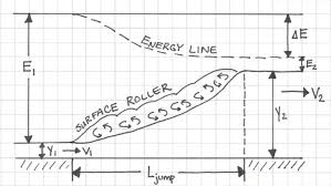
Fig.1: Hydraulic Jump
Section 1 and 2 who is length of jump and Y1 and Y2 are initial and final death after jump of subcritical stream. Two depths Y1 and Y2 at the end of the jump are called sequent depth. Due to high turbulence and shear action of the roller, there is loss of energy in the jump between section 1 and 2.
Momentum equation for the jump
Consider the channel inclined at an angle of 
Section 1 and 2 indicate the beginning and end of the jump. The channel is assumed to be prismatic channel of arbitrary shape.
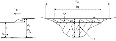
Fig.2: Momentum Equation for the jump
Following assumptions are made in analysis of a hydraulic jump:
- Loss of head due to friction at the walls and channel bed is negligible.
- The pressure distribution is hydrostatic.
- The channel is horizontal or it has small slope. The weight component in direction of flow is neglected.
- The momentum correction factor is unity.
A control volume enclosing the jump is indicated by dashed line. The flow is considered to be steady.
Applying momentum equation to the control volume:
P1 = Pressure force at section 1= 
 is the depth of centroid of the area below water surface.
P2 = Pressure force at section 1= 
Fs = shear force on the control surface
Wsin = longitudinal component of weight of water contained in the
Control volume
M2 = momentum flux going out through control surface = 
M1 = momentum flux going in through control surface = 
For small  cos
cos = unity
Wsin is neglected.
For horizontal channel  Wsin
Wsin = 0
= 0
Key Takeaways
- Open channel: - Open-channel flow, a branch of hydraulics and fluid mechanics, is a type of liquid flow within a conduit or in channel with a free surface, known as a channel.
- Spillway: - A spillway is a structure used to provide the controlled release of flows from a dam or levee into a downstream area, typically the riverbed of the dammed river itself.
3.2.1 Evaluation of the Jump Elements in Rectangular Channels on Horizontal Bed
Consider a horizontal frictionless rectangular channel. Assuming channel width to be unity, the momentum equation can be written as:
 , Fs = 0,
  =
= 
 =
=  , B =1
 -
-  =
=  -------------------------------1
Taking  =
=  = 1 &
= 1 & 
Applying continuity equation
A1V1 = A2V2
V1Y1 = V1Y1 = q (discharge intensity)
 (
( =
=  )------------------------------2
 =
=  (
( -----------------3
Y1Y2 (Y1 + Y2) =  = 2
= 2 --------------------------4
Since for rectangular channel  =
=  or
or  =
=  1/3
1/3
 1+
1+  =
= 
F1 = Froude no =  (Supercritical Froude No.)
 =
=  (-1 +
(-1 + ) ------------------------------------5
Above equation gives ratio of sequent depth and related to Froude number. This is called Belanger momentum equation.
 1+
1+  =
= 
F2 = Froude no =  (Subcritical Froude No.)
Solving for  yields.
 =
=  (-1 +
(-1 + )
)
EL = E1 - E2 E1 & E2 are specific energy at section 1and section 2.
EL = (Y1+ ) - (Y2+
 )
)
= (Y1-Y2) + 
Substituting value of 
EL = (Y1 + Y2) +  (
(
On solving,
EL = 
EL = 
The relative energy loss

 -------------------------------------6
Also,  = 1+
= 1+  ----------------------------------7
Putting in equation 6
EL =  ------------8
Put value of  from equation 5 to 8
 =
= 
Length of jump:
Lj = 6.9 (Y2 – Y1)
Expression for energy loss in non-rectangular channel:
EL = E1 – E2 = Y1 – Y2 +  (
( -
- 
Classification of jumps
- Hydraulic jump in horizontal rectangular channel are classified into five categories based on Froude’s number F1 of the supercritical flow
- Undular jump: - In this type of jump water surface is having a small ripple. The sequent depth ratio is very small and ratio
 is practically zero.
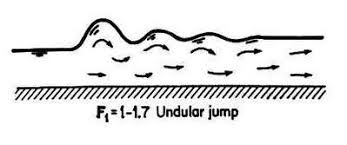
Fig.4: Undular jump
2. Weak jump: The surface roller gradually increases from F1= 1.7 to the end F1 = 2.5. The energy dissipation is very small about 5% it at F1 equal to 1.7 and 18% at F1 = 2.5%.
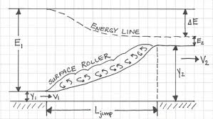
Fig.5: Weal jump
3. Oscillating jump: This jump has high velocity flow of water which oscillates in a random manner between the bed and the surface. The energy dissipation is moderate about 45% at F1 = 4.5.
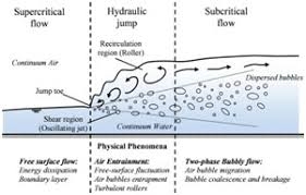
Fig.6: Oscillating jump
4. Steady jump: Here the jump is well established, the roller and the jumper action are fully developed and the energy dissipation ranges from 45 % to 70%.

Fig.7: Steady jump
5. Strong or choppy jump: - Here the water surface is very rough and choppy. The sequent depth ratio is large and energy dissipation is highly pronounced greater than 70%.
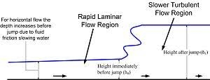
Fig.8: Strong or choppy jump
B. Classification on the basis of location of jump
- Jump at Vena contracta: - When Y1 equal to Y2, a hydraulic jump will form at vena contracta called free jump at vena contracta.
- Free repelled jump: - When Y1 is less than Y2 the jump is repelled downstream of Vena contracta. The death Y1 will be larger than vena contractor then Ya. It is called triple jump with sequent depth less than and equal to Y2 called free jump.
- Submerged or drowned jump: - If still water is greater than Y2 then supercritical stream is summarized and resulting jump is called submerged or drowned jump.
Key Takeaways
- Vena contracta: It is the point in a fluid stream where the diameter of the stream is the least, and fluid velocity is at its maximum, such as in the case of a stream issuing out of a nozzle (orifice).
- Hydraulic jump: When liquid at high velocity discharges into a zone of lower velocity, a rather abrupt rise occurs in the liquid surface.
It is rapidly varied unsteady flow with occurs change in the discharge or depth or both.
Surge that produces increases in depth is called positive surge and one that causes decrease in depth is called negative search.
It can travel in upstream or downstream direction.
Depending upon movement, it can be classified into four types.
a) Positive surge moving downstream.
b) Positive surge moving upstream.
c) Negative surge moving downstream.
d) Negative surge moving up stream.
Positive surges are stable in nature and negative surges are unstable in nature and their form changes with advantages of surge.
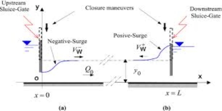
Fig.9: Positive and Negative Surge
Positive surge moving downstream
Consider sluice gate play rest and causes positive surge moving downstream. The absolute velocity Vw is assumed to be constant; the unsteady state is converted to study state by applying relative velocity concept.
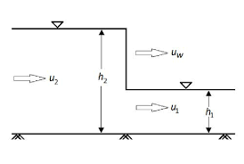
Fig.10: Positive surge moving downstream
Continuity equation to control volume:
A2 (Vw – V2) = A1 (Vw – V1) ----------------------1
Momentum equation to 1 & 2
P1 – P2 = M2 – M1
 =
=  =
=  -
- 
(As  = 1)
= 1)
 -
-  =
=  (Vw – V1)
  ---------------2
From equation 1
V2 =  V1 + (1 +
  Vw
Vw
Substituting this in equation 2, we get
 2 = g
2 = g 
 (
( )
)
Vw = V1 + 
As surge is moving downstream,  is positive.
For rectangular channel with unit width, the continuity equation is :
Y1  = Y2
= Y2 
Momentum equation is:
 -
-  =
=  1 (Vw – V1)
From equation
V2 =  V1 + (1-
  ) Vw
) Vw
Substituting value of V2
 =
= 
 (
(
Positive surge moving upstream
Consider sluice gate is suddenly closed to cause positive surge to move upstream. Section 1 and 2 refers to condition before and after passage of surge.
Unsteady flow converted to steady flow. Consider unit weight of horizontal frictionless rectangular channel.
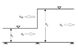
Fig.11: Positive charge moving upstream
Applying continuity equation:
Y1  = Y2 (Vw + V2) -----------------------1
Applying momentum equation:
 -
-  =
=  (Vw + V1)
 -
-  =
=  (Vw + V1) (V2 – V1)
From equation 1:
V2 =  V1 – (1-
  ) Vw
) Vw
Substituting value of V2 in equation 1
 =
= 
 (
(
Positive surges moving downstream and upstream are called as moving hydraulic jump.
Negative surge
In negative surge, a point on top of surge moves faster than point on lower water surface. This results in scratching of the wave profile. The shape of negative surge varies with time due to stretching activity by varying values Vw along its height. The negative surge is composed of a series of elementary negative wave off of celerity  superimposed on existing flow.
Consider an elementary negative wave of height  y. The motion is converted to an equivalent steady state flow buy superimposition of -Vw on the system.
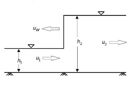
Fig.12: Negative Surge
Applying continuity equation:
(Vw - V2)Y2 = (Vw – V1) Y1
Let, Y1 = V1, Y1 = Y, V2 = V – , Y2 = Y -
On simplifying
 y = (Vw – V)
 =
= 
Applying momentum equation to control volume
 =
=  (Vw – V1) Y1
On solving,
 =
=  : C = Celerity of negative wave
Also, (Vw – V) 2 = C2 = gY : C = 

(Vw – V) = 

So,  =
=  =
= 

 =
= 

As,  = 0
= 0
 =
= 
 -------- This is basic differential equation for negative wave.
Negative surge / wave moving downstream
Consider negative surge moving downstream in a wide rectangular channel due to partial closure of sluice gate.
 =
= 
On integration, V = 2 + constant
Apply Boundary condition:
At, V = V1, Y = Y1
V1 = 2 + Constant
Constant = V1 - 2
V = V1 + 2 - 2
- 2
Wave travels downstream.
C = Vw – V = 
Vw = V + 
Putting value of V
Vw = V1 + 3 - 2
- 2 ------------------------1
If surge Vw moves x distance in time‘t’
X = Vwt
X = (V1 + 3 - 2
- 2 )t -------------------2
The above equation represents profit of negative wave I terms of x, y and t.
From equation 1 & 2 we get,
X =  t
t
V = 
Negative surge moving upstream
Consider negative wave produced by instantaneously raising a sluice gate located at downstream and off the channel.
 =
= 
On integrating, V = -2  + Constant
Apply boundary condition:
At V = V1, Y = Y1
V1 = - 2 + Constant
Constant = V1 + 2
V = V1 - 2 + 2
+ 2
As negative wave moves upstream:
C = Vw + V = 
Vw = - V
- V
Now,
Vw =  - 2
- 2 1
1
Let’s consider surge is moving with velocity Vw moves x distance in time‘t’.
X = -Vwt
Putting values,
(-X) = Vwt = (3 - 2
- 2 – V1) t
Key Takeaways
- Positive surge moving downstream: The wave in the form of a sharp or sudden increase in the flow-depth travels faster downstream relative to the initial flow velocity prior to the opening of the gate
- Positive surge moving upstream: The wave in the form of a sharp or sudden increase in the flow-depth travels faster upstream against the initial flow velocity directed downstream.
- Negative surge moving downstream: A negative surge is an unsteady open channel flow motion characterized by a decrease with time of the flow depth.
- Negative surge moving up stream: A negative surge is an unsteady open channel flow motion characterized by a decrease with time.
The velocity of surge relative to the initial velocity of surge in channel is known as the celerity of surge.
For surge moving downstream = Cs = Vw – V1
For surge moving upstream = Cs = Vw + V1
Cs =  + Y2)
+ Y2)
If, Y2 = Y1
Cs = 
Key Takeaway
Celerity: The flood wave which generates during the positive or negative surges is called the celerity.
Wind waves that propagate along the interface between water and air are called surface gravity wave.
As wind blows, pressure and wind forces disturb the equilibrium of water surface. These forces transfer energy from air to water, forming waves.
3.6.1 Deep Water Wave
Here, d
Where, d – Water depth
Y - Wavelength
Particles near the surface moves in circular path, making wind wave combination of longitudinal and transverse wave motion.
3.6.2 Shallow Water Wave
Here, d
Particles near the surface are compressed and move in the form of ellipse.
At deep water, the orbital motion of fluid particles decreases rapidly with increasing depth below the surface.
At shallow water wave, movement is elliptical.
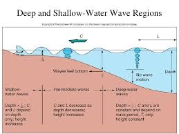
Fig.13: Deep and shallow water waves
Consider a sinusoidal wave: -
A = amplitude T = Time period
 =
=  = Frequency K =
  = Wave number
Phase speed of surface wave is approximated by
C = 
In shallow water wave: - d << Y
C =  (Phase speed independent of wavelength)
Cg =  = C (Group sped same as phase speed)
In deep water wave: - d > 
C =  =
=  (Longer wave moves faster)
Cg = 
 =
=  C (Group speed is half phase speed)
Key Takeaways
Surface gravity wave: The type of wave motion which most people are familiar with are waves that occur on the free surface of water.
3.2.4 Jumps in horizontal non rectangular channel
Computer horizontal frictionless channel any arbitrary shape. For hydraulic jump in channel momentum equation is applicable.
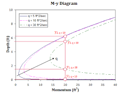
Fig.3: Jumps in horizontal non rectangular channel
Assuming  = 0 &
= 0 &  1 =
1 =  2 = 1
2 = 1
P1 = P2 = M2 = M1
 -
-  =
=  -
- 
 -
-  =
=  -
- 
Rearranging,
P1 + M1 = P2 + M2
In general, P + M =  (A
(A = Constant
 = Ps = A
 = Constant
Ps =  ----- is specific force
3.2.5 Sequent depth ratio: -
P + M =  (A
(A = Constant
Applying at section 2
 + A1
+ A1 =
=  + A2
+ A2
A2 - A1
- A1 =
=  (
( -
- 
A1 (
( - 1) =
  (
( -
-  -------1
F12 =  Putting this is equation 1
( - 1) =
  (
( ) (1 -
  )
)
Key Takeaways: -
- Sequent depth ratio: - Conjugate, or sequent, depths are the paired depths that result upstream and downstream of a hydraulic jump, with the upstream flow being supercritical and downstream flow being subcritical.
- Froude no: - The inertial force divided by gravitational force is defined as Froude’s number.
References:
- Chow, V.T. “Open Channel hydraulics” McGraw Hill Publication
- Subramanya, K., Flow through Open Channels, TMH, New Delhi
- Ranga Raju, K.G., Flow through open channels, T.M.H. New Delhi
- Rajesh Srivastava, Flow through Open Channels, Oxford University Press
- Streeter, V.L.& White E.B.,” Fluid Mechanics” McGraw Hill Publication
- Modi & Seth “Hydraulics & Fluid Mechanics” Standard Publications.
- RK Bansal “Fluid Mechanics and Hydraulic Machines” Laxmi Publication
- AK Jain “Fluid Mechanics” Khanna Publication.
- Houghtalen, “Fundamentals of Hydraulics Engineering Systems” 4/e Pearson Education, Noida