UNIT 4
Impulse Momentum
Based on the law of conservation of momentum which states that the net force acting on a fluid mass is equal to the change in momentum of flow per unit time in that direction.
F = ma a – acceleration in same direction
a = 
F = m =
=  m is constant
F =  -------- momentum principle
Also, Fdt = d (mv) ------------ Impulse momentum equation
Impulse momentum equation states that the Impulse of a force f acting on a fluid mass m in a short interval of time ‘dt’ is equal to the change of momentum d(mv) in the direction of the force.
Key Takeaways
Impulse: It quantifies the overall effect of the force acting over time.
Liquid coming out in form of jet from outlet of a nozzle, which is fitted to a pipe through which the liquid is flowing under pressure. If same fixed on moving plate is placed in path of jet a force is exerted by the jet on the plate which is obtained by impulse momentum equation.
4.2.1 Force exerted by the jet on a stationary plate
a) When the plate is vertical to the jet:
v = Velocity of jet, d = diameter of jet
a = Cross-sectional area of the jet = 
Jet will move along the plate after striking it. Plate is at right angle to jet so that will be deflected by 90 after striking.
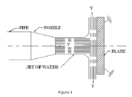
Fig.1: The plate is vertical to the jet
Hence velocity components will be zero.
Force exerted by jet on the plate in the direction of jet.
Fx = rate of change of momentum in the direction of force.
= 
= 
= 
= 
= 
Fx = 
b) When the plate is inclined
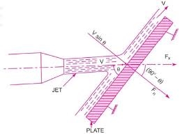
Fig. 2: The plate is inclined
v = Velocity of jet in the direction of x
 = Angle between jet and plate
a = Area of cross section of the jet
Then, mass of water per second is striking the plate = 
If plate is smooth and assume that there is no loss of energy due to impact of jet, jet will move over the plate after striking with velocity equal to the initial velocity.
Force exerted by jet on the plate in the direction normal to the plate ‘Fn’.
Fn = mass of jet striking/sec X (initial velocity of jet before striking in n
Direction – final velocity after striking in n direction)
=  =
= 
This can be resolved into two components, Fx & Fy.
Fx = Component of Fn in the direction of flow
Fx = Fn Cos (90 = Fn Sin
 =
=  Sin
Sin
Fx =  Sin2
Sin2
Fy = Fn Sin (90 = Fn Cos
Fy =  Sin
Sin Cos
Cos
c) The plate is stationary and curved
- Jet strikes curved plate at the centre
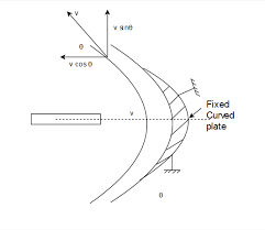
Fig.3: jet strikes curved plate at the centre
Component of velocity in the direction of jet = -V Cos (-V as direction is opposite)
Component of velocity perpendicular to the jet = v sin
Force exerted by jet in the direction of jet Fx1 = mass /sec (V1x – V2x)
V1x Initial velocity in the direction of jet = V
V2x = Final velocity in the direction of jet = - V Cos
Fx = 
 =
= 

Fx =  2 (1+
2 (1+ )
)
Fy = mass/sec x (V1y – V2y)
V1y = Initial velocity in the direction of y = 0
V2y = Final velocity in the direction of y = 
Fy = 
Fy =  2
2 
Angle of deflection of jet = (180
Ii. Jet strikes the curved plate at one end tangentially when the plate is symmetrical
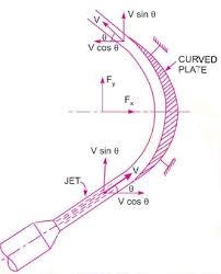
Fig.4: jet strikes the curved plate
Let jet strike the curved fixed plate at one end tangentially. Let curved plate be symmetrical about x-axis.
The angle made by two tangents at two ends of the plate will be same.
V = Velocity of jet
 = angle made by jet with x-axis at inlet tip of plate
Plate is smooth.
Force exerted by jet of water in x & y directions.
Fx = mass/sec X (V1x – V2x)
Fx = 

Fx =  2
2 
Fy =  (V1y – V2y)
Fy = 
 = 0
= 0
4.2.2 Force exerted by jet on moving plates
a) Flat vertical plate moving in the direction of jet and away from jet
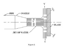
Fig.5: Flat vertical plate moving in the direction of jet and away from jet
Vertical plate is moving with the uniform velocity away from the jet.
V = Velocity of jet
u = Velocity of flat plate
a = Area of cross section of jet
Jet strikes the plate with not the absolute velocity ‘V’ but with the relative velocity (V-u).
Relative velocity of jet with respect to plate = (V-u)
Mass of water striking the plate per second =  =
= 
Force exerted by jet on moving plate in the direction of jet.
Fx = mass of water striking/sec X (initial velocity – final velocity)
Fx = 

Fx =  (V-u) 2
Work done per second by jet on the plate = 
= Fx X u
Work done per second by jet on the plate =  (V-u) 2 X u
b) Force on incline plate moving in the direction of jet
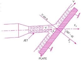
Fig.6: Force on incline plate moving in the direction of jet
 = Angle between jet and plate
Relative velocity of jet of water = (V-u)
The velocity with which jet strikes = (V-u)
Mass of water striking per second =  (V-u)
(V-u)
Assume smooth plate and loss of energy due to impact of plate is zero.
Force exerted by jet of water on the plate in the direction normal to the plate:-
Fn = mass striking/sec X (initial velocity in normal direction with which jet
Get strikes – final velocity)
Fn =  (V-u)
(V-u) 
Fn =  (V-u) 2 Sin
This force is resolved into two components Fx & Fy in the direction of the jet and perpendicular to the jet respectively.
Fx = Fn Sin =
=  (V-u) 2 Sin
Fy = Fn Cos =
=  (V-u) 2 Sin
 Cos
Cos
Work done per second by the jet on the plate
= Fx X distance per second in the direction of x.
= Fx X u =  (V-u) 2 Sin
 X u
X u
=  (V-u) 2 Sin2
 X u N-m/sec
c) Force on curved plate when plate is moving in the direction of jet
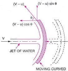
Fig.7: Force on curved plate when plate is moving in the direction of jet
Component of velocity in the direction of jet = - (V-u) Cos
Component of velocity in the direction of jet = - (V-u) Sin
Mass of water striking the plate =  X (velocity with which jet strikes plate
=  (V-u)
(V-u)
Force exerted by jet of water on curved plate in the direction of jet: -
Fx = mass striking/sec X (initial velocity – final velocity)
=  (V-u)
(V-u) 
=  (V-u)
(V-u)
=  (V-u) 2 (1+
Work done by jet on the plate per second
= Fx X distance travelled per second in direction of x
= Fx X u
Work done by jet on the plate per second =  (V-u) 2 (1+
 X u
X u
Key Takeaways
Impact: The force exerted by the surface on the jet is then obtained by applying Newton's Second Law, i.e. the force normal to the surface is equal to the rate of change of momentum, or change of momentum per second, normal to the surface.
It is a device used to move fluids, such as liquids, gases etc. It is a device that provides energy to the fluid pressure energy or kinetic energy or both of the fluid by converting the mechanical energy.
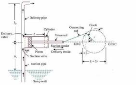
Fig.8: Reciprocating pump
Classification of pumps
Based on the transfer of mechanical energy, the pumps are classified as: -
- Rotodynamic pumps
a) Radial flow pumps
b) Axial flow pumps
c) Mixed flow pumps
2. Positive displacement pumps
a) Gear pump
b) Progressing cavity pump
c) Roots type pump
d) Reciprocating pump
4.3.1 Reciprocating Pumps
A reciprocating pump is a positive displacement one which works on the principle of a reversing piston motion within a cylinder drawing in liquid during forward stroke, and delivering it under pressure during return or backward stroke.
- Reciprocating pump generally operates at low speeds and it is coupled to an electric motor with V-belts.
- The reciprocating pump is best suited for relatively small flow rate and high heads. In oil drilling operation this type of pump is very common.
Main components of the reciprocating pump
- Cylinder with a piston, piston rod, connecting rod, cranks.
- Suction pipe.
- Delivery pipe.
- Suction, delivery valve.
Classification of reciprocation pump
On the basis of water being in contact with one side or both sides of the piston.
a) Single acting cylinder.
b) Double acting cylinder.
If the water is in contact with one side of the piston, the pump is called single acting pump and if the water is in contact with both sides of the piston, the pump is called double acting pump.
Classification of reciprocation pump
According to the number of cylinders provided-
- Single cylinder pump.
- Double cylinder pump.
- Multi cylinder pump.
Single cylinder pump: A reciprocating pump having only one cylinder is known as single cylinder pump. It may be either single action or double action pump.
Double (Two) cylinder pump: Pumps having more than one cylinder are known as multi cylinder pumps. Two pumps, three pumps, three throw pumps etc. having two or three single acting cylinders driven from cranks set at 180° , as shown in Fig a. Or 120°, their main advantage is more uniform discharge as compared with a single cylinder pump.
Work done by reciprocating pump
Single acting pump:- In the single acting pump, as explained earlier, it has only one suction stroke and one delivery stroke for one revolution of the crank. It delivers the liquid only during the delivery stroke. Hence, the flow rate of the liquid delivered per second.
Q =  ------------------1
L = length of stroke = 2r
r = radius of stroke
A = Cross-section of cylinder
N = revolutions of crank per minute
The theoretical work done by the pump = Wnet =  (Hs + Hd) ------------------------2
Hs = suction head
Hd = delivery head
Wnet = 
Double acting pump: It has two suction and two delivery pipes connected to one cylinder.
Power required to drive the pump = 
Two-throw pump: In two-throw pump there are two cylinders with one suction and one delivery pipe. The rate of flow the through two throw pumps is
Q =  m3/sec
Three-throw pump: It has three cylinders and three pistons working with three connecting rods fitted with one suction pipe and delivery pipe. The rate of flow through three-throw pump is
Q =  m3/sec
Slip of reciprocating pump
Slip of pump is defined as the difference between the theoretical discharge (Qth) and actual discharge Qact.
Slip = Qth - Qact
Negative Slip: In most of the cases, the slip is positive. But in some cases, the actual discharge of the pump may be more than the theoretical discharge in which case Cd will be more than one and the slip will be negative, which is known as negative slip. This occurs in pumps having long suction pipe and low delivery head, especially when these are running at high speed. This is due to the reason that the inertia pressure in the suction pipe becomes so large that it causes the delivery valve to open before the suction stroke is completed. Thus, some liquid is pushed directly into the delivery pipe even before the delivery stroke is commenced. This results in making the actual discharge more than the theoretical discharge.
Key Takeaways
- Slip: Slip is the loss of pumping capacity due to fluid leaking back through a pump from the discharge side to the inlet side.
- Pump: A pump is a device that moves fluids (liquids or gases), or sometimes slurries, by mechanical action, typically converted from electrical energy into Hydraulic energy.
4.3.2 Centrifugal Pumps
Hydraulic machine that converts the mechanical energy into hydraulic energy / pressure are called pumps. If the mechanical energy is converted into pressure energy by means of centrifugal force acting on the fluid, the hydraulic machine is called centrifugal pump.
It acts as a reverse of an inward radial flow reaction turbine. Flow is in the radial outward direction.
Works on the principle of forced vortex flow, when a certain mass of liquid is rotated by an external torque, the rise in pressure head of the rotating liquid takes place.
Rise in pressure head =  or
or 
At the outlet of the impeller, the rise in pressure head will be more due to which the liquid can be lifted to a higher level.
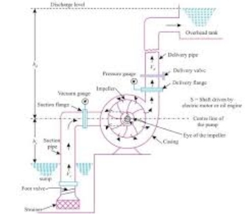
Fig.9: Centrifugal pump
Main parts of a centrifugal pump
- Impeller
It is the rotating part of the impeller. It consists of a series of backward curved vanes. It is mounted on a shaft which is connected to the shaft of an electric motor.
2. Casing
It's an air tight passage surrounding the impeller and is designed in such a way that the kinetic energy of the water discharged at the outlet of the impeller is converted into pressure energy before the water leaves the casing and enters the delivery pipe.
Types of casings
a) Vortex casing.
b) Volute casing.
c) Casing with guide blades
3. Suction pipe with foot valve and strainer
A pipe whose one end dips into water in a sump is known as suction pipe. a foot valve is a non return valve or one-way valve which is fitted at the lower end of suction pipe. It only opens in upward direction. A strainer fitted at the lower end of the suction pipe.
4. Delivery pipe
A pipe whose one end it is connected to the outlet of the pump and other end deliver the water at a required height is known as delivery pipe.
Work done by the centrifugal pump (impeller) on water
Work is done by impeller on water. The water enters the impeller radially at inlet for best efficiency of the pump.
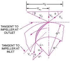
Fig. 10: Work done by the centrifugal pump (impeller) on water
The absolute velocity of water at inlet makes an angle 900 with the direction of motion of the impeller at inlet.
 = 90
= 90 and Vw1 = 0
Let,
N = Speed of impeller in RPM
D1 = Diameter of impeller at inlet
U1 = Tangential velocity of impeller at inlet = 
D2 = Diameter of impeller at outlet
U2 = Tangential velocity of impeller at outlet = 
V1 = Absolute velocity of water at inlet Vr1 = Relative velocity of water at inlet
 Angle made by relative velocity (V1) at inlet with the direction of motion of vane.
 Angle made by relative velocity (Vr1) at inlet with the direction of motion of vain.
V2,  Corresponding values at outlet
When water enters,  = 90
= 90 and Vw1 = 0
Centrifugal pump is reverse of radically inward flow turbine.
The work done by water on a runner per second per unit weight of the water is striking per second is given by (for turbine).
=  Vw1 U1 - Vw2 U2)
Work done by impeller on water per second =  Vw2 U2
W = weight of water = 
Q = AV = 
Q =  Q = Volume of water
B1 & B2 are width of impeller at inlet & outlet
Definition of heads and efficiencies of a centrifugal pump
- Suction head (hs)
It is the vertical height of the centerline of the centrifugal pump above the water surface in the tank from which water is to be lifted. This is also called suction lift and is denoted by h.
2. Delivery head (hd)
The vertical between the centre line of the pump and the water surface in the tank to which water is delivered is known as delivery head.
3. Static head (Hs)
The sum of suction head and delivery head is known as static head.
Hs = hs + hd
4. Manometric head (Hm)
It is the head against which a centrifugal pump has to work.
Hm = Head imparted by the impeller – Loss of head in the pump to the water
=  - Loss of head in the impeller and casing
=  if loss of pump is zero.
Head imported by the impeller- loss of head in the pump to the water
Head in the impeller and casing
If loss of pump is zero
Hm = Total head at the outlet of pump-total head at the inlet of pump
Hm =  -
- 
 = Pressure head at outlet of pump
 = Velocity head at outlet of pump
 = Velocity head in delivery pipe
 Vertical height of the outlet of pump from datum line
Hm = hs + hd + hfs + hfd + 
hfs = Frictional head loss in suction pipe
hfd = Frictional head loss in delivery pipe
Vd = Velocity of water in delivery pipe
5. Efficiencies of centrifugal pump
a) Manometric efficiency: - (nmax)
Ratio of manometric head to the head imparted by the impeller to the water is known as manometric efficiency.
nmax = 
=  =
= 
Power given to water at outlet of the pump = WHm/1000 KW
Power at impeller =  KW
KW
=  KW
KW
nmax =  =
= 
b) Mechanical efficiency: - (nm)
The power at the shaft of the centrifugal pump is more than the power available at the impeller of the pump centrifugal pump is known as mechanical efficiency.
nm = 
The power at the impeller = 
= 
nm =  / S.P : S.P = Shaft power
c) Overall efficiency: - (no)
Ratio of power output of the power to the power input to the pump. The power output of the pump in KW.
=  =
= 
Power input to the pump = Power supplied by the electric motor
Power input to the pump = Shaft Power of the pump
no = 
no = nmax X nm
Key Takeaways
- Vortex: Vortex pumps (also called recessed impeller pumps) are based on the principle of creating a vortex flow with a recessed impeller that is positioned away from the path of the liquid.
- Volute: The volute casing is designed to guide the flow out of the impeller in order to convert the fluid flow's kinetic energy into static pressure; it serves to collect the fluid discharged from the impeller and route it to the discharge nozzle (also see Pump casing).
Cavitations are a common problem for centrifugal pumps. If you hear strange noises coming from your pump there’s a good chance cavitation is the issue.
Cavitations are the formation and accumulation of bubbles around a pump impeller. This tends to form in liquids of any viscosity as they are being transported through and around a pump system. When each of these tiny bubbles collapses or bursts, it creates a high energy shock wave inside the liquid. Imagine throwing a stone into a pond. The circular ripples which are created in this process are similar to cavitation bubbles exploding. The difference here is that due to the sheer number of bubbles creating these shock waves, the impeller and other pump components can be eroded over time.
Types of Cavitation
There are five different types of cavitation. It is important to understand these for when we look at ways to prevent cavitation from happening.
- Vaporization: Also known as inadequate NPSHa cavitation or ‘classic cavitation’, this is the most common form. It occurs when a centrifugal pump imparts velocity on a liquid as it passes through the eye of the impeller.
2. Turbulence: If parts of the system - pipes, valves, filters, elbows etc. - are inadequate for the amount or type of liquid you are pumping, this can create vortexes in said liquid. In essence, this leads to the liquid becoming turbulent and experiencing pressure differences throughout. These differences can erode solid materials over time, in the same way that a river erodes the ground.
3. Vane Syndrome: Also known as ‘vane passing syndrome’, this type of cavitation occurs when either the impeller used has too large a diameter, or the housing has too thick a coating. Either or both of these creates less space within the housing itself.
4. Internal Re-circulation: In this instance, the pump cannot discharge at the proper rate and so the liquid is re-circulated around the impeller. The liquid travels through low and high pressure zones resulting in heat and high velocity.
5. Air Aspiration Cavitations: Another common form. Air can sometimes be sucked into a pump through failing valves or other weak points such as joint rings. Once inside, the air has nowhere to go but along for the ride.
Symptoms of Cavitation
As with any structural or mechanical issue, it’s important to have a reliable maintenance process. Checking on components and the performance of your pump is a great way to identify early warning signs of cavitation.
One or a combination of the following symptoms can be a result of cavitation:
- Decreased Flow or Pressure: If your pump is not producing the amount of flow as stated by the manufacturer, this could mean that cavitation is occurring.
- Unexpected Vibrations: Cavitations can cause unusual vibrations not accounted for by both the equipment used and the liquid being pumped.
- Impeller Erosion: Pieces of impeller within the system, or eroded parts are a sure fire sign of cavitation.
- Seal/Bearing Failure: Cavitations can also cause the seals to leak or fail.
- Erratic Power Consumption: If bubbles are forming around the impeller, or the impeller itself has already started to fail, you may notice that your pump requires more power than usual to transport its media. You may also notice fluctuations of power use as suction rises and falls depending on how the impeller is performing.
- Noise: If there’s one sign of cavitation, it’s noise. When the bubbles implode they can make a series of bubbling, cracking, sounds. Alternatively, it might sound like tiny marbles or ball bearings rattling around inside the impeller housing.
Key Takeaways
- NPSHa: Net positive suction head.
The net positive suction head available to a centrifugal pump
Combines the effect of atmospheric pressure, water temperature,
Supply elevation and the dynamics of the suction piping.
A centrifugal pump containing two or more impellers is called a multistage centrifugal pump. The impellers may be mounted on the same shaft or on different shafts. If we need higher pressure at the outlet, we can connect impellers in series. If we need a higher flow output we can connect impellers in parallel. All energy added to the fluid comes from the power of the electric or other motor force driving the impeller.
Pump Efficiency
Pump efficiency may be defined as the ratio of power added to the fluid in relation to the power required to drive the pump. Efficiency is never a single fixed value for any given centrifugal pump, it is a function of discharge and therefore also the operating head. The efficiency tends to increase with flow rate up to a point midway through the operating range (peak efficiency) and then declines as flow rates rise further, the resulting curve is almost parabolic in shape. It is important that the system is designed in order that the pump will be operating at or close to its peak efficiency. This is particularly difficult for those systems with time variant flow rates, such difficulties may be overcome through the use of variable frequency drives to adjust the speed of the electric drive motor. Unless carefully designed, installed and monitored, pumps will be, or will become inefficient, wasting a lot of energy. Efficiency will decline over time due to wear of the impeller and hence should be regularly tested to ensure they are operating normally.
Energy usage
He energy usage in a pumping installation is determined by the flow required, the height lifted and the length and friction characteristics of the pipeline. The power required to drive a pump (Pi), is defined simply using SI units by:
Pi = 
Where:
Pi is the input power required (W)
 is the fluid density (kg/m3)
g is the standard acceleration of gravity (9.80665 m/s2)
H is the energy Head added to the flow (m)
Q is the flow rate (m3 /s)
n is the efficiency of the pump plant as a decimal
The head added by the pump (H) is a sum of the static lift, the head loss due to friction and any losses due to valves or pipe bends all expressed in meters of fluid. Power is more commonly expressed as kilowatts (103 W) or horsepower (multiply kilowatts by 0.746). The value for the pump efficiency may be stated for the pump itself or as a combined efficiency of the pump and motor system.
Key Takeaways
Efficiency: Pump efficiency refers to how effectively a pump can convert one form of energy to another based on the difference between horsepower going into and out of a pump.
The following factors influence the choice of pump for a particular operation:
- The quantity of liquid to be handled: This primarily affects the size of the pump and determines whether it is desirable to use a number of pumps in parallel.
- The head against which the liquid is to be pumped. This will be determined by the difference in pressure, the vertical height of the downstream and upstream reservoirs and by the frictional losses which occur in the delivery line. The suitability of a centrifugal pump and the number of stages required will largely be determined by this factor.
- The nature of the liquid to be pumped. For a given throughput, the viscosity largely determines the frictional losses and hence the power required. The corrosive nature will determine the material of construction both for the pump and the packing. With suspensions, the clearance in the pump must be large compared with the size of the particles.
- The nature of power supply. If the pump is to be driven by an electric motor or internal combustion engine, a high-speed centrifugal or rotary pump will be preferred as it can be coupled directly to the motor.
- If the pump is used only intermittently, corrosion troubles are more likely than with continuous working.
Reciprocating pumps Vs centrifugal pumps
The advantages of reciprocating pumps in general over centrifugal pumps may be summarized as follows:
- They can be designed for higher heads than centrifugal pumps.
- They are not subject to air binding, and the suction may be under a pressure less than atmospheric without necessitating special devices for priming.
- They are more flexible in operation than centrifugal pumps.
- They operate at nearly constant efficiency over a wide range of flow rates.
The advantages of centrifugal pumps over reciprocating pumps are:
- The simplest centrifugal pumps are cheaper than the simplest reciprocating pumps.
- Centrifugal pumps deliver liquid at uniform pressure without shocks or pulsations.
- They can be directly connected to motor derive without the use of gears or belts.
- Valves in the discharge line may be completely closed without injuring them.
- They can handle liquids with large amounts of solids in suspension.
Key Takeaways
Air binding: Operation in an air bound condition for an extended period, over about 10 minutes, can cause overheating and failure of the pump (seizing of the impeller in the casing).
References
1. Chow, V.T. “Open Channel hydraulics” McGraw Hill Publication
2. Subramanya, K., Flow through Open Channels, TMH, New Delhi
3. Ranga Raju, K.G., Flow through open channels, T.M.H. New Delhi
4. Rajesh Srivastava, Flow through Open Channels, Oxford University Press
5. Streeter, V.L.& White E.B.,” Fluid Mechanics” McGraw Hill Publication
6. Modi & Seth “Hydraulics & Fluid Mechanics” Standard Publications.
7. RK Bansal “Fluid Mechanics and Hydraulic Machines” Laxmi Publication
8. AK Jain “Fluid Mechanics” Khanna Publication.
9. Houghtalen, “Fundamentals of Hydraulics Engineering Systems” 4/e Pearson Education, Noida