UNIT 5
Rotodynamic Machines
The important element of a rotodynamic machine, in general, is a rotor consisting of some vanes or blades. There always exists a relative motion between the rotor vanes and the fluid. The fluid has a component of velocity and hence of momentum in a direction tangential to the rotor. While flowing through the rotor, tangential velocity and hence the momentum changes.
In a turbine, the tangential momentum of the fluid is reduced, and therefore work is done by the fluid to the moving rotor. But in the case of pumps and compressors, there is an increase in the tangential momentum of the fluid, and therefore work is absorbed by the fluid from the moving rotor.
5.1.1 Basic Equation of Energy Transfer in Rotodynamic Machines
The basic equation of fluid dynamics relating to energy transfer is the same for all rotodynamic machines and is a simple form of "Newton’s Laws of Motion" applied to a fluid element traversing a rotor. Here we shall make use of the momentum theorem applies to a fluid element while flowing through fixed and moving vanes. Figure 1 represents diagrammatically a rotor of a generalized fluid machine, with 0-0 the axis of rotation and w the angular velocity. Fluid enters the rotor at 1, passes through the rotor by any path, and is discharged at 2. Points 1 and 2 are at radii r1 and r2 from the centre of the rotor, and the directions of fluid velocities at 1 and 2 may be at any arbitrary angles. For the analysis of energy transfer due to fluid flow in this situation, we assume the following:
(a) The flow is steady, that is, the mass flow rate is constant across any section (no storage or depletion of fluid mass in the rotor).
(b) The heat and work interactions between the rotor and its surroundings take place at a constant rate.
(c) Velocity is uniform over any area normal to the flow. This means that the velocity vector at any point is representative of the total flow over a finite area. This condition also implies that there is no leakage loss and the entire fluid is undergoing the same process.
The velocity at any point may be resolved into three mutually perpendicular components as shown in Fig 1. The axial component of velocity Va is directed parallel to the axis of rotation, the radial component Vf is directed radically through the axis to the rotation, while the tangential component Vw is directed at right angles to the radial direction and along the tangent to the rotor at that part.
The change in the magnitude of the axial velocity components through the rotor causes a change in the axial momentum. This change gives rise to an axial force, which must be taken by a thrust bearing to the stationary rotor casing. The change in the magnitude of radial velocity causes a change in momentum in the radial direction.
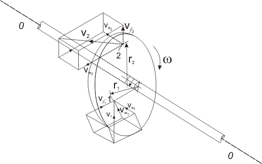
Fig.1: Components of flow velocity in a generalized fluid machine
However, for an axis-symmetric flow, this does not result in any net radial force on the rotor. In the case of a non-uniform flow distribution over the periphery of the rotor in practice, a change in momentum in the radial direction may result in a net radial force that is carried as a journal load. The tangential component only affects the angular motion of the rotor. In consideration of the entire fluid body within the rotor as a control volume, we can write from the moment of momentum theorem
T = m (Vw2r2 - Vw1r1) ----------------------------------1
Where T is the torque exerted by the rotor on the moving fluid, m is the mass flow rate of fluid through the rotor. The subscripts 1 and 2 denote values at inlet and outlet of the rotor respectively. The rate of energy transfer to the fluid is then given by
E = Tw = m (Vw2r2w- Vw1r1w) = m (Vw2U2 - Vw1U1) -----------2
Where w is the angular velocity of the rotor and U= wr which represents the linear velocity of the rotor. Therefore U2 and U1 are the linear velocities of the rotor at points 2 (outlet) and 1 (inlet) respectively. Equation 2 is known as Euler's equation about fluid machines. Equation 2 can be written in terms of head gained 'H' by the fluid as
H =  ------------------------------3
In usual convention relating to fluid machines, the head delivered by the fluid to the rotor is considered to be positive and vice-versa. Therefore, equation 3 written with a change in the sign of the right-hand side in accordance with the sign convention as
H =  ---------------------------------4
Key Takeaways:
- Steady Flow: - A flow in which the velocity of the fluid at a particular fixed point does not change with time is called also steady flow.
- Non Uniform Flow: - Flow is said to be non-uniform, when there is a change in velocity of the flow at different points in a flowing fluid, for a given time.
The Pelton wheel turbine is a tangential flow impulse turbine used for high heads of water and it is invented by Lester Allan Pelton, an American Engineer.
The energy available at the inlet of the turbine is only kinetic. The pressure energy at the inlet and outlet of the turbine is atmospheric.
This is a hydraulic turbine and the main uses of these turbines are in the hydropower plant to generate electricity.
Hydroelectricity is the most widely used form of renewable energy. It is a flexible source of electricity and also the cost of electricity generation is relatively low.
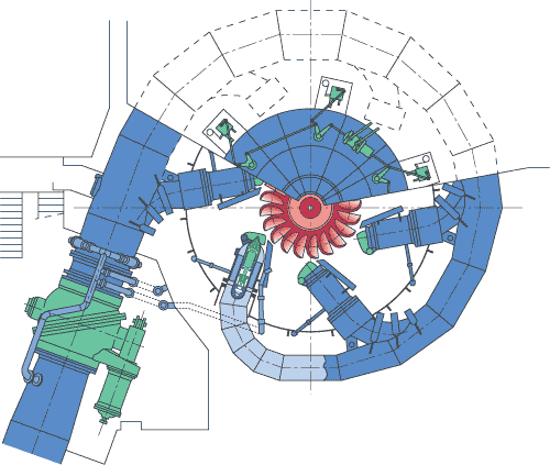
Fig.2: Pelton Wheel
5.2.1 A Pelton wheel turbine consists of four-major parts and those are:
Nozzle: -The amount of water striking the buckets of the runner is controlled by providing a spear in the nozzle.
The speed is a conical needle which is operated either by a hand wheel or automatically in an axial direction depending upon the size of the unit.
When the spear is pushed forward into the nozzle and the amount of water striking the runner is reduced. On the other hand, if the sphere is pushed back, the amount of water striking the runner increases.
Runner and buckets: -The runner or blade consists of a circular disc on the Periphery of which several buckets evenly spaced are fixed. The Shape of the bucket is of a double hemispherical cup or bowl. Each bucket is divided into two symmetrical parts by a dividing wall which is known as a splitter.
Casing: - The function of the casing is to prevent the splashing of the water and to discharge water to the tailrace. It also acts as a safe ground against accidents. It is made of cast iron or fabricated steel plates. The casing of the Pelton wheel does not perform any hydraulic function.
Breaking jet: - When the nozzle is completely closed by moving the spear in the forward direction, the amount of water striking the runner reduces to zero. But the runner due to inertia goes on revolving for a long time. To stop the runner in a short time, a small nozzle is provided which directs the jet of water on the back of the vanes. This jet of water is called a breaking jet.
5.2.2 Working Principle of Pelton Wheel Turbine
Let's understand the figure or layout of the hydropower plant. The water is stored at the high head. From there it comes through the penstock and reaches the nozzle of the Pelton turbine. The nozzle increases the kinetic energy of the water and directs the water in the form of a jet.
Now, the jet of water from the nozzle strikes the buckets (vanes) of the runner. So that the runner rotates at very high speed and the quantity of water striking the vanes or buckets is controlled by the spear present inside the nozzle and then the main important process is the generator is attached to the shaft of the runner which converts the mechanical energy (rotational energy) of the runner into electrical energy.
Key Takeaways:
- Hydroelectricity: - Hydroelectricity is electricity made by generators that are pushed by the movement of water. It is usually made with dams that block a river to make a reservoir or collect water that is pumped there.
A jet of water from the nozzle strikes the buckets of the splitter, which splits up the jet into two parts. These parts of the jet glide over the inner surfaces and come out at the outer edge. Work done from the jet of water to the buckets is determined by applying the momentum equation.
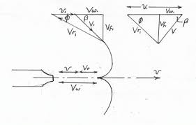
Fig.3: Velocity triangle of Pelton Turbine
The splitter is the inlet tip and the outer edge of the bucket is the outlet tip of the bucket.
Let, H = Net head acing on the Pelton Wheel
= Hg – Hf
Where, Hg = Gross Head and Hf = 
Where D* = Diameter of the penstock
D = Diameter of the wheel
N = Speed of the wheel in r.p.m
d = Diameter of the jet
Then, V1 = Velocity of the jet at inlet =  ------------------------1
U = u1= u2 = 
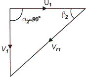
The velocity triangle at the inlet will be a straight line where
Vr1 = V1 – u1 = V1 – u
Vw1 = V1
 And
And 
From the velocity triangle at the outlet, we have
Vr1 = Vr2 and Vw2 = Vr2  - u2
- u2
The force exerted by the jet of water in the direction of motion is given by
Fx =  (Vw1 + Vw2)
As the angle  is an acute angle, the positive sign should be taken
a = Area of jet = 
Now work done by the jet on the runner per second
Fx X u =  (Vw1 + Vw2) X u N-m/s -------------------------2
The power is given to the runner by the jet
=  kW -----------------------3
Work was done/second per unit weight of water striking/second.
= 
=  =
=  -------------------4
The energy supplied to the jet at the inlet is in the form of kinetic energy and is equal to  .
.
The kinetic energy of jet per second =  X V12
X V12
Key Takeaways:
- Kinetic energy: - The impulse turbine is the type where the head of the supply water is converted into kinetic energy before it is directed through a nozzle as a high-velocity jet onto the vanes or buckets that are mounted on the periphery of the turbine's wheel.
5.4.1 Hydraulic Efficiency:
It is the ratio of power generated by the runner of the turbine to the water-energy supplied to the bucket of the runner.
nh = 
The expression is also written as:
nh = 
Here H is a Net head developed by the water at the inlet, and it can find out by this equation:
H = Hg – Hf
Hf = 
5.4.2 Mechanical Efficiency:
It is defined as the power available at the shaft to the power produced by the runner
nm = 
nm = 
5.4.3 Volumetric Efficiency:
It is a ratio of the actual quantity of writing on the runner blades per second to the net quantity of water supplied by the jet to the turbine per second is known as volumetric efficiency.
nv = 
nv = 
5.4.4 Overall Efficiency:
It is defined as a ratio of the power available at the shaft to the net power available at the base of the nozzle.
no = 
no = 
Key Takeaways:
- Efficiency: - Turbine efficiency is the ratio of actual work output of the turbine to the net input energy supplied in the form of fuel.
The amount of water striking the buckets (vanes) of the runner is controlled by providing a spear in the nozzle. The spear is a conical needle that is separated either by a hand wheel or automatically in an axial direction depending upon the size of the unit. When the spear is pushed forward into the nozzle the amount of water striking the runner is reduced. On the other hand, if the spear is pushed back, the amount of water striking the runner increases.

Fig.4: Spear Valve
Key Takeaways:
- Vanes: - Guide Vanes are fixed grooves found in turbines that help direct water, gas, or air around bends at maximum efficiency. As Impellers increase or decrease the flow of a substance through a system, Guide Vanes ensure that the substance is passed evenly and as smoothly as possible.
In a reaction turbine, a part of the head (H) acting on the turbine is converted into kinetic energy and the rest remains as a pressure head. The water first enters a set of movable blades (guide vanes) and passes over a set of fixed runner blades. There exists a difference of pressure between these two sets of blades which is called ‘reaction pressure’ and is responsible for the motion of the runner blades.
Degree of reaction: it is defined as the ratio of the static pressure drop to the total pressure drop in the stage.
R = 
By the application of Bernoulli’s equation to the inlet and outlet section of the runner blade,
 = Wnet -
  ---------------------1
Where, P1 & P2 = Pressure at the inlet
V1 & V2 = Absolute of velocity at inlet and outlet section
Wnet = Work done by the turbine runner
 = Wnet and this represents a pure reaction turbine. The intermediate type of turbine is described by the degree of reaction.
R =  ---------------------------2
R =  ------------------------------3
Wnet = Vu1u1/g
R =  ---------------------4
5.6.1 Types of reaction turbine
Mainly two types of reaction turbine: (i) Outward radial flow reaction turbine (ii) Inward flow reaction turbine.
(i) Outward radial flow reaction turbine: - Outwards radial flow reaction turbine in which water from casing enters the stationary guide wheel. The guide wheel consists of guide vanes with direct water to enter the runner which is around the stationary guide wheel. The water flows through the vanes of the runner in the outward radial direction and is discharged at the outer diameter of the runner. The inner diameter of the runner is the inlet and the outer diameter is the outlet. The velocity triangle at the inlet and outlet will be drawn by the same procedure as adopted for the inward flow turbine. The work is done by the water on the runner per second, power output developed and hydraulic efficiency will be obtained from the velocity triangle. In this case, as an inlet of the runner is at the inner diameter of the runner, the tangential velocity at the inlet will be less than of at outlet.\
(ii) Inward flow reaction turbine: - Inward radial flow reaction turbine in which water from casing enters the ‘Guide Vanes Section’ through the guide vanes water flows to the runner in the inward radial direction and discharge at the inner diameter of the runner. The inner diameter of the runner is the outlet and the diameter of the runner is the inlet.
Key Takeaways:
- Static pressure: - In the design and operation of aircraft, static pressure is the air pressure in the aircraft's static pressure system. In fluid dynamics, many authors use the term static pressure in preference to just pressure to avoid ambiguity.
- Total Pressure: - Total pressure is the measure of the total energy of the airstream and is equal to static pressure plus velocity pressure.
5.7.1 Francis Turbine
The inward flow reaction turbine having radial discharge at the outlet is known as Francis Turbine, after the name of J.B> Francis, an American engineer who is the beginning designed inward radial flow reaction type of turbine. In the modern Francis turbine, the water enters the runner of the turbine in the radial direction at the outlet and leaves in the axial direction at the inlet of the runners. Thus the modern Francis turbine is a mixed flow type turbine.
The velocity triangle at the inlet and outlet of the Francis turbine is drawn in the same way as in the case of the inward flow reaction turbine. As in the case of Francis turbine, the discharge is radial at the outlet, the velocity at whirl at the outlet (i.e., Vw2) will be zero. Hence the work done by water on the runner per second will be
= 
And work done per second per unit weight of water striking per second = 
Hydraulic efficiency will be given by. nh = 
5.7.1.1 Components parts:
Penstock: - It is a large-sized conduit that conveys water from the upstream of the dam to the turbine runner. A trash rack is provided at the inlet of the penstock to obstruct the entry of debris and other foreign matter.
Scroll Casing: - The water from the penstock is conducted through the scroll casing and distributed around the stay ring and the complete circumference of the guide vane cascade. The decrease in area is in proportion to the decreasing volume of water to be handled and that ensures the velocity of water is constant along its path. The scroll casings are normally welded steel plate construction for a turbine at low, medium as well as high heads. The stay vanes are given a favorable hydraulic shape to conduct the water towards the guide vanes with minimum losses. The stay vanes also carry the axial forces inside the scroll casing. The scroll casing is provided with taps for pressure measurements, drain, air vent outlets, and a manhole.
Guide Vanes: - A series of airfoil-shaped vanes, called the guide vanes or wicket gates, are arranged inside the casing to form some flow passages between the casing and the runner blades. The vanes are shaped according to the hydraulic design specification and given a smooth surface finish. The bearings of the guide vane shafts are lubricated with oil or grease. The guide vanes direct the water onto the runner at an angle appropriate to the design. It provides the degree of adaptability to the quantity of water to be admitted to the runner in the wake of load variations
Runner and Runner Blades: - Runner is a rotor that has passages formed between crown and shroud in one direction and two consecutive blades on the other. These passages take water in at the outer periphery in the radially inward direction and discharge it in a direction parallel to the axis of the rotor. The driving force on the runner is both due to impulse and reaction effects. It may either be of cast steel or a welded construction where hot pressed plate blades are welded to the cast hub and ring. In most cases, the runner is made of stainless steel. The water flow through the labyrinth seals is a leakage flow and is not utilized by the runner. On high head turbines, the leakage water is normally utilized as cooling water for the generator, transformers, and bearings.
- Draft Tube: - The draft tube forms the water conduit from the runner to the draft outlet. It consists of the draft tube cone and the draft tube steel plate lining. It consists of the draft tube cone and the draft tube steel plate lining. The aim of the draft tube is also to convert the main part of the kinetic energy at the runner outlet to pressure energy at the draft tube outlet. This is achieved by increasing the cross-section area of the draft tube in the flow direction. In an intermediate part of the bend, however, the draft tube cross-sections are decreased instead of increased in the flow direction to prevent separation and loss of efficiency. The draft tube cone is a welded steel plate design and consists normally of two parts, the upper and lower cone. The inlet part of the upper cone is made of stainless steel. It is normally provided with two manholes for inspection of the runner from below. The lower part is designed as a dismantling piece and is mounted to a flange on the draft tube bend top. This design is always used for units where the runner is dismantled downwards. For units being dismantled upwards, the draft tube cone is made in one piece. The draft tube lining is completely embedded in concrete.
5.7.1.2 Important relation for Francis turbine
The following are the important relations for Francis turbines:
- The ratio of the width of the wheel to its diameter is given as
n = 
The value of n varies from 0.10 to 0.40.
2. The flow ratio is given as,
Flow ratio =  and varies from 0.15 to 0.30.
3. The speed ratio =  and varies from 0.6 to 0.9.
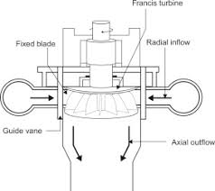
Fig.5: Francis turbine
5.7.2 Kaplan Turbine
5.7.2.1 Introduction A higher specific speed corresponds to a lower head. This requires that the runner should admit a comparatively large quantity of water. For a runner of a given diameter, the maximum flow rate is achieved when the flow is parallel to the axis. Such a machine is known as an axial flow reaction turbine. An Australian engineer, Vikton Kaplan first designed such a machine. The machines in this family are called Kaplan Turbines.
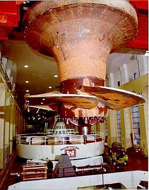
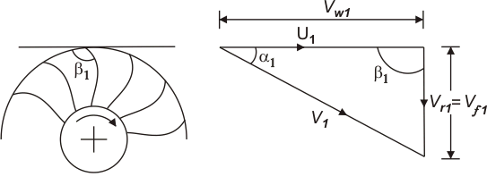
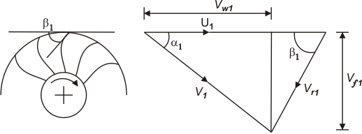
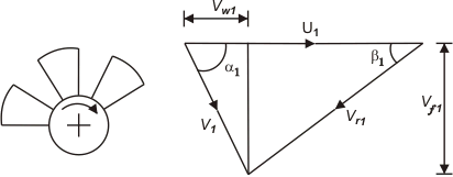
Development of Kaplan Runner from the Change in the Shape of Francis Runner with Specific Speed The Francis runner (radial flow runner) at low, normal, and high specific speeds. As the specific speed increases, the discharge becomes more and more axial. The fourth type is a mixed flow runner (radial flow at inlet axial flow at the outlet) and is known as Dubs runner which is mainly suited for high specific speeds. This type of runner is the most suitable one for very high specific speeds and is known as Kaplan runner or axial flow runner. From the inlet velocity triangle for each of the five runners, as shown in Figs, it is found that an increase in specific speed (or a decrease in the head) is accompanied by a reduction in inlet velocity V1. But the flow velocity Vf1 at inlet increases allowing a large amount of fluid to enter the turbine. The most important point to be noted in this context is that the flow at the inlet to all the runners, except the Kaplan one, is in radial and tangential directions. Therefore, the inlet velocity triangles of those turbines in a plane containing the radial and tangential directions, and hence the flow velocity Vf1 represents the radial component of velocity. In the case of a Kaplan runner, the flow at the inlet is in axial and tangential directions. Therefore, the inlet velocity triangle in this case in a place containing the axial and tangential directions, and hence the flow velocity Vf1 represents the axial component of velocity Va. The tangential component of velocity is almost nil at the outlet of all runners. Therefore, the outlet velocity triangle is identical in the shape of all runners. However, the exit velocity V2 is axial in Kaplan and Dubs runner, while it is the radial one in all other runners.
|
The function of the guide vane is the same as in the case of the Francis turbine. Between the guide vanes and the runner, the fluid in a propeller turbine turns through a right-angle into the axial direction and then passes through the runner. The runner usually has four or six blades and closely resembles a ship's propeller. Neglecting the frictional effects, the flow approaching the runner blades can be considered to be a free vortex with whirl velocity being inversely proportional to the radius, while on the other hand, the blade velocity is directly proportional to the radius. To take care of this different relationship of the fluid velocity and the blade velocity with the changes in radius, the blades are twisted. The angle with the axis is greater at the tip than at the root.
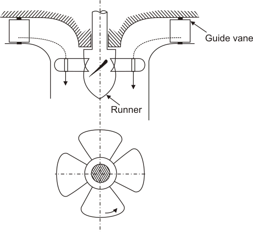 |
Fig.12: A propeller of Kaplan turbine |
Different types of draft tubes incorporated in reaction turbines The draft tube is an integral part of a reaction turbine. Its principle has been explained earlier. The shape of the draft tube plays an important role especially for high specific speed turbines since the efficient recovery of kinetic energy at runner outlet depends mainly on it. Typical draft tubes, employed in practice, are discussed as follows.
- Straight divergent tube: - The shape of this tube is that of the frustum of a cone. It is usually employed for low specific speed, vertical shaft Francis turbine. The cone angle is restricted to 8 0 to avoid the losses due to separation. The tube must discharge sufficiently low under tailwater level. The maximum efficiency of this type of draft tube is 90%. This type of draft tube improves the speed regulation of a falling load.
- Simple elbow type: - The vertical length of the draft tube should be made small to keep down the cost of excavation, particularly in rock. The exit diameter of the draft tube should be as large as possible to recover kinetic energy at the runner's outlet. The cone angle of the tube is again fixed from the consideration of losses due to flow separation. Therefore, the draft tube must be bent to keep its definite length. A simple elbow type draft tube will serve such a purpose. Its efficiency is, however, low (about 60%). This type of draft tube turns the water from the vertical to the horizontal direction with a minimum depth of excavation. Sometimes, the transition from a circular section in the vertical portion to a rectangular section in the horizontal part is incorporated in the design to have a higher efficiency of the draft tube. The horizontal portion of the draft tube is generally inclined upwards to lead the water gradually to the level of the tailrace and to prevent the entry of air from the exit end.
|
Key Takeaways:
- Flow ratio: - The ratio of the two for a well-designed Francis turbine is probably around 1:1. The Francis design has been used with head heights of from 3 to 600 m but it delivers its best performance between 100 and 300 m.
- Speed ratio: - The Tip Speed Ratio (TSR) is an extremely important factor in wind turbine design. TSR refers to the ratio between the wind speed and the speed of the tips of the wind turbine blades. The further away from the center, the faster the blades spin.
- Vortex: - In fluid dynamics, a vortex (plural vortices/vortexes) is a region in a fluid in which the flow revolves around an axis line, which may be straight or curved.
Hg = Gross Head
Hf = Loss of head in penstock
H = Hg - Hf = Net Head
Also,
H = (Total energy available at the exit of penstock) – (Total energy at exit from
Draft tube)
H =  -
- 
If draft tube, tail race level is taken as datum level
H =  -
- 
Where,  = Velocity at the exit of the draft tube
Work was done per second on runner = 
= 
Where, Q = A1V1 (Discharge in m3/second)
Work was done = 
Key Takeaways:
- Gross Head: - Gross head is basically defined as the difference between the head race level and tail race level when water is not flowing.
- Loss of Head: - Loss of Head is the dissipation of energy in any moving fluid because of friction.
5.9.1 Unit speed (Nu)
Speed of the turbine working under the unit head.
u = 
N = 
N = K1 
If H = 1m, then N = Nu
Nu = 
5.9.2 Unit Power (Pu)
Power developed by the turbine working under the unit head.
P = w QH = w AVH
V = 
P = w A H
H
P = w A  H3/2
H3/2
P = K H3/2
If H = 1m, then P = Pu
Pu = K
Pu = 
5.9.3. Unit Discharge (Qu)
The discharge of the turbine working under 1m head.
Q = AV = A 
Q = K 
If H = 1m, then Q = Qu
Qu = K
Therefore, Qu = 
Key Takeaways:
- Speed: - The speed of an object is the magnitude of the change of its position; it is thus a scalar quantity.
- Power: - Power is the amount of energy transferred or converted per unit of time.
- Discharge: - Rate of flow in m3/second.
For predicting the performance of the hydraulic structures (such as dams, spillways, etc.) or hydraulic machines (such as turbines, pumps, etc.) before actually constructing or manufacturing, models of the structures or machines are made and tests are conducted on them to obtain the desired information. Model is a small replica of the actual structure or machine. The actual structure or machine is called a Prototype. Models can be smaller or larger than the Prototype. Model Analysis is actually an experimental method of finding solutions for complex flow problems.
5.10.1 Similitude or Similarities
A similitude is defined as the similarity between the model and prototype in every aspect, which means that the model and prototype have similar properties. Types of Similarities:
• Geometric Similarity → Length, Breadth, Depth, Diameter, Area, Volume, etc.
• Kinematic Similarity → Velocity, Acceleration, etc.
• Dynamic Similarity → Time, Discharge, Force, Pressure Intensity, Torque, Power.
Geometric Similarity: The geometric similarity is said to exist between the model and prototype if the ratio of all corresponding linear dimensions in the model and prototype are equal. Mathematically,
 =
=  =
= , and
, and  = Lr2, and
  Lr3
Lr3
Where Lr= Scale Ratio
Kinematic Similarity: The kinematic similarity is said to exist between model and prototype if the ratios of velocity and acceleration at corresponding points in the model and at the corresponding points in the prototype are the same. Also, the directions of the velocities in the model and prototype should be the same.
 = Vr and
  = ar
= ar
Where Vr = Velocity ratio and ar = area ratio
Dynamic Similarity: The dynamic similarity is said to exist between model and prototype if the ratios of corresponding forces acting at the corresponding points are equal.
 = Fr where Fr is the force ratio
It means for the dynamic similarity between the model and prototype, the dimensionless numbers should be the same for model and prototype.
5.10.2 Specific Speed
The speed of the turbine which is identical in shape, geometrical dimensions, blade angles, gate opening, etc. which would develop unit power when working under the unit head is called a specific speed.
no = 
P = no 
P  HQ -------------------------1
As we know that, u  V
V
V 

u 

But, u =  ----------------------2
u  DN -----------------------3
From equation 2 and 3
 DN
DN
D 

Discharge through turbine
Q = AV
A = BD
A  BD (Since B
 )
)
A  D2
D2
Q  D2
D2 
Q 
 )2
)2  ---------------------4
Q 
 --------------------------------5
From equation 1 and 5
P 
 H
H
P = K  ------------------------------6
Where k is the constant of proportion
Now, P = 1 Kw
H = 1m
N = Ns
K = Ns
Put the value of k in equation 6
P = Ns2 
Ns = 
Ns = 
Key Takeaways:
- Model: - A model tends to lend itself to the aesthetics side of things, used to demonstrate look and feel.
- Prototype: - A Prototype is more geared towards testing to see if the final piece will work as intended. Whether that is its physical size, geometry, or function.
If the pressure of a liquid in course of its flow becomes equal to its vapour pressure at the existing temperature, then the liquid starts boiling and the pockets of vapour are formed which create vapour locks to the flow and the flow is stopped. The phenomenon is known as cavitations. To avoid cavitations, the minimum pressure in the passage of a liquid flow should always be more than the vapour pressure of the liquid at the working temperature. In a reaction turbine, the point of minimum pressure is usually at the outlet end of the runner blades, i.e., at the inlet to the draft tube. For the flow between such a point and the final discharge into the trail race (where the pressure is atmospheric), the Bernoulli's equation can be written, in consideration of the velocity at the discharge from draft tube to be negligibly small, as
Where Pe and Ve represent the static pressure and velocity of the liquid at the outlet of the runner (or at the inlet to the draft tube). The larger the value of Ve, the smaller is the value of Ve and the cavitations are more likely to occur. The term hf in the above equation represents the loss of head due to friction in the draft tube and z is the height of the turbine runner above the tailwater surface. For cavitations not to occur Pe > Pv where Pv is the vapour pressure of the liquid at the working temperature. An important parameter in the context of cavitations is the available suction head (inclusive of both static and dynamic heads) at the exit from the turbine and is usually referred to as the net positive suction head 'NPSH' which is defined as
With the help of the above equation and in consideration of negligible frictional losses in the draft tube hf = 0, can be written as
A useful design parameter 
For a given machine, operating at its design condition, another useful parameter 
Therefore, for cavitations not to occur  If either z or H is increased,     In practice, the value of  |
Key Takeaways:
- Suction head: - It is a measure of the pressure experienced by a fluid on the suction side of a centrifugal pump. It is used to avoid running a pump under conditions that favour cavitations.
It is not always possible in practice, although desirable, to run a machine at its maximum efficiency due to changes in operating parameters. Therefore, it becomes important to know the performance of the machine under conditions for which the efficiency is less than the maximum. It is more useful to plot the basic dimensionless performance parameters as derived earlier from the similarity principles of fluid machines. Thus one set of curves is applicable not just to the conditions of the test, but to any machine in the same homologous series under any altered conditions.
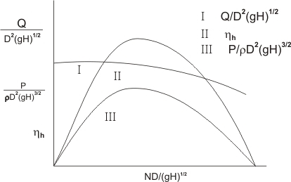 |
Fig.13: Performance characteristics of a reaction turbine (in dimensionless parameters) |
Figure 13 is one of the typical plots where variation in the efficiency of different reaction turbines with the rated power is shown.
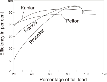 |
Fig.14: Variation of efficiency with load |
Key Takeaways:
- Performance curve: - A pump performance curve indicates how a pump will perform in regards to pressure head and flow. A curve is defined for a specific operating speed (rpm) and a specific inlet/outlet diameter.
References
1. Chow,V.T. “Open Channel hydraulics” McGraw Hill Publication
2. Subramanya, K., Flow through Open Channels, TMH, New Delhi
3. Ranga Raju, K.G., Flow through open channels, T.M.H. New Delhi
4. Rajesh Srivastava, Flow through Open Channels , Oxford University Press
5. Streeter, V.L.& White E.B., ”Fluid Mechanics” McGraw Hill Publication
6. Modi & Seth “Hydraulics & Fluid Mechanics” Standard Publications.
7. RK Bansal “Fluid Mechanics and Hydraulic Machines” Laxmi Publication
8. AK Jain “Fluid Mechanics” Khanna Publication.
9. Houghtalen, “Fundamentals of Hydraulics Engineering Systems” 4/e Pearson Education, Noida
