UNIT – 1
Simple stress and strains
Stress -
- When a material is subjected to an external force, a resisting force is set up in the component.
- The internal resistance force per unit area acting on a material is called the stress at a point. It is a tensor quantity having unit of N/m2 or Pascal.
Stress = |

- Force(F) is expressed in Newton (N)
- Original area (A), in square meters (m2)
- The stress σ will be expresses in N/m2. This unit is called Pascal (Pa).
- As Pascal is a small quantity, in practice, multiples of this unit is used.
1kPa =  Pa =
Pa =  N/m2
N/m2
1MPa = 106Pa = 106N/m2 = 1N/mm2
1GPa = 109Pa = 109N/m2
Strain –
- It is the deformation produced in the material due to simple stress.
- It usually represents the displacement between particles in the body relative to a reference length.
|

Key Takeaways-
- The internal resistance force per unit area acting on a material is called the stress at a point.
Stress = 
- Strain =
A) Types of Stress -
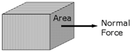
- Normal stress
Fig No 1.1 Normal Stress Normal Stress = |


- Shear Stress
|
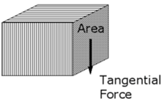
Fig No 1.2 Shear Stress
- Bulk Stress
|
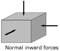
Fig No 1.3 Bulk Stress
Bulk Stress = |


Types of Strain –
- Normal Strain:
The normal strain of a body is generally expressed as the ratio of total displacement to the original length.
Normal Strain = |
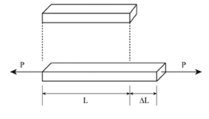

Fig 1.4 Normal Strain
- Since strain is m/m, it is dimensionless.
- It is of two types: Longitudinal strain and Lateral Strain
- The longitudinal strain is defined as the ratio of the change in length of the body due to the deformation to its original length in the direction of the force.
- The Lateral Strain is defined as the ratio of the change in length (breadth of a rectangular bar or diameter of a circular bar) of the body due to the deformation to its original length (breadth of a rectangular bar or diameter of a circular bar) in the direction perpendicular to the force.
Poisson’s Ratio ( |


- Shear strain
|
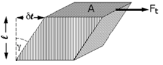
Fig No 1.5 Shear Strain
Note 1: The angle is radians, not degrees. The volume of the solid is not changed by shear strain.
Shear Strain =
|


- Bulk Strain or Volumetric Strain
|

Fig No. 1.6 Volumetric Strain
Bulk Strain =
|


Key Takeaways-
|


- According to Hook’s law the stress is directly proportional to strain i.e. normal stress (σ) ∝ normal strain (ε) and shearing stress ( ζ )∝ shearing strain ( γ ).
|
- The co-efficient E is called the modulus of elasticity i.e. its resistance to elastic strain. The coefficient
- G is called the shear modulus of elasticity or modulus of rigidity.
Key Takeaways
- σ = Eε and ζ = γG
(A) For Brittle Metal –
- The stress-strain diagram is shown in the figure. In brittle materials, there is no appreciable change in the rate of strain. There is no yield point and no necking takes place.
|
|
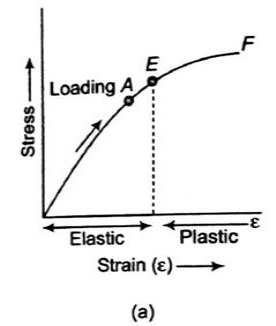
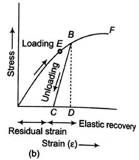
Fig No 1.7 Stress-Strain Diagram (Brittle Metal)
- In figure (a), the specimen is loaded only up to point A, when load has gradually removed the curve follows the same path AO and strain completely disappears. Such behavior is known as elastic behavior.
- In figure (b), the specimen is loaded up to point B beyond the elastic limit E. When the specimen has gradually loaded the curve follows path BC, resulting in a residual strain OC or permanent strain.
(B) For Ductile Metal –
- The true stress-strain curve is also known as the flow curve
|
Fig No 1.8 Stress-Strain Diagram (Ductile Metal)
- True stress-strain curve gives a true indication of deformation characteristics because it is based on the instantaneous dimension of the specimen.
- In engineering stress-strain curve, stress drops down after necking since it is based on the original area.
- In true stress-strain curve, the stress, however, increases after necking since the cross-sectional area of the specimen decreases rapidly after necking.
- The flow curve of many metals in the region of uniform plastic deformation can be expressed by the simple power law.
|

Key Takeaways
- True stress-strain curve gives a true indication of deformation characteristics because it is based on the instantaneous dimension of the specimen.
- The flow curve of many metals in the region of uniform plastic deformation can be expressed by the simple power law.
σT = K(εT)n
A) Lateral Strain –
- Lateral Strain is defined as the ratio of the change in length (breadth of a rectangular bar or diameter of a circular bar) of the body due to the deformation to its original length (breadth of a rectangular bar or diameter of a circular bar) in the direction perpendicular to the force.
B) Poisson’s Ratio –
- When a body is subjected to simple tensile stress within its elastic limits then there is a change in the dimensions of the body in the direction of the load as well as in the opposite direction.
- When these changed dimensions are divided with their original dimensions, longitudinal strain and lateral strain are obtained.
- The ratio of the lateral strain to the longitudinal strain is called Poisson’s ratio. It is represented by the symbol “µ”. Poisson’s ratio is maximum for an ideal elastic incompressible material and its value is 0.5.
- For most of the engineering materials, Poisson’s ratio lies between 0.25 and 0.33. It has no units.
(C) Volumetric Strain –
Bulk Strain =
|


|
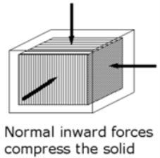
Fig No 1.9 Volumetric Strain
(D) Elastic Modulus –
Different elastic constants are as follows :
- Young’s modulus
- Bulk modulus
- Rigidity modulus
- Poisson’s ratio
- According to Hooke’s law, when a body is subjected to tensile stress or compressive stress, the stress applied is directly proportional to the strain within the elastic limits of that body.
- The ratio of applied stress to the strain is constant and is known as Young’s modulus or modulus of elasticity.
- Young’s modulus is denoted by letter “E”. The unit of modulus of elasticity is the same as the unit of stress which is mega pascal (mPa). 1 mPa is equal to 1 N/mm2.
|

|
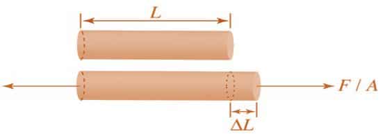
Fig 1.10: Body Subjected to Tensile Stress
- When a body is subjected to mutually perpendicular direct stresses which are alike and equal, within its elastic limits, the ratio of direct stress to the corresponding volumetric strain is found to be constant.
- This ratio is called bulk modulus and is represented by letter “K”. Unit of Bulk modulus is mPa.
|

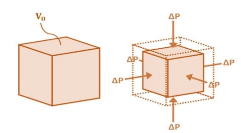
Fig1.11: Volumetric Change of Body
3. Rigidity Modulus
When a body is subjected to shear stress the shape of the body gets changed, the ratio of shear stress to the corresponding shear strain is called rigidity modulus or modulus of rigidity. It is denoted by the letters “G” or “C” or “N”. Unit of rigidity modulus is mPa.
Rigidity Modulus (G) = |
|

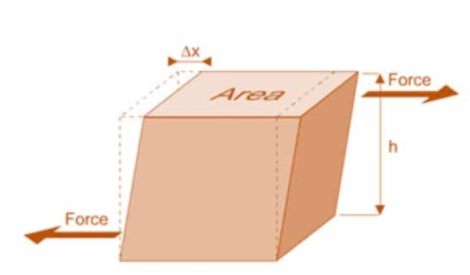
Fig 1.12: Shear Deformation of Body
- When a body is subjected to simple tensile stress within its elastic limits then there is a change in the dimensions of the body in the direction of the load as well as in the opposite direction.
- When these changed dimensions are divided with their original dimensions, longitudinal strain and lateral strain are obtained.
- The ratio of the lateral strain to the longitudinal strain is called Poisson’s ratio. It is represented by the symbol “µ”. Poisson’s ratio is maximum for an ideal elastic incompressible material and its value is 0.5.
- For most of the engineering materials, Poisson’s ratio lies between 0.25 and 0.33. It has no units.
Relationship between Elastic Constants
E = 2G (1 +
E = 3K (1
E =
E = |


Key Takeaways
|


A)Members in Series –
Temperature stress in Members in Parallel (composite section)
Consider a composite member formed by joining a steal rod and copper rod as strain in fig 1.
If both the materials are allowed to expand freely then change in length of copper will be  and in steel
 .
.
Let 
Refer fig-2
|
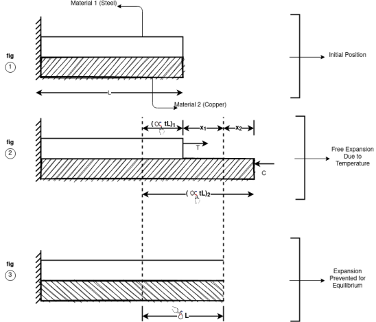
Fig.1.13
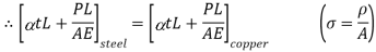
When equilibrium is reached the tensile force exerted by copper on steel will be equal to compressive force exerted by steel on copper Refer fig-3
For a composite section final deformation is same i.e., If  and temperature rises.
Compression in material 1 = Tensile in material 2
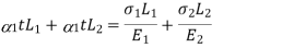
Total Elongation of steel = Total elongation of copper
Total strain Deformation |


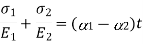


A) Members in Series –
Composite Member in Series
Consider a member ABL is held in support of A and C as shown in fig-1.
When temperature is raised compressive stresses are developed in each portion and when temperature is lowered tensile stresses are developed in each portion
|
Fig.1.14
Let  and
and  Young’s Modulus of portion 1 and 2
 Coefficient of linear Expansion in 1 and 2
|
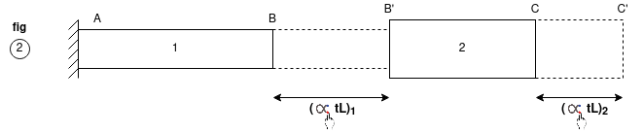
Fig.1.15
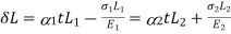
Free expansion due to Temperature Variation BB’ and CC’ is the free expansion of member 1 and 2 Free Expansion Let R be the Deformation due to reaction
Then Equation of compatibility Free Expansion – deformation due to reaction = 0 Free expansion = Deformation due to reaction
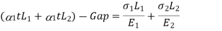
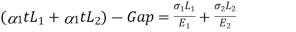
If supports are yields Free expansion due to temperature – Gap = Deformation due to reaction
|

Key Takeaways
|
(A) Composite Bar –
- A composite bar can be made of two bars of different materials rigidly fixed together so that both bars strain together under external load.
- As the strains in the two bars are same, the stresses in the two bars will be different and depend on their respective modulus of elasticity. A stiffer bar will share major part of external load.
- In a composite system the two bars of different materials may act as suspenders to a third rigid bar subjected to loading. As the change in length of both bars is the same, different stresses are produced in two bars.
(B) Temperature Stress –
- A composite bar is made up of two bars of different materials perfectly joined together so that during temperature change both the bars expand or contract by the same amount.
- Since the coefficient of expansion of the two bars is different thermal stresses are developed in both the bars.
Key Takeaways
- A composite bar can be made of two bars of different materials rigidly fixed together so that both bars strain together under external load.
- A composite bar is made up of two bars of different materials perfectly joined together so that during temperature change both the bars expand or contract by the same amount.
- Application of external loads to a member causes deformation of the member but the member has a natural tendency to oppose the deformation and in doing so it develops internal stresses.
- These internal stresses have the capacity to do work and as such, the member has energy stored in it. Thus work done upon a member in straining it is called as Strain Energy.
- Volume of bar= A.L Strain Energy when loading is gradually applied load to the member.
(A) Gradually Applied load –
- Let us consider a vertical bar of X-sectional area 'A' be rigidly held at one end and carry a gradually applied load at the other end as shown in fig.
Let δl be extension in length L
|
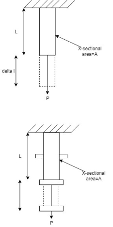
Fig No 1.16 Gradually Applied Load
- Strain energy stored in the member=world done by gradually applied load.
- Strain energy when loading is suddenly applied load to the member
(B) Suddenly Applied Load –
- Let the load P be suddenly applied. Let the extension of member be δl.
- In this case, the magnitude of load is constant throughout the process of extension.
- Let 'p' be the maximum stress included. Equating strain energy stored by the member to the work done.
- Hence, the maximum stress intensity due to a suddenly applied load is twice the stress intensity produced by the load of the same magnitude applied gradually.
- Strain Energy when loading is impacted load to the member.
(C) Impact load:
- In this case, the load P is dropped from a height h before it commences to stretch the bar.
- A vertical bar whose upper end is fixed at the top and collar is provided at the lower end.
- Load P drops by a height h on the collar and this extend the member by δl
- Let p=maximum stress intensity produced in the bar/ Hence extension at bar
Key Takeaways
- Strain energy stored in the member=world done by gradually applied load.
- The maximum stress intensity due to a suddenly applied load is twice the stress intensity produced by the load of the same magnitude applied gradually.
a) Normal Stress –
- A force which acts normal to a surface causes stress which also acts normal to that surface. Provided that the force passes through the centroid of the surface, then the stress will be uniform over the whole surface.
- This type of stress is known as a direct stress or normal stress.
b) Normal Strain –
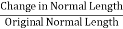
- A body subject to a direct stress will deform and be in a state of strain. The direct strain (E), which is measured in the same direction as the direct stress (cr), is given by the expression E= change in length of body (&L), original length of body (L) where both '&L and L are measured in the direction of the applied normal force (P).
Key Takeaways
- A force which acts normal to a surface causes stress which also acts normal to that surface. Provided that the force passes through the centroid of the surface, then the stress will be uniform over the whole surface. This type of stress is known as a direct stress or normal stress.
- A body subject to a direct stress will deform and be in a state of strain. The direct strain (E), which is measured in the same direction as the direct stress (cr), is given by the expression E= change in length of body (&L), original length of body (L) where both '&L and L are measured in the direction of the applied normal force (P).
a) Shear Stress –
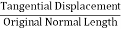
The shear stress is defined to be the ratio of the tangential force to the cross sectional area of the surface upon which it acts,
|

b) Shear Strain –
The shear strain is defined to be the ratio of the horizontal displacement to the height of the block,
α = δ x / h |
Key Takeaways
 = F tan / A
- α = δ x / h
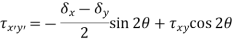
- To find the stresses in inclined plane in a stressed material we consider a general plane inclined at an angle to the known plane in an element and we find normal and tangential (shearing) stresses on this plane.
- The following three types of stressed condition in an element are considered.
- Uniaxial Direct Stresses
- Biaxial Direct Stresses
- General Two-Dimensional Stress System
Key Takeaways
- The following three types of stressed condition in an element are considered.
4. Uniaxial Direct Stresses
5. Biaxial Direct Stresses
6. General Two-Dimensional Stress System
a) Principal Stress –
- The plane carrying the maximum normal stress is called the major principal plane and normal stress is called major principal stress.
- The plane carrying the minimum normal stress is known as minor principal plane and normal stress is called minor principal stress.
|
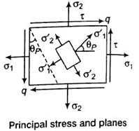
Fig No 1.17 Principal Stress
b) Principal Strain –
For two-dimensional strain system,
|


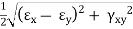
Where,
εx = Strain in x-direction
εy = Strain in y-direction
γxy = Shearing strain
Key Takeaways
- The plane carrying the maximum normal stress is called the major principal plane and normal stress is called major principal stress.
- For two-dimensional strain system,
|


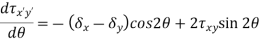
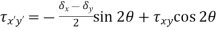
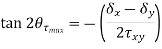
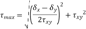
- Like the normal stress, the shear stress will also have a maximum at a given angle, θτ-max. This angle can be determined by taking a derivative of the shear stress rotation equation with respect to the angle and set equate to zero.
|


Key Takeaways
|


- Mohr's circle is a geometric representation of the two-dimensional stress state and is very useful to perform quick and efficient estimations.
- It is also popularly used in geotechnical fields such as soil strength, stress path, earth pressure and bearing capacity. It is often used to interpret the test data, to analyze complex geotechnical problems, and to predict soil behavior.
- The pole point on Mohr's circle is a point so special that it can help to readily find stresses on any specified plane by using diagram instead of complicated computation.
- There will be one plane on which normal stress value is maximum, this plane is known as Principal plane (more precisely maximum principal plane) and normal stress on this plane is known as principal stress (more precisely maximum principal stress). Similarly, there will be one more plane on which normal stress value is minimum, this is also a principal plane (minimum principal plane) and normal stress on this plane is known as Principal stress (minimum principal stress).
- Starting with a stress or strain element in the XY plane, construct a grid with a normal stress on the horizontal axis and a shear stress on the vertical. (Positive shear stress plots at the bottom.) Then just follow these steps:
- Plot the vertical face coordinates V (σxx , τxy).
- Plot the horizontal coordinates H (σyy, –τxy).
- Draw a diameter line connecting Points V (from Step1) and H (from Step2).
- Sketch the circle around the diameter from Step 3.
- Compute the normal stress position for the circle’s center point (C).
- Calculate the radius (R) for the circle.
- Determine the principal stresses σP1 and σP2.
- Compute the principal angles ΘP1 and ΘP2.
Key Takeaways-
- Mohr's circle is a geometric representation of the two-dimensional stress state and is very useful to perform quick and efficient estimations.
- It is also popularly used in geotechnical fields such as soil strength, stress path, earth pressure and bearing capacity. It is often used to interpret the test data, to analyze complex geotechnical problems, and to predict soil behavior.
Three-Dimensional State of Stress and Strains –
Normal stresses and strains in 3 dimension (Tri-axial loading)
|
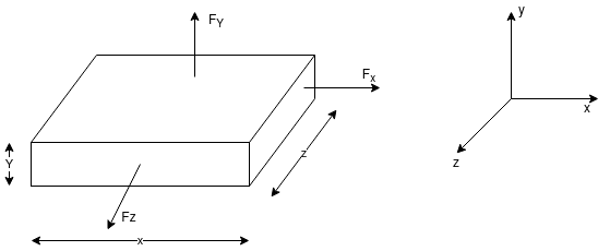
Fig.1.18
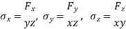
A body is said to be under tri-axial loading when it is subjected to three loads, which one mutually perpendicular in direction say x, y, z direction.
Consider a Rectangular specimen subjected to three tensile stresses, which are mutually perpendicular to each other as shown in fig
Let  be stresses in three dimensions (all stresses are Tensile).
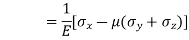
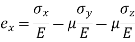
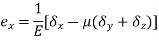
Strain in x - dimension
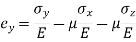
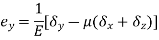
Strain in y - dimension
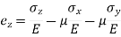
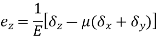
Strain in z - dimension
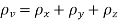
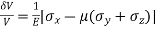
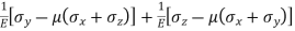
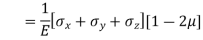
Volumetric Strain
|


Key Takeways
|


A three-dimensional case in which stresses act in the x, y, and z directions gives the following set of equations of equilibrium.
|


Key Takeaways-
- The following set of equations of equilibrium.
|


|
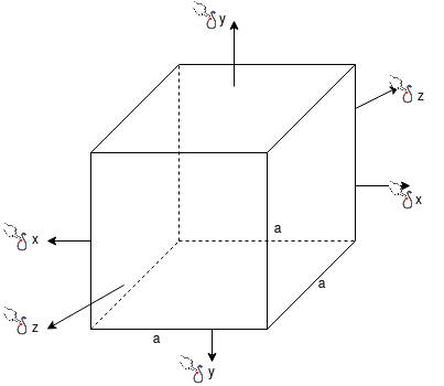
Fig.1.19
For three direction stress system
Strain in x – dimension
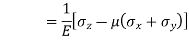
Strain in y - dimension
Strain in z - dimension
|

Key Takeaways-
|


- When a machine element is subjected to a system of complex stress system, it is important to predict the mode of failure so that the design methodology may be based on a particular failure criterion. Theories of failure are essentially a set of failure criteria developed for the ease of design.
- In machine design an element is said to have failed if it ceases to perform its function. There are basically two types of mechanical failure:
1. Yielding- This is due to excessive inelastic deformation rendering the machine part unsuitable to perform its function. This mostly occurs in ductile materials.
2. Fracture- in this case the component tears apart in two or more parts. This mostly occurs in brittle materials.
- There are many instances when a ductile material may fail by fracture. This may occur if a material is subjected to
(a) Cyclic loading
(b) Long term static loading at elevated temperature
(c) Impact loading
(d) Work hardening
(e) Severe quenching
Key Takeaways-
- There are basically two types of mechanical failure:
1. Yielding- This is due to excessive inelastic deformation rendering the machine part unsuitable to perform its function. This mostly occurs in ductile materials.
2. Fracture- in this case the component tears apart in two or more parts. This mostly occurs in brittle materials.
- There are many instances when a ductile material may fail by fracture. This may occur if a material is subjected to
(a) Cyclic loading
(b) Long term static loading at elevated temperature
(c) Impact loading
(d) Work hardening
(e) Severe quenching
- The ratio of ultimate to allowable load or stress is known as factor of safety i.e. The factor of safety can be denoted as the ratio of the material strength or failure stress to the allowable or working stress.
- The factor of safety must be always greater than unity.
- It is easier to refer to the ratio of stresses since this applies to material properties.
FOS = failure stress / working or allowable stress
Key Takeaways-
- The factor of safety must be always greater than unity.
- It is easier to refer to the ratio of stresses since this applies to material properties.
FOS = failure stress / working or allowable stress
References-
- Mechanics of Materials by Hibbeler,Pearson.
- Mechanics of Materials by Gere,Cengage Learning.
- Strength of Materials by Ryder,Macmillan.
- Mechanics of Materials by Patel, Cengage Learning.


