Unit - 3
Flexural Stresses and Torsions
- Pure bending (Theory of simple bending) is a condition of stress where a bending moment is applied to a beam without the simultaneous presence of axial, shear, or torsional forces.
- Pure bending occurs only under a constant bending moment (M) since the shear force (V), which is equal to
 = V, has to be equal to zero.
 - In reality, a state of pure bending does not practically exist, because such a state needs an absolutely weightless member. The state of pure bending is an approximation made to derive formulas.
Key Takeaways-
- Pure bending occurs only under a constant bending moment (M) since the shear force (V), which is equal to
 = V, has to be equal to zero.
- The material of the beam is homogeneous and isotropic.
- The value of Young's Modulus of Elasticity is same in tension and compression.
- The transverse sections which were plane before bending, remain plane after bending also.
- The beam is initially straight and all longitudinal filaments bend into circular arcs with a common centre of curvature.
- The radius of curvature is large as compared to the dimensions of the cross-section.
- Each layer of the beam is free to expand or contract, independently of the layer, above or below it.
Key Takeaways-
Assumptions-
- The material of the beam is homogeneous and isotropic.
- The value of Young's Modulus of Elasticity is same in tension and compression.
- The transverse sections which were plane before bending, remain plane after bending also.
- The beam is initially straight and all longitudinal filaments bend into circular arcs with a common centre of curvature.
- The radius of curvature is large as compared to the dimensions of the cross-section.
- Each layer of the beam is free to expand or contract, independently of the layer, above or below it
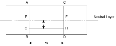
Derivation of Flexure formula for pure bending
Fig.1-Before bending
Consider any two normal sections AB and CD of a beam for a small length ‘dx’ apart as shown in fig. After the action of the transverse loading on the beam, the beam will be bends A’B’C’D’ as shown in fig. Below
Fig 2 -After bending |
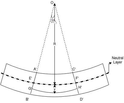
Let A’ B’ and C’ D’ intersect each other at O.
Let, R = Radius of curvature of Neutral layer FF. Θ = Subtended angle at o
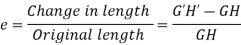
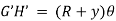
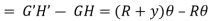
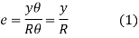
Consider a layer GH at a distance y from Neutral axis Strain in layer GH due to bending
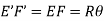
Let GH=EF
From fig-2
Length of arc = Subtended angle × Radius Original length Length of layer Change in length
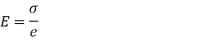
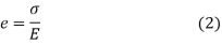
By definition, modulus of elasticity
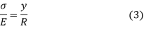
From Equation (1) and (2)
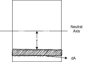
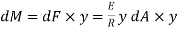
Since E and R are constant, the stress is directly proportional to the distance from Neutral axis. Now consider cross-section of the beam. Consider an elemented strip at ‘y’ from NA and Area of strip ‘dA’. Force on the strip = Stress on the strip × Area on the strip
Moment of this force about N.A
Total moment of whole section about N.A
But
From
This is known as Bending formula or Flexure formula. Key Takeaways- This is known as Bending formula or Flexure formula |


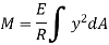


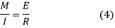


M = Internal bending moment about the section’s neutral axis y = Perpendicular distance from the neutral axis to a point on the section I = Moment of Inertia of the section area about the neutral axis
Where, c = Perpendicular distance from the neutral axis to the farthest point on the section Key Takeaways-
|


To calculate the section modulus, the following formula applies: Z = Where, I = moment of inertia, y = distance from centroid to top or bottom edge of the rectangle For symmetrical sections the value of Z is the same above or below the centroid. For asymmetrical sections, two values are found: Z max and Z min. Key Takeaways-
Z =
|


For a simple floor beam, I-sections are used.
M =
Therefore, M = z σ When beams are loaded, bending stresses are developed at all sections. The bending stresses developed in beams can be determined by the equation theory of simple bending. For laterally supported beams, the permissible bending stress in tension as well as in compression should not exceed σbc or σbt = 0.66fy For laterally unsupported beams, the permissible stress in bending compression is calculated by using tables from the IS code book (IS:800). Load carrying capacity of the Beam From structural steel tables for the given beam, the section modulus ( Depending upon whether the beam is laterally restrained or unrestrained; the value of permissible stress in bending compression (σbc) is calculated. The moment of resistance of the beam is found out. MR = Equating the moment of resistance to the maximum bending moment equation, the total load (w) the beam can carry is calculated. Key Takeaways-
MR = |


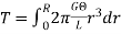
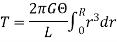
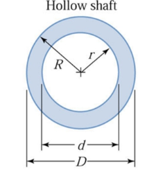
Torsion equation or torsion constant is defined as the geometrical property of a bar’s cross-section that is involved in the axis of the bar that has a relationship between the angle of twist and applied torque. The SI unit of Torsion equation is m4. The torsion equation is given as follows:
Where, T - torsional moment, N-mm J - polar moment of inertia, mm4 - shear stress in the element, N/mm2 r- distance of element from centre of shaft, mm G - modulus of rigidity, N/mm2 - angle of twist, rad L- length of shaft, mm
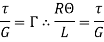
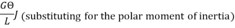
B) Derivation Consider a solid circular shaft with radius R that is subjected to a torque T at one end and the other end under the same torque. Angle in radius = Arc AB = RӨ = Lγ
Where, A and B: two fixed points on the circular shaft γ: angle subtended by AB
Where, 𝞃: shear stress γ: shear strain
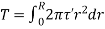
Consider a small strip of radius with thickness dr that is subjected to shear stress.
Where, r: radius of small strip dr: thickness of the strip γ: shear stress
Therefore, this equation is Torsion equation. C) Assumptions Following are the assumptions made for the derivation of torsion equation:
Key Takeaways- Therefore, this equation is Torsion equation
1) The material is homogeneous (elastic property throughout) 2) The material should follow Hook’s law 3) The material should have shear stress proportional to shear strain 4) The cross-sectional area should be plane 5) The circular section should be circular 6) Every diameter of the material should rotate through the same angle 7) The stress of the material should not exceed the elastic limit
|


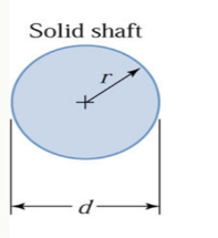
The expressions for the polar moments of circular areas are A) Solid Circular Shaft:
Fig.4 Solid shaft
B) Hollow Circular Shaft: Fig.4 Hollow shaft
Key Takeaways-
|


From the torsion equation, Angle of twist,
Where, T - Torsional moment, N-mm J - Polar moment of inertia, mm4 G - Modulus of rigidity, N/mm2 (sometimes denoted by C) - angle of twist, rad For a given specimen, the shaft properties like length L, polar modulus J and material properties like rigidity modulus G are constants and hence the angle of twist is directly proportional to the twisting moment or torque producing the twist. Torque producing twist in a shaft is similar to the bending moment producing bend or deflection in a beam. Similar to the flexural rigidity in beams expressed by EI, torsional rigidity is expressed as GJ which can be defined as the torque required to produce a twist of unit radian per unit length of the shaft. Key Takeaways-
|


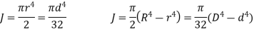
3.10 Combined Torsion and Bending of Circular Shafts
Fig 5. Combine Torsion and Bending
Important Note,
Key Takeaways-
|


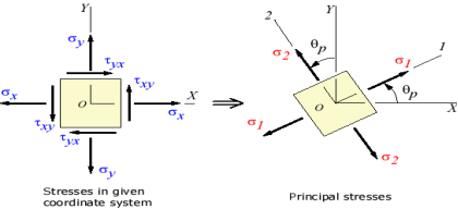
3.11 Principal Stress and Maximum Shear Stress
There exists an angle qp where the shear stress tx'y' becomes zero. That angle is found by setting tx'y' to zero in the above shear transformation equation and solving for q (set equal to qp). The result is,
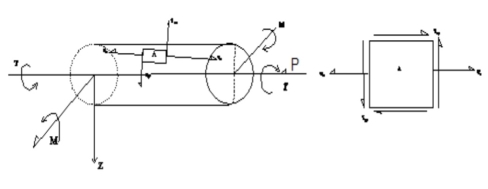
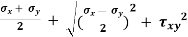
The angle qp defines the principal directions where the only stresses are normal stresses. These stresses are called principal stresses and are found from the original stresses (expressed in the x, y, z directions) via,
The transformation to the principal directions can be illustrated as:
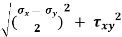
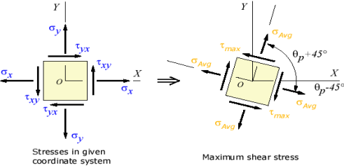
Fig 6. Principal Stress B) Maximum Shear Stress – Another important angle,
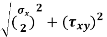
The maximum shear stress is equal to one-half the difference between the two principal stresses,
The transformation to the maximum shear stress direction can be illustrated as:
Fig 7. Maximum Shear Stress Part C) Shear Stresses –
Key Takeaways-
|


|
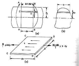
Fig.8
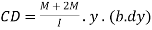
Consider, an elemental length of a beam between the section AA and BB separated by a distance Let the moments acting at AA and BB be M and M+dm respectively. Let CD be a fibre fo thickness dy at a distance y from the neutral axis. Then bending stress of left side of the fibre
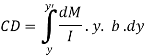
Force on the left side of the layer Therefore, unbalanced force, towards right on the layer CD is There are a number of such elements above the section CD Hence the unbalanced horizontal force above the section,
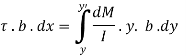
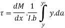
This horizontal force is resisted by the resisting force provided by shearing stresses acting horizontal on the plane at CD. Let the intensity of shear stress be
Where, Where the term But the term Substituting in the expression
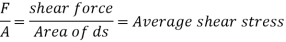
Where F = Shear force at a section in a beam a = Area above or below a fibre
I = M.I of the entire section about the N.A b= breadth of the fibre |


Shear Stress variation of some standard cross sections –
A) Rectangular Section
Fig.9 Rectangular Section |
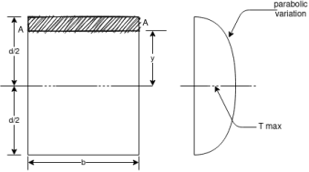
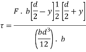
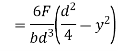
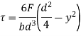
Consider a rectangular section of width b and depth d subjected to shearing force F. Let AA be a fibre at a distance y from the NA Where
And
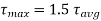
Thus the shear stress variation is parabolic when (i) at (ii) at (iii)
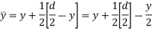
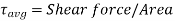
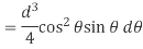
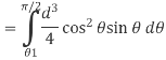
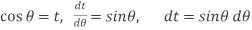
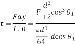
B) Circular Section Consider a circular section of diagram d as shown in fig. Let AA be a fibre at a vertical distance y and angle from NA on which shear stress is to be determined. To find moment of area above the fibre AA about the N.A. Consider an element of thickness dz at a vertical distance z from the N.A Let the angular distance of the element be θ Area of element A=b.dx
Width of the element
Fig.10 Circular Section Area of the element
Moment of area of the element about the N.A=A×Z
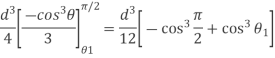
Therefore moment of the entire area, above the fibre AA about the N.A = a
If
Moment of inertia of the section Substituting in the expression for shear stress
Where b=width of the fibre AA =
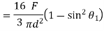
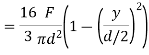
Hence shear stress varies parabolically over the depth. Its value is zero at the extreme fibres where
Thus in circular sections shear stress is maximum at the centre and is equal to 4/3 times the average stress
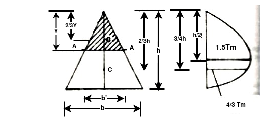
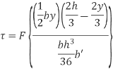
C) Triangular Section
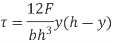
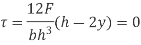
Fig.11 Triangular Section Let AA be a fibre distance y from the top. Shear stress in general
i) at ii) at At the centroid
Or
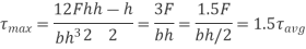
Thus maximum shear stress occurs at the half the depth and its value is 1.5 times the average shear stress in the case of an isosceles triangle.
Key Takeaways-
(i) at (ii) at (iii) |


References-
- Mechanics of Materials by Hibbeler,Pearson.
- Mechanics of Materials by Gere,Cengage Learning.
- Strength of Materials by Ryder,Macmillan.
- Mechanics of Materials by Patel, Cengage Learning.


