Unit - 4
Deflection of Beams
A) Slope –
- It is angular shift at any point of the beam between no load condition and loaded beam.
- Its value is different at different points on the length of the beam.
- It is represented by dy/dx or θ.
- Its unit is radians.
- There is a maximum limit for slope for any loaded beam.
B) Deflection –
- It is the vertical shift of a point on the beam between no load condition and loaded beam.
- Its value is different at different points on the length of the beam.
- It is represented by y or 𝜹.
- Its units are mm.
- There is a limit for maximum deflection for any loaded beam.
Key Takeaways-
- Slope is angular shift at any point of the beam between no load condition and loaded beam.
- Deflection is the vertical shift of a point on the beam between no load condition and loaded beam.
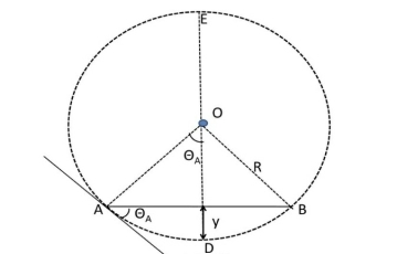
Let, L = Span of Beam M = Bending Moment R = Radius of curvature of beam after bending Y = Deflection of beam at centre
Fig No 4.1
From the above figure, AC
In practice, deflection of beam y is very small and square of y is negligible.
By using Bending Formula,
Put the value of R in eq. no 1, we get
From the geometry of fig.
Since,
Key Takeaways- is the Relationship Between Moment, Slope and Deflection
|


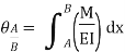
4.3.1 Theorem 1 – The change in slope between any two points on the elastic curve equals the area of the M/EI (moment) diagram between these two points.
Where, M = Moment EI = Flexural Rigidity
A, B = Points on Elastic curve
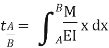
4.3.2 Theorem 2 – The vertical deviation of a point A on an elastic curve with respect to the tangent which is extended from another point B equals the moment of the area under the M/EI diagram between those two points (A and B). This moment is computed about point A where the deviation from B to A is to be determined.
Where, M = Moment EI = Flexural Rigidity
A, B = Points on Elastic curve
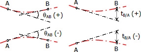
4.3.3 Rules of Sign Convention –
4.3.4 Procedure of Analysis – The following procedure provides a method that may be used to determine the displacement and slope at a point on the elastic curve of a beam using the moment-area theorem.
Key Takeaways-
The change in slope between any two points on the elastic curve equals the area of the M/EI (moment) diagram between these two points.
The vertical deviation of a point A on an elastic curve with respect to the tangent which is extended from another point B equals the moment of the area under the M/EI diagram between those two points (A and B). This moment is computed about point A where the deviation from B to A is to be determined. |


- When the beam is subjected to point loads (but several loads) this is very convenient method for determining the deflection of the beam.
- In this method we will write single moment equation in such a way that it becomes continuous for entire length of the beam in spite of the discontinuity of loading.
- After integrating this equation, we will find the integration constants which are valid for entire length of the beam. This method is known as method of singularity constant.
4.4.1 Procedure of Analysis –
Step – I:
Calculate all reactions and moments.
Step – II:
Write down the moment equation which is valid for all values of x. This must contain brackets.
Step – III:
Integrate the moment equation by a typical manner. Integration of (x-a) will be  not
not  and integration of
  will be
  and so on.
Step – IV:
After first integration write the first integration constant (A) after first terms and after second time integration write the second integration constant (B) after A.x. Constant A and B are valid for all values of x.
Step – V:
Using Boundary condition find A and B at a point x = p if any term in Macaulay’s method, (x-a) is negative (-ve) the term will be neglected.
Key Takeaways-
1. Procedure of Analysis –
Step – I:
Calculate all reactions and moments.
Step – II:
Write down the moment equation which is valid for all values of x. This must contain brackets.
Step – III:
Integrate the moment equation by a typical manner. Integration of (x-a) will be  not
not  and integration of
  will be
  and so on.
Step – IV:
After first integration write the first integration constant (A) after first terms and after second time integration write the second integration constant (B) after A.x. Constant A and B are valid for all values of x.
Step – V:
Using Boundary condition find A and B at a point x = p if any term in Macaulay’s method, (x-a) is negative (-ve) the term will be neglected.
A) Buckling –
- Buckling is the sudden change in shape (deformation) of a structural component under load, such as the bowing of a column under compression or the wrinkling of a plate under shear.
- If a structure is subjected to a gradually increasing load, when the load reaches a critical level, a member may suddenly change shape and the structure and component is said to have buckled.
B) Stability –
- Stability is the ability of the structure to support a specified load without undergoing unacceptable (or sudden) deformations.
Key Takeaways-
- Buckling is the sudden change in shape (deformation) of a structural component under load, such as the bowing of a column under compression or the wrinkling of a plate under shear.
- Stability is the ability of the structure to support a specified load without undergoing unacceptable (or sudden) deformations.
- The ratio of the effective length of a column to the least radius of gyration of its cross section is called the slenderness ratio (sometimes expressed with the Greek letter lambda, λ).
- This ratio affords a means of classifying columns and their failure mode.
- The slenderness ratio is important for design considerations. All the following are approximate values used for convenience.
Key Takeaways-
- The ratio of the effective length of a column to the least radius of gyration of its cross section is called the slenderness ratio (sometimes expressed with the Greek letter lambda, λ).
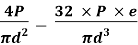
σ = σ = P/A + M/Z
Fig No 4.2 Combined Bending and Direct Stress
The stress distribution form face A to face B as shown in the figure.
Fig No 4.3 Stress Distribution Note: 1.Eccentric load produces direct stress as well as bending stress. 2. If direct stress is more than bending stress ( 3.If direct stress is equal to bending stress ( 4.If direct stress is less than bending stress ( 5.Hence for no tensile stress in the section, the direct stress will be greater than or equal to bending stress.
Key Takeaways-
|


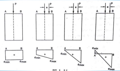


Fig No 4.4 Rectangular Column
Key Takeaways-
|


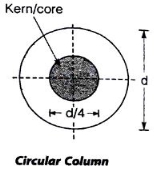
Fig No 4.5 Circular Column
Key Takeaways-
|


References-
- Mechanics of Materials by Hibbeler,Pearson.
- Mechanics of Materials by Gere,Cengage Learning.
- Strength of Materials by Ryder,Macmillan.
- Mechanics of Materials by Patel, Cengage Learning.
Unit - 4
Deflection of Beams
A) Slope –
- It is angular shift at any point of the beam between no load condition and loaded beam.
- Its value is different at different points on the length of the beam.
- It is represented by dy/dx or θ.
- Its unit is radians.
- There is a maximum limit for slope for any loaded beam.
B) Deflection –
- It is the vertical shift of a point on the beam between no load condition and loaded beam.
- Its value is different at different points on the length of the beam.
- It is represented by y or 𝜹.
- Its units are mm.
- There is a limit for maximum deflection for any loaded beam.
Key Takeaways-
- Slope is angular shift at any point of the beam between no load condition and loaded beam.
- Deflection is the vertical shift of a point on the beam between no load condition and loaded beam.
Let, L = Span of Beam M = Bending Moment R = Radius of curvature of beam after bending Y = Deflection of beam at centre
Fig No 4.1
From the above figure, AC
In practice, deflection of beam y is very small and square of y is negligible.
By using Bending Formula,
Put the value of R in eq. no 1, we get
From the geometry of fig.
Since,
Key Takeaways- is the Relationship Between Moment, Slope and Deflection
|


4.3.1 Theorem 1 – The change in slope between any two points on the elastic curve equals the area of the M/EI (moment) diagram between these two points.
Where, M = Moment EI = Flexural Rigidity
A, B = Points on Elastic curve
4.3.2 Theorem 2 – The vertical deviation of a point A on an elastic curve with respect to the tangent which is extended from another point B equals the moment of the area under the M/EI diagram between those two points (A and B). This moment is computed about point A where the deviation from B to A is to be determined.
Where, M = Moment EI = Flexural Rigidity
A, B = Points on Elastic curve
4.3.3 Rules of Sign Convention –
4.3.4 Procedure of Analysis – The following procedure provides a method that may be used to determine the displacement and slope at a point on the elastic curve of a beam using the moment-area theorem.
Key Takeaways-
The change in slope between any two points on the elastic curve equals the area of the M/EI (moment) diagram between these two points.
The vertical deviation of a point A on an elastic curve with respect to the tangent which is extended from another point B equals the moment of the area under the M/EI diagram between those two points (A and B). This moment is computed about point A where the deviation from B to A is to be determined. |


- When the beam is subjected to point loads (but several loads) this is very convenient method for determining the deflection of the beam.
- In this method we will write single moment equation in such a way that it becomes continuous for entire length of the beam in spite of the discontinuity of loading.
- After integrating this equation, we will find the integration constants which are valid for entire length of the beam. This method is known as method of singularity constant.
4.4.1 Procedure of Analysis –
Step – I:
Calculate all reactions and moments.
Step – II:
Write down the moment equation which is valid for all values of x. This must contain brackets.
Step – III:
Integrate the moment equation by a typical manner. Integration of (x-a) will be  not
not  and integration of
  will be
  and so on.
Step – IV:
After first integration write the first integration constant (A) after first terms and after second time integration write the second integration constant (B) after A.x. Constant A and B are valid for all values of x.
Step – V:
Using Boundary condition find A and B at a point x = p if any term in Macaulay’s method, (x-a) is negative (-ve) the term will be neglected.
Key Takeaways-
1. Procedure of Analysis –
Step – I:
Calculate all reactions and moments.
Step – II:
Write down the moment equation which is valid for all values of x. This must contain brackets.
Step – III:
Integrate the moment equation by a typical manner. Integration of (x-a) will be  not
not  and integration of
  will be
  and so on.
Step – IV:
After first integration write the first integration constant (A) after first terms and after second time integration write the second integration constant (B) after A.x. Constant A and B are valid for all values of x.
Step – V:
Using Boundary condition find A and B at a point x = p if any term in Macaulay’s method, (x-a) is negative (-ve) the term will be neglected.
A) Buckling –
- Buckling is the sudden change in shape (deformation) of a structural component under load, such as the bowing of a column under compression or the wrinkling of a plate under shear.
- If a structure is subjected to a gradually increasing load, when the load reaches a critical level, a member may suddenly change shape and the structure and component is said to have buckled.
B) Stability –
- Stability is the ability of the structure to support a specified load without undergoing unacceptable (or sudden) deformations.
Key Takeaways-
- Buckling is the sudden change in shape (deformation) of a structural component under load, such as the bowing of a column under compression or the wrinkling of a plate under shear.
- Stability is the ability of the structure to support a specified load without undergoing unacceptable (or sudden) deformations.
- The ratio of the effective length of a column to the least radius of gyration of its cross section is called the slenderness ratio (sometimes expressed with the Greek letter lambda, λ).
- This ratio affords a means of classifying columns and their failure mode.
- The slenderness ratio is important for design considerations. All the following are approximate values used for convenience.
Key Takeaways-
- The ratio of the effective length of a column to the least radius of gyration of its cross section is called the slenderness ratio (sometimes expressed with the Greek letter lambda, λ).
σ = σ = P/A + M/Z
Fig No 4.2 Combined Bending and Direct Stress
The stress distribution form face A to face B as shown in the figure.
Fig No 4.3 Stress Distribution Note: 1.Eccentric load produces direct stress as well as bending stress. 2. If direct stress is more than bending stress ( 3.If direct stress is equal to bending stress ( 4.If direct stress is less than bending stress ( 5.Hence for no tensile stress in the section, the direct stress will be greater than or equal to bending stress.
Key Takeaways-
|


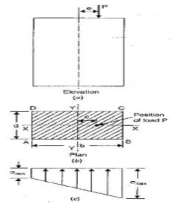


Fig No 4.4 Rectangular Column
Key Takeaways-
|
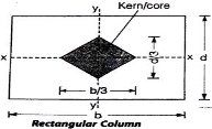


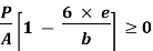


Fig No 4.5 Circular Column
Key Takeaways-
|


References-
- Mechanics of Materials by Hibbeler,Pearson.
- Mechanics of Materials by Gere,Cengage Learning.
- Strength of Materials by Ryder,Macmillan.
- Mechanics of Materials by Patel, Cengage Learning.


