Unit - 5
Helical and Leaf Spring
A) Helical Spring
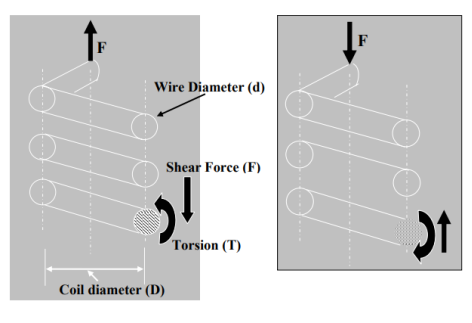
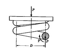
- The figures below show the schematic representation of a helical spring acted upon by a tensile load F (Fig.1(a)) and compressive load F (Fig.1(b)). The circles denote the cross section of the spring wire. The cut section, i.e. from the entire coil somewhere we make a cut, is indicated as a circle with shade.
Fig 1 (a) Fig 1 (b) |
- If we look at the free body diagram of the shaded region only (the cut section) then we shall see that at the cut section, vertical equilibrium of forces will give us force, F as indicated in the figure.
- This F is the shear force. The torque T, at the cut section and it’s direction is also marked in the figure. There is no horizontal force coming into the picture because externally there is no horizontal force present.
- So from the fundamental understanding of the free body diagram one can see that any section of the spring is experiencing a torque and a force. Shear force will always be associated with a bending moment.
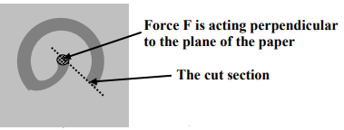
- However, in an ideal situation, when force is acting at the Centre of the circular spring and the coils of spring are almost parallel to each other, no bending moment would result at any section of the spring (no moment arm), except torsion and shear force. The Fig.2 will explain the fact stated above.
Fig.2 |
- Leaf Spring
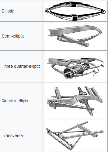
- A leaf spring is a simple form of spring commonly used for the suspension in wheeled vehicles. Originally called a laminated or carriage spring, and sometimes referred to as a semi-elliptical spring, elliptical spring, or cart spring.
- A leaf spring takes the form of a slender arc-shaped length of spring steel of rectangular cross-section. In the most common configuration, the center of the arc provides location for the axle, while loops formed at either end provide for attaching to the vehicle chassis.
- For very heavy vehicles, a leaf spring can be made from several leaves stacked on top of each other in several layers, often with progressively shorter leaves.
- Leaf springs can serve locating and to some extent damping as well as springing functions. While the interleaf friction provides a damping action, it is not well controlled and results in stiction in the motion of the suspension. For this reason, some manufacturers have used mono-leaf springs.
- A leaf spring can either be attached directly to the frame at both ends or attached directly at one end, usually the front, with the other end attached through a shackle, a short swinging arm.
- The shackle takes up the tendency of the leaf spring to elongate when compressed and thus makes for softer springiness. Some springs terminated in a concave end, called a spoon end (seldom used now), to carry a swiveling member.
|
Fig.3
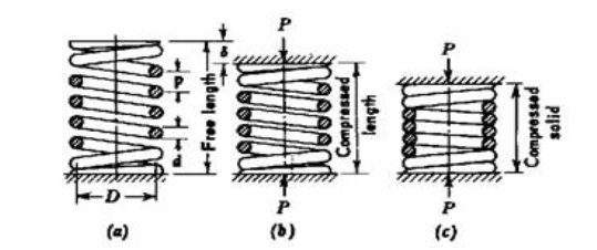
5.1.1 Deflection of springs by energy method
- Let
 is the axial deflection.
 - Then, work done by the load =

- Equating the work done to the strain energy stored in the spring,
= |
Key Takeaways
- A leaf spring can either be attached directly to the frame at both ends or attached directly at one end, usually the front, with the other end attached through a shackle, a short swinging arm.
- work done by the load =


Fig.4
Fig.5 |
5.2 Axial Load and twisting moment acting simultaneously both for open and both coiled springs
- Closed coiled
Fig.6
Fig.7 |
Fig.8 |
Closed - coiled helical spring subjected to an axial load :
|
Closed - coiled helical spring subjected to an axial moment
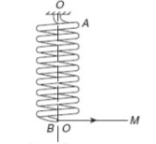
Fig 8 shows a close = coiled Helical spring subjected to an axial couple M. the effect of the couple is to rotate end B of the spring with respect to end n.
Helix angle X is very small.
ϕ is the total angle through which one end of the spring is turned relative to the other , when couple M is applied.
Work done on spring = (½) Mϕ .
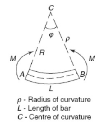
Fig 9 shows a b AB of Lenght subjected to Bending moment M
rϕ = L
ϕ = L/r , Where r = Radius of Curavature.
From Flexure Formula
 =
= 
∴ ϕ = 
L = 2nπR , I = 
∴ ϕ =  *64 =
*64 = 
∴ δ =  =
= 
B) Open coiled
|
Fig.9
|
Fig.10
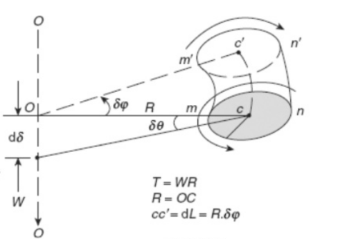
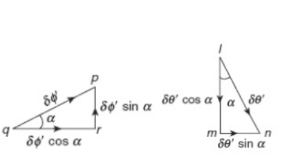
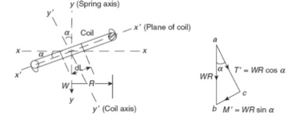
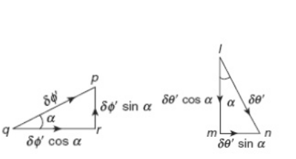
Say, an open-coiled Helical Spring of mean coil Radius R is subjected to an axial load W. WR = Total moment on spring wire WR cos α = T' = Twisting moment on a small element of length dl at the centers of coil WR sin α = M' = B.M. on small element of length dl in the place of coil. Due to twisting moment T' there will be angular twist δϕ' & due to B.M. M' , there will be an angular rotation δϕ' . δϕ' has two components δϕ' cos α & δϕ' sin α. δθ = Angular twist about XX axis = δϕ' cos α + δϕ' sin α. δϕ = angular rotation about Y Y axis = mm - qr = δϕ' sin α - δϕ' cos α.
Moreover , δϕ' =
Total angular Twist θ, about XX-axis.
θ = 0∫L δθ = 0∫L
= 0∫L(
Angular Twist θ = (
L = 2πnRsecα , put in above equation.
Axial deflection , δ = Rθ .
δ = 2πWR2secα (
Total Angular rotation about Y Y-axis
ϕ = 0∫L δθ = 0∫L (
An open- coiled helical spring of mean coil radius R, Helix angle α & number of turns n is subjected to an axial moment m as shown in fig. Components of M are M' = M cos α = bending moment & T' = M sin α = Twisting moment δθ' = Angular Twist due to T' δθ' = δϕ = Angular rotation due to M' about y' y' axis = δθ = Angular Twist about xx-axis = δ ϕ ' sin α - δ ϕ ' cos α. Δθ = (
Total angular Twist . θ = ∫δθ = 0∫L M sin α cos α( L = 2 π n R sec α ∴ ϕ (Total Angular Rotation) = 2π n R sec α( Key Takeaways
Axial deflection δ =
∴ δ = |
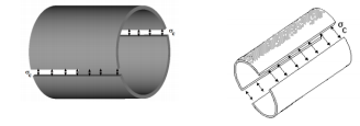
- If the wall thickness is less than about 7% of the inner diameter then the cylinder may be treated as a thin one. Thin walled cylinders are used as boiler shells, pressure tanks, pipes and in other low pressure processing equipment’s.
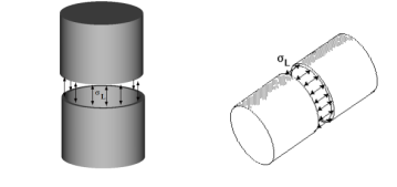
- In general three types of stresses are developed in pressure cylinders viz.circumferential or hoop stress, longitudinal stress in closed end cylinders and radial stresses.
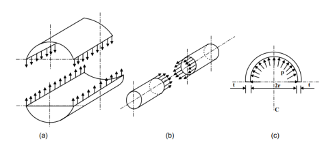
- These stresses are demonstrated in figure-11
Fig.11 (a) Circumferential stress (b) Longitudinal stress and (c) Radial stress developed in thin cylinders. |
- In a thin walled cylinder the circumferential stresses may be assumed to be constant over the wall thickness and stress in the radial direction may be neglected for the analysis.
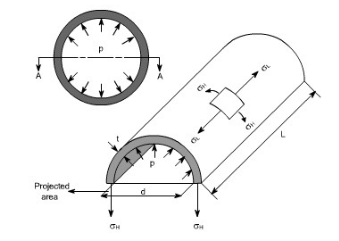
- Considering the equilibrium of a cut out section the circumferential stress σθ and longitudinal stress σz can be found. Consider a section of thin cylinder of radius r, wall thickness t and length L and subjected to an internal pressure p as shown in figure-11(a).
Key Takeaways
- Thin walled cylinders are used as boiler shells, pressure tanks, pipes and in other low pressure processing equipment’s.
Thick cylindrical shell
1) The radial pressure ‘px’ (compressive) 2) The hoop stress fx (tensile) 3) The longitudinal tensile stress po(tensile)
Thin spherical shells
Key Takeaways
The maximum shear stress,
The strain in any direction is given by
|
- The distinction between thin vs. thick wall pressure vessels is determined by the ratio between the mean radius of the vessel and the thickness of the wall.
- If this ratio is greater than 10, the vessel is considered a thin wall pressure vessel. If the ratio is less than 10, the vessel is considered a thick wall pressure vessel.
 Means Thin wall P.V.
- In operation, in a thin wall pressure vessel, stresses developed in the (thin) wall can conservatively be assumed to be uniform.
- These are the stresses students are familiar calculating using ASME Section I PG-27 or Section VIII Div. I UG-27. In fact, most of the pressure vessels powers engineers will work with are of a thin-wall type.
- In contrast, a thick wall pressure vessel develops a greater (circumferential) stress on the inside surface of the vessel and it reduces towards the outside diameter.
|
Key Takeaways
|
Thin walled cylinders
- A cylinder is regarded as thin walled when the wall thickness t is less than 1/20 of the diameter D. When the wall is thicker than this, it is regarded as a thick wall and it is treated differently as described later. Consider a cylinder of mean diameter D, wall thickness t and length L.
- When the pressure inside is larger than pressure outside by P,the cylinder tend to split along a length and along a circumference as shown in fig.13 and fig. 14
|
F = Equating eqn 1 and 2
Now consider the forces trying to split the cylinder along a length. The force due to pressure is So long as the material holds this is balanced by the stress in the material. The Force due to the stress is F = Equating (4) and (5) we have It follows that for a given pressure the circumferential stress is twice the Longitudinal stress. |
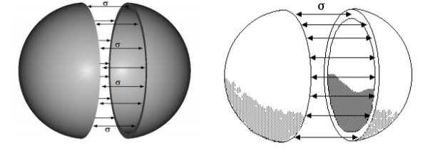
Thin walled spheres
- A sphere will tend to split about a diameter as shown in fig.15
Key Takeaways
The stress produced in the material is equivalent to the longitudinal stress in the cylinder so
|
|
- Circumferential or Hoop Stress: This is the stress which is set up in resisting the bursting effect of the applied internal pressure and can be most conveniently treated by considering the equilibrium of the cylinder.
- The hoop stress is the force exerted circumferentially (perpendicular both to the axis and to the radius of the object) in both directions on every particle in the cylinder wall.
- The effect of this may split the pipe into two halves. The failure of the pipe in two halves in fact is possible across any plane, which contains diameter and axis of the pipe.
- Elements resisting this type of failure would be subjected to stress and direction of this stress is along the circumference.
|
- Longitudinal Stress: Consider a cylinder that could have closed ends and contain a fluid under a gauge pressure. Then the walls of the cylinder will have a longitudinal stress as well as a circumferential stress.
- Considering that the pipe ends are closed and pipe is subjected to an internal pressure ‘P’ the pipe may fail. Elements resisting this type of failure would be subjected to stress and direction of this stress is parallel to the longitudinal direction of the pipe.
- Radial stress: Radial stress can also be a factor in thick-walled pipe. It is stress in directions coplanar with, but perpendicular to, the symmetry axis. The radial stress is equal and opposite of the gauge pressure on the inside surface, and zero on the outside surface.
- The classic equation for hoop stress created by an internal pressure on a thin wall cylindrical pressure vessel is: σθ = PDm /2t for the Hoop Stress. Thin Wall Pressure Vessel Hoop Stress Calculator. Where: P = is the internal pressure
t = is the wall thickness.
- The hoop stress is the force exerted circumferentially (perpendicular to the axis and the radius of the object) in both directions on every particle in the cylinder wall. It can be described as:

Where:
F is the force exerted circumferentially on an area of the cylinder wall that has the following two lengths as sides,
t is the radial thickness of the cylinder,
l is the axial length of the cylinder.
- An alternative to hoop stress in describing circumferential stress is wall stress or wall tension (T), which usually is defined as the total circumferential force exerted along the entire radial thickness.

- Along with axial stress and radial stress, circumferential stress is a component of the stress tensor in cylindrical coordinates.
- It is usually useful to decompose any force applied to an object with rotational symmetry into components parallel to the cylindrical coordinate’s r, z, and θ. These components of force induce corresponding stresses: radial stress, axial stress, and hoop stress, respectively.
Key Takeaways
- Longitudinal Stress: Consider a cylinder that could have closed ends and contain a fluid under a gauge pressure. Then the walls of the cylinder will have a longitudinal stress as well as a circumferential stress.
- Radial stress: Radial stress can also be a factor in thick-walled pipe. It is stress in directions coplanar with, but perpendicular to, the symmetry axis. The radial stress is equal and opposite of the gauge pressure on the inside surface, and zero on the outside surface.
- An alternative to hoop stress in describing circumferential stress is wall stress or wall tension (T), which usually is defined as the total circumferential force exerted along the entire radial thickness.

Two-Dimensional Volumetric Strain
Using the strain transformation formulae, it will be verified that these quantities remain unchanged under any rotation of axes. The first of these has a very significant physical interpretation. Consider the deformation of the material element shown in . The volumetric strain is
If the strains are small, the term
Three Dimensional Volumetric Strain
The volumetric strain is:
=
And the squared and cubed terms can be neglected because of the small-strain assumption. Key Takeaways
=
|
- For thick cylinders such as guns, pipes to hydraulic presses, high pressure hydraulic pipes the wall thickness is relatively large and the stress variation across the thickness is also significant. In this situation the approach made in the previous section is not suitable.
- The problem may be solved by considering an axisymmetric about z-axis and solving the differential equations of stress equilibrium in polar co-ordinates.
- In general the stress equations of equilibrium without body forces can be given as
for Axis symmetry about z-axis
In a plane stress situation if the cylinder ends are free to expand σz=0 due to uniform radial deformation and symmetry zrz = zθz = zθr
the equation of equillibrium reduces to
This can be written in the following form of :
r
If we consider a general case with body forces such centrifugal forces in the case of a rotating cylinder or disc then the equation reduces to
which may be written as
r
it is convinient to solve the general equation so that the variety of problems may be solved
the strains Er & Eθ may be given by
Er = |
Eθ =
|
Combining equation 5 & 6 we have
r
Now from eqn 4 we may write
& combinig this with eqn 7 we may arrive at
For a non rotating thick cylinder with internal & external pressure pi &po we substitute w=0
In eqn 3 & this gives
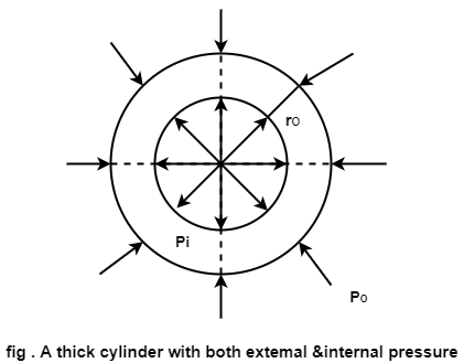
A typical case is shown in fig. A standard soln for eqn 9 is Substitute this in eqn 9 & also combinig with equtaion 3 we have δ r = c1 +
δ 0 = c1 -
where c1 and c2 are constant
Boundary conditions for thick cylinder with internal and external pressure pi and p0 respectively are: at r = ri , δ i = - pi at r = r0 , δ 0 = p0
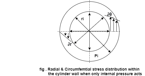
the radial stress δ r & circumferential stress δ θ are now given by
δ r =
δ 0 =
∴ δ r =
δ 0 =
fig Radius & circumferential stress distribution within the cylinder wall when only internal pressure acts.
Key Takeaways
|
- Another method of pre-stressing is to use compound (or composite) cylinders two or more cylinders which are assembled with interference fit.
- The analysis which follows is elastic since the method does not generally involve yielding - and may be applied to sleeves pressed onto shafts, etc.
- Two open cylinders only are considered. They are shown in exaggerated fashion both before assembly (individually completely free), and after assembly and pressurizing (ie. after all load components have been applied).
- The bore of the outer cylinder and the outside diameter of the inner cylinder are made to the same nominal common diameter Dc - however there is a known small diametral interference, Δ << Dc.
- The cylinders are then assembled concentrically using heat or force, and loaded by pressures internal and external to the assembly, pi and po respectively.
- Before safety of either cylinder can be addressed, the common interface pressure pc must be known. But the problem is statically indeterminate since statics reveals only that if pc exists as a contact pressure internal to the outer cylinder, then the inner cylinder is pressurized externally by the same amount.
- Geometric compatibility and the cylinders' constitutive laws ( xi) must be invoked. If the common diameter Dc increases by δi measured on the inner cylinder as sketched, and by δo measured on the outer, then compatibility requires that Δ = δo – δi
Key Takeaways
- Geometric compatibility and the cylinders' constitutive laws ( xi) must be invoked. If the common diameter Dc increases by δi measured on the inner cylinder as sketched, and by δo measured on the outer, then compatibility requires that Δ = δo – δi
- The bore of the outer cylinder and the outside diameter of the inner cylinder are made to the same nominal common diameter Dc - however there is a known small diametral interference, Δ << Dc.
References-
- Mechanics of Materials by Hibbeler,Pearson.
- Mechanics of Materials by Gere,Cengage Learning.
- Strength of Materials by Ryder,Macmillan.
- Mechanics of Materials by Patel, Cengage Learning.
