Measurement of temperature

Figure 1. A bead thermistor
The principle here is that a small change in resistance corresponds with a large change of temperature. For example, consider an LED that brightens and dims as the ambient temperature changes.
Thermistors have a large change in resistance with just a small change of temperature. To illustrate this concept, see Figure below, which shows the typical curve of a thermistor:
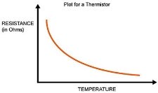
Figure 2. NTC
When the temperature rises, the resistance lowers. This is the main property of Negative Temperature Coefficient resistors (NTC).
Thermistors are also available as Positive Temperature Coefficient (PTC). PTCs work in a way that as the temperature rises, the resistance increases. However, note that PTC thermistors have a sort of tipping point and can greatly affect the resistance at some temperatures, making the PTC thermistor a bit more challenging with which to interface. Because of this, most low-cost temperature measurements utilize NTC thermistors.
Key Take-Aways:
Thermistors are widely used to measure temperature as a thermistor thermometer is a much different liquid and ambient air environment.
The thermocouple working principle is based on the Seeback Effect. This effect states that when a closed circuit is formed by joining two dissimilar metals at two junctions, and junctions are maintained at different temperatures then an electromotive force (e.m.f.) is induced in this closed circuit.
The amount of induced e.m.f. is different for different metal combinations and is proportional to the temperature difference of the junctions. This is the basic thermocouple working principle.
Working
Here the ‘P’ junction is the measuring junction or hot junction whereas the junction ‘Q’ is the reference junction or cold junction. And a PMMC instrument is connected in this arrangement as shown in Figure.
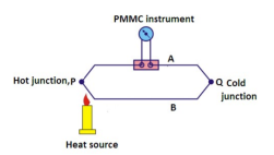
Figure 3. Thermocouple
These junctions are kept at different temperatures the cold junction is kept at 0oC and the measuring junction is kept at an unknown temperature which we want to measure.
An e.m.f. will be generated in this circuit due to the temperature difference of the junctions. This e.m.f. is in the order of millivolts. The e.m.f.is measured with the help of a PMMC instrument by connecting the circuit as shown in Figure.
When both the junctions are at the same temperature, e.m.f. generated at both junctions will be the same. No current will flow through the circuit. And there will be no deflection in the meter.
When both the junctions are at different temperatures, a current will flow through the meter. And the meter will show the deflection.
As the generated e.m.f. is proportional to the temperature difference, the amount of current flow will also be proportional to the temperature difference. And therefore, the meter can be calibrated directly in terms of temperature.
To reduce inaccuracies, most thermocouples are installed with instruments that provide automatic reference compensation.
The e.m.f. generated in a thermocouple is given by:
E = a(∆θ) + b(∆θ)2
∆θ = difference in temperature between two junctions (in oC)
a, b = constants generally, ‘a’ is very large as compare to ‘b’ so ‘b’ can be neglected.
Therefore, the above expression can be approximated as under:
E = a(∆θ). ∆θ = E/a .
RTD :
An RTD consists of a resistance element and insulated copper wires. The most common number of wires is 2; however, some RTDs have 3 or 4 wires. The resistive element is the temperature sensing element of the RTD. It is usually platinum because as a material it is highly stable over time, it has a wide temperature range, it offers an almost linear relationship between temperature and resistance and it has a chemical inertness. Nickle or copper are also other popular choices of material for the resistive element.
An RTD works by using a basic principle; as the temperature of a metal increases, so does the resistance to the flow of electricity. An electrical current is passed through the sensor, the resistance element is used to measure the resistance of the current being passed through it. As the temperature of the resistance element increases the electrical resistance also increases. The electrical resistance is measured in Ohms.
Key Take-Aways:
RTDs are limited to a maximum temperature of 1000 degrees Fahrenheit whereas certain thermocouples can be used to measure up to 2700 degrees Fahrenheit.
All objects emit infrared energy (heat) as a function of their temperature. The infrared energy emitted by an object is known as a heat signature.
In general, the hotter an object is, the more radiation it emits. A thermal image known as a thermal camera is a heat sensor that can detect tiny temperature differences.
The device collects the infrared radiation from objects in the scene and creates an electronic image based on information about the temperature differences. Because objects are rarely precisely the same temperature as other objects around them, a thermal camera is used to detect them, and they will appear as distinct in a thermal image.
Key Take-Aways:
Thermal imaging is a method of improving the visibility of objects in a dark environment by detecting the objects' infrared radiation and creating an image based on that information.
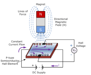
Figure 4. Hall effect sensor
Hall Effect Sensors consists of a thin piece of a rectangular p-type semiconductor material such as gallium arsenide (GaAs), indium antimonide (InSb), or indium arsenide (InAs) passing a continuous current through itself. When the device is placed within a magnetic field, the magnetic flux lines exert a force on the semiconductor material which deflects the charge carriers, electrons, and holes, to either side of the semiconductor slab.
This movement of charge carriers is a result of the magnetic force they experience while passing through the semiconductor material.
When these electrons and holes move sidewards a potential difference is produced between the two sides of the semiconductor material by the build-up of these charge carriers. Then the movement of electrons through the semiconductor material is affected by the presence of an external magnetic field which is at right angles to it and this effect is greater in a flat rectangular shaped material.
The effect of generating a measurable voltage by using a magnetic field is called the Hall Effect. To generate a potential difference across the device the magnetic flux lines must be perpendicular, (90o) to the flow of current and must be of correct polarity, generally a south pole.
Key Take-Aways:
A Hall-effect sensor (or simply Hall sensor) is a device to measure the magnitude of a magnetic field. Its output voltage is directly proportional to the magnetic field strength through it.
Inductive
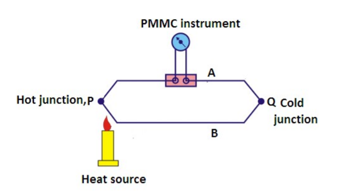
Figure 5. Inductive proximity sensor.
Inductive sensors operate based on Faraday’s Law. Faraday’s Law states that a change in magnetic flux in a coil of wire induces a voltage in the nearby coil. This is applied in inductive proximity sensors in the following way:
The sensor itself contains an oscillator circuit and a coil where an electromagnetic field radiates out and induces eddy currents in nearby metallic objects. The eddy currents have the effect of attenuating the oscillations from the amplifier. This reduction in oscillations is registered in the presence of a metallic object.
Because the metallic objects have inductive properties, inductive sensors can’t be used to detect plastic or cardboard, or other non-metallic objects. In general, inductive proximity sensors are suited for shorter-range applications as the inductive effect wears off with growing distance between the sensor and object to be detected.
Capacitive
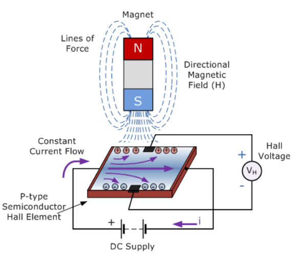
Figure 6. Capacitive proximity sensor
The capacitive proximity sensors operate by noting a change in the capacitance read by the sensor. A typical capacitor consists of two conductive elements called plates separated by insulating material which can be ceramic, plastic, paper, or other materials.
The way the capacitive proximity sensor works is that one of the conductive elements, or plates, is inside the sensor itself and the other one is the object to be sensed. The internal plate is connected to an oscillator circuit that generates an electric field. The air gap between the internal plate and the external object serves as the insulator or dielectric material. When an object is present, the capacitance value changes and gets registered as the presence of the object.
Use of Proximity sensor as accelerometer and vibration sensor
Accelerometer
The phone uses an accelerometer to detect any tilt in the phone to the side and change the display orientation accordingly. Accelerometers detect movement in three dimensions.
A proximity sensor uses some kind of wave to detect the presence of nearby objects without touching them. For example automatic doors and some other everyday applications.
Vibration sensor
The vibration sensor is also called a piezoelectric sensor. These sensors are flexible devices used for measuring various processes. This sensor uses the piezoelectric effect while measuring the changes within acceleration, pressure, temperature, force otherwise strain by changing to an electrical charge. This sensor is also used for deciding fragrances within the air by immediately measuring capacitance as well as quality.
Key Take-Aways:
Proximity sensors detect the presence or absence of objects using electromagnetic fields, light, and sound.
Ultrasonic flow sensor
Ultrasonic flow sensors operate using two slightly different approaches. In the first approach, a pair of ultrasonic transducers generate a signal that is directed into the fluid flow from two locations. Each signal generated by a transmitter is reflected to the receiver of the other transducer by a set of mirrors. The orientation of the transducers and mirrors is such that one signal is traveling for part of its path with the fluid flow while the other is traveling against the fluid flow. The receiver electronics measures the transit time of each signal and computes the time difference between the two. When the fluid is not in motion, the transit times are the same for each signal – when the fluid is moving, the signal that is moving with the flow will have a shorter transit time, therefore the difference between the two signal transit times reflects the velocity of the fluid. These types of ultrasonic flow sensors are sometimes called transit time ultrasonic flow sensors.
In a second variation of the design, ultrasonic energy is transmitted into the fluid and is reflected a receiver. Under the zero-flow condition, the frequency of the ultrasonic wave is unchanged. When the fluid is in motion, there is a frequency shift that occurs because of the Doppler effect, which is linear with respect to the fluid velocity. Detecting and reporting the shift in ultrasonic frequency allows for the computation of the fluid’s flow rate.
Laser flow sensor
The Laser Flow velocity sensor remotely measures flow in open channels with non-contact Laser Doppler Velocity technology and non-contact Ultrasonic Level technology. The sensor uses advanced technology to measure velocity with a laser beam at single or multiple points below the surface of the wastewater stream.
The sensor uses an ultrasonic level sensor to measure the level and determines a sub-surface point to measure velocity. The sensor then focuses its laser beam at this point and measures the frequency shift of the returned light.
Key Take-Aways:
Flow sensors is an electronic device that measures or regulates the flow rate of liquids and gasses within pipes and tubes
Ultrasonic level sensors
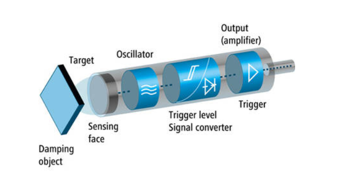
Figure 7. Ultrasonic level sensors
Ultrasonic sensors measure level by measuring the distance from the transmitter to the surface of a process material located below inside the vessel or tank. The time for the sound wave to travel back and forth the process material surface is used to calculate this distance which is interpreted by the transmitter electronics as process level.
The transmitter electronics module contains all the power, computation, and signal processing circuits and an ultrasonic transducer consists of one or more piezoelectric crystals for the transmission and reception of the sound waves. When electrical energy is applied to the piezoelectric crystals, they move to produce a sound signal. When the sound signal is reflected, the movement of the reflected sound wave generates an electrical signal this is detected as the return pulse. The transit time, which is measured as the time between the transmitted and return signals, is then used to infer the level of a vessel. The basic design of an ultrasonic instrument is shown above.
Capacitive flow sensor
When the liquid is introduced near the electrodes of the capacitor, the capacitance changes progressively, and the liquid level is determined. To measure variations in capacitance, electric energy flowing into and out of the electrodes is measured as the circuit potential is varied.
A regular flow of energy is established by connecting the electrodes to an alternating current measurement circuit. The more energy flow to the electrodes, the greater the capacitance, meaning more liquid between the electrodes.
Proper sensor calibration requires taking reference measurements at empty and full. Generally, we need to know the dielectric constant of the liquid being measured to calibrate the capacitive level sensor at its full condition. Once the empty and full outputs are established, liquid level sensing comes to relating sensor output to these values.
Key Take-Aways:
A level sensor is a device that is designed to monitor, maintain, and measure liquid and sometimes solid levels.
Measurement of temperature

Figure 1. A bead thermistor
The principle here is that a small change in resistance corresponds with a large change of temperature. For example, consider an LED that brightens and dims as the ambient temperature changes.
Thermistors have a large change in resistance with just a small change of temperature. To illustrate this concept, see Figure below, which shows the typical curve of a thermistor:
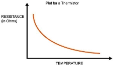
Figure 2. NTC
When the temperature rises, the resistance lowers. This is the main property of Negative Temperature Coefficient resistors (NTC).
Thermistors are also available as Positive Temperature Coefficient (PTC). PTCs work in a way that as the temperature rises, the resistance increases. However, note that PTC thermistors have a sort of tipping point and can greatly affect the resistance at some temperatures, making the PTC thermistor a bit more challenging with which to interface. Because of this, most low-cost temperature measurements utilize NTC thermistors.
Key Take-Aways:
Thermistors are widely used to measure temperature as a thermistor thermometer is a much different liquid and ambient air environment.
The thermocouple working principle is based on the Seeback Effect. This effect states that when a closed circuit is formed by joining two dissimilar metals at two junctions, and junctions are maintained at different temperatures then an electromotive force (e.m.f.) is induced in this closed circuit.
The amount of induced e.m.f. is different for different metal combinations and is proportional to the temperature difference of the junctions. This is the basic thermocouple working principle.
Working
Here the ‘P’ junction is the measuring junction or hot junction whereas the junction ‘Q’ is the reference junction or cold junction. And a PMMC instrument is connected in this arrangement as shown in Figure.
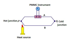
Figure 3. Thermocouple
These junctions are kept at different temperatures the cold junction is kept at 0oC and the measuring junction is kept at an unknown temperature which we want to measure.
An e.m.f. will be generated in this circuit due to the temperature difference of the junctions. This e.m.f. is in the order of millivolts. The e.m.f.is measured with the help of a PMMC instrument by connecting the circuit as shown in Figure.
When both the junctions are at the same temperature, e.m.f. generated at both junctions will be the same. No current will flow through the circuit. And there will be no deflection in the meter.
When both the junctions are at different temperatures, a current will flow through the meter. And the meter will show the deflection.
As the generated e.m.f. is proportional to the temperature difference, the amount of current flow will also be proportional to the temperature difference. And therefore, the meter can be calibrated directly in terms of temperature.
To reduce inaccuracies, most thermocouples are installed with instruments that provide automatic reference compensation.
The e.m.f. generated in a thermocouple is given by:
E = a(∆θ) + b(∆θ)2
∆θ = difference in temperature between two junctions (in oC)
a, b = constants generally, ‘a’ is very large as compare to ‘b’ so ‘b’ can be neglected.
Therefore, the above expression can be approximated as under:
E = a(∆θ). ∆θ = E/a .
RTD :
An RTD consists of a resistance element and insulated copper wires. The most common number of wires is 2; however, some RTDs have 3 or 4 wires. The resistive element is the temperature sensing element of the RTD. It is usually platinum because as a material it is highly stable over time, it has a wide temperature range, it offers an almost linear relationship between temperature and resistance and it has a chemical inertness. Nickle or copper are also other popular choices of material for the resistive element.
An RTD works by using a basic principle; as the temperature of a metal increases, so does the resistance to the flow of electricity. An electrical current is passed through the sensor, the resistance element is used to measure the resistance of the current being passed through it. As the temperature of the resistance element increases the electrical resistance also increases. The electrical resistance is measured in Ohms.
Key Take-Aways:
RTDs are limited to a maximum temperature of 1000 degrees Fahrenheit whereas certain thermocouples can be used to measure up to 2700 degrees Fahrenheit.
All objects emit infrared energy (heat) as a function of their temperature. The infrared energy emitted by an object is known as a heat signature.
In general, the hotter an object is, the more radiation it emits. A thermal image known as a thermal camera is a heat sensor that can detect tiny temperature differences.
The device collects the infrared radiation from objects in the scene and creates an electronic image based on information about the temperature differences. Because objects are rarely precisely the same temperature as other objects around them, a thermal camera is used to detect them, and they will appear as distinct in a thermal image.
Key Take-Aways:
Thermal imaging is a method of improving the visibility of objects in a dark environment by detecting the objects' infrared radiation and creating an image based on that information.
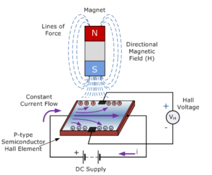
Figure 4. Hall effect sensor
Hall Effect Sensors consists of a thin piece of a rectangular p-type semiconductor material such as gallium arsenide (GaAs), indium antimonide (InSb), or indium arsenide (InAs) passing a continuous current through itself. When the device is placed within a magnetic field, the magnetic flux lines exert a force on the semiconductor material which deflects the charge carriers, electrons, and holes, to either side of the semiconductor slab.
This movement of charge carriers is a result of the magnetic force they experience while passing through the semiconductor material.
When these electrons and holes move sidewards a potential difference is produced between the two sides of the semiconductor material by the build-up of these charge carriers. Then the movement of electrons through the semiconductor material is affected by the presence of an external magnetic field which is at right angles to it and this effect is greater in a flat rectangular shaped material.
The effect of generating a measurable voltage by using a magnetic field is called the Hall Effect. To generate a potential difference across the device the magnetic flux lines must be perpendicular, (90o) to the flow of current and must be of correct polarity, generally a south pole.
Key Take-Aways:
A Hall-effect sensor (or simply Hall sensor) is a device to measure the magnitude of a magnetic field. Its output voltage is directly proportional to the magnetic field strength through it.
Inductive
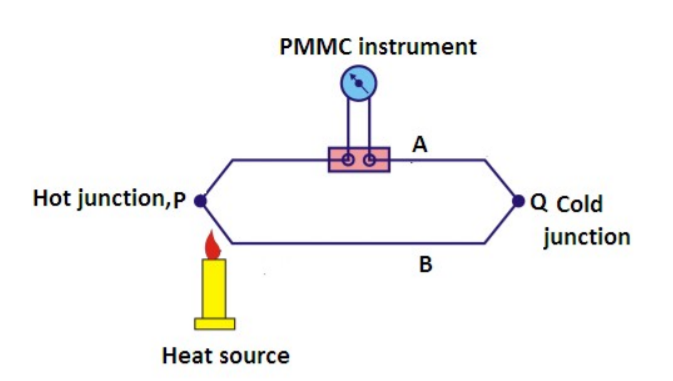
Figure 5. Inductive proximity sensor.
Inductive sensors operate based on Faraday’s Law. Faraday’s Law states that a change in magnetic flux in a coil of wire induces a voltage in the nearby coil. This is applied in inductive proximity sensors in the following way:
The sensor itself contains an oscillator circuit and a coil where an electromagnetic field radiates out and induces eddy currents in nearby metallic objects. The eddy currents have the effect of attenuating the oscillations from the amplifier. This reduction in oscillations is registered in the presence of a metallic object.
Because the metallic objects have inductive properties, inductive sensors can’t be used to detect plastic or cardboard, or other non-metallic objects. In general, inductive proximity sensors are suited for shorter-range applications as the inductive effect wears off with growing distance between the sensor and object to be detected.
Capacitive
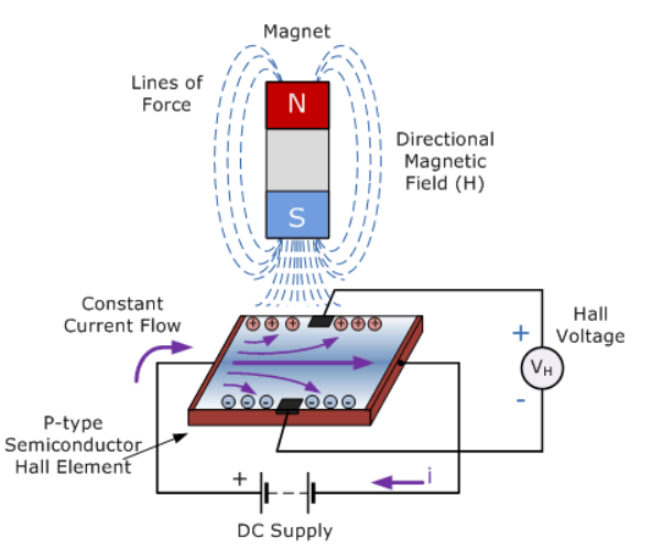
Figure 6. Capacitive proximity sensor
The capacitive proximity sensors operate by noting a change in the capacitance read by the sensor. A typical capacitor consists of two conductive elements called plates separated by insulating material which can be ceramic, plastic, paper, or other materials.
The way the capacitive proximity sensor works is that one of the conductive elements, or plates, is inside the sensor itself and the other one is the object to be sensed. The internal plate is connected to an oscillator circuit that generates an electric field. The air gap between the internal plate and the external object serves as the insulator or dielectric material. When an object is present, the capacitance value changes and gets registered as the presence of the object.
Use of Proximity sensor as accelerometer and vibration sensor
Accelerometer
The phone uses an accelerometer to detect any tilt in the phone to the side and change the display orientation accordingly. Accelerometers detect movement in three dimensions.
A proximity sensor uses some kind of wave to detect the presence of nearby objects without touching them. For example automatic doors and some other everyday applications.
Vibration sensor
The vibration sensor is also called a piezoelectric sensor. These sensors are flexible devices used for measuring various processes. This sensor uses the piezoelectric effect while measuring the changes within acceleration, pressure, temperature, force otherwise strain by changing to an electrical charge. This sensor is also used for deciding fragrances within the air by immediately measuring capacitance as well as quality.
Key Take-Aways:
Proximity sensors detect the presence or absence of objects using electromagnetic fields, light, and sound.
Ultrasonic flow sensor
Ultrasonic flow sensors operate using two slightly different approaches. In the first approach, a pair of ultrasonic transducers generate a signal that is directed into the fluid flow from two locations. Each signal generated by a transmitter is reflected to the receiver of the other transducer by a set of mirrors. The orientation of the transducers and mirrors is such that one signal is traveling for part of its path with the fluid flow while the other is traveling against the fluid flow. The receiver electronics measures the transit time of each signal and computes the time difference between the two. When the fluid is not in motion, the transit times are the same for each signal – when the fluid is moving, the signal that is moving with the flow will have a shorter transit time, therefore the difference between the two signal transit times reflects the velocity of the fluid. These types of ultrasonic flow sensors are sometimes called transit time ultrasonic flow sensors.
In a second variation of the design, ultrasonic energy is transmitted into the fluid and is reflected a receiver. Under the zero-flow condition, the frequency of the ultrasonic wave is unchanged. When the fluid is in motion, there is a frequency shift that occurs because of the Doppler effect, which is linear with respect to the fluid velocity. Detecting and reporting the shift in ultrasonic frequency allows for the computation of the fluid’s flow rate.
Laser flow sensor
The Laser Flow velocity sensor remotely measures flow in open channels with non-contact Laser Doppler Velocity technology and non-contact Ultrasonic Level technology. The sensor uses advanced technology to measure velocity with a laser beam at single or multiple points below the surface of the wastewater stream.
The sensor uses an ultrasonic level sensor to measure the level and determines a sub-surface point to measure velocity. The sensor then focuses its laser beam at this point and measures the frequency shift of the returned light.
Key Take-Aways:
Flow sensors is an electronic device that measures or regulates the flow rate of liquids and gasses within pipes and tubes
Ultrasonic level sensors
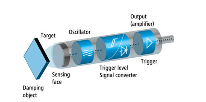
Figure 7. Ultrasonic level sensors
Ultrasonic sensors measure level by measuring the distance from the transmitter to the surface of a process material located below inside the vessel or tank. The time for the sound wave to travel back and forth the process material surface is used to calculate this distance which is interpreted by the transmitter electronics as process level.
The transmitter electronics module contains all the power, computation, and signal processing circuits and an ultrasonic transducer consists of one or more piezoelectric crystals for the transmission and reception of the sound waves. When electrical energy is applied to the piezoelectric crystals, they move to produce a sound signal. When the sound signal is reflected, the movement of the reflected sound wave generates an electrical signal this is detected as the return pulse. The transit time, which is measured as the time between the transmitted and return signals, is then used to infer the level of a vessel. The basic design of an ultrasonic instrument is shown above.
Capacitive flow sensor
When the liquid is introduced near the electrodes of the capacitor, the capacitance changes progressively, and the liquid level is determined. To measure variations in capacitance, electric energy flowing into and out of the electrodes is measured as the circuit potential is varied.
A regular flow of energy is established by connecting the electrodes to an alternating current measurement circuit. The more energy flow to the electrodes, the greater the capacitance, meaning more liquid between the electrodes.
Proper sensor calibration requires taking reference measurements at empty and full. Generally, we need to know the dielectric constant of the liquid being measured to calibrate the capacitive level sensor at its full condition. Once the empty and full outputs are established, liquid level sensing comes to relating sensor output to these values.
Key Take-Aways:
A level sensor is a device that is designed to monitor, maintain, and measure liquid and sometimes solid levels.