Unit-2
Geometric Design
The features of the cross-section of the pavement influence the life of the pavement as well as the riding comfort and safety.
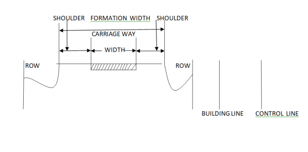
Fig.1: Cross-section of Roads
Key Takeaways:
- Surface protection (especially for gravel and bituminous roads)
- Subgrade protection (by proper drainage)
- Quick-drying of pavement which in turn increases safety
Surface Type | Heavy Rain | Light Rain |
Concrete/Bituminous | 2% | 1.7% |
Gravel/WBM | 3% | 2.5% |
Earthen | 4% | 3% |
- Excessive camber will cause a transverse tilt of the vehicle making it uncomfortable for passengers. Also, the distribution of load to different wheels will not be uniform, leading to uneven wear and tear of wheels and damage to pavements.
- With excessive camber, heavy rain will result in the formation of heavy cross ruts.
- The central seeking tendency of vehicles will increase to avoid transverse tilt.
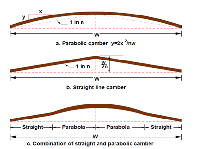
- Parabolic Camber
- Straight Line Camber
- Combination of Straight and Parabolic Camber
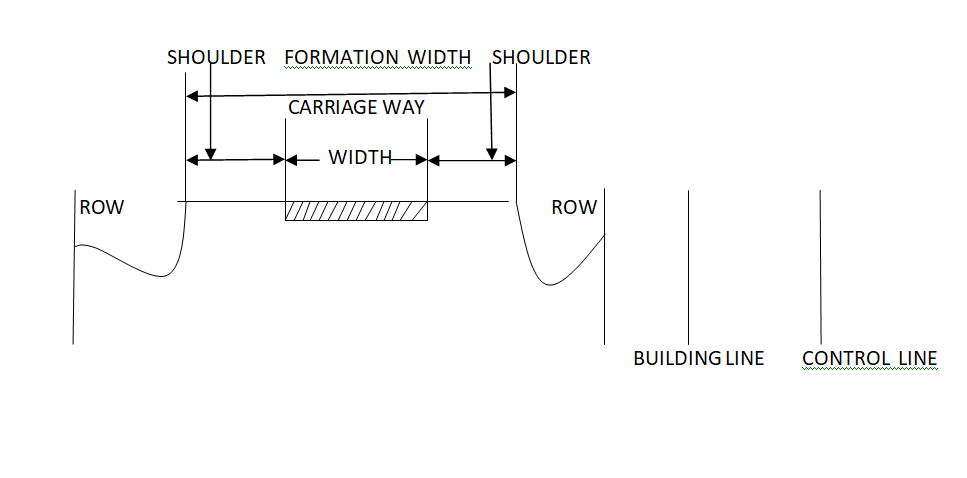
Fig.2: Types of camber
Key Takeaways:
Shoulders are provided along the road edge and are intended for accommodation of stopped vehicles, serve as an emergency lane for vehicles, and provide lateral support for base and surface courses.

Shoulders support the carriageway.
Minimum width of 2.5 m is recommended for 2-lane rural highways in India.
Key Takeaways:
The safe and efficient operation of vehicles on the road depends very much on the visibility of the road ahead of the driver. Thus the geometric design of the road should be done such that any obstruction on the road length could be visible to the driver from some distance ahead. This distance is said to be the sight distance.
For straight road on level ground, there is no problem of side distance. But Straight road on level ground is a rare case. Horizontal curves, vertical curves (Summit), intersections are potential places where there could be a restriction in terms of Sight distance
The actual distance along the road surface over which a driver from a specified height above the carriageway has visibility of the stationary or moving object.
The sight distance used for design are
Stopping Sight Distance (SSD) or absolute minimum sight distance
Intermediate Sight Distance (ISD) = 2*SSD
Overtaking Sight Distance (OSD) for safe overtaking
Headlight Sight Distance = SSD at night
Key takeaways:
2.5.1 Forces acting on a Vehicle on Horizontal Curve


Overturning:


 = Resistance Against Overturning


Lateral Skid: Can be avoided by increasing friction at curves

P=F
P =f*W


f: Coefficient of Lateral Friction = 0.15
Key Takeaways: -
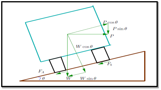
Fig.3: Vehicle on a sloping road

2.6.1 Equilibrium Super elevation or Balanced S.E.

2.6.2 Maximum and Minimum Super elevation [IRC]
Terrain | emax |
Plain and Rolling Terrain | 7% |
Hilly Terrain [Snow Bound] | 7% |
Hilly Terrain [Not Bound by Snow] | 10% |
2.6.3 (3/4)th Design Speed Assumption
Type | Plain | Rolling | Hilly | Steep |
NH & SH | 100-80 | 80-65 | 50-40 | 40-30 |
MDR | 80-65 | 65-50 | 40-30 | 30-20 |
ODR | 65-50 | 50-40 | 30-25 | 25-20 |
VR | 50-40 | 40-35 | 25-20 | 25-20 |

 [Given by IRC based on terrain or topography]
- IRC recommends the coefficient of lateral friction as 0.15.
- Friction factor also depends on various factors like
- Speed of vehicle
- Type and condition of the road surface.
- Type and condition of a vehicle tyre
2.6.5 Super elevation with or without Transition Curves
2.6.6 Ruling and Minimum Radius of Horizontal Curves:

3. Absolute Minimum radius Rmin based on ruling design speed vmin

2.6.7 Attainment of Super elevation

Fig.4: Outer edge rotation
- After a full rotation, we have a slope at the outer edge equal to the camber. But in between, for a small length of the road, the cross slope is less than camber.
- Drainage problem in outer half and outer edge in that portion may be damaged easily.
b. Crown Shifted Outward

Fig.5: Crown Shifted
- Large negative Super elevation on the outer half
- Drivers tend to run the vehicle along with the shifted crown.
2. Rotation of Pavement to attain full Super elevation:
- Depressing the inner edge and raising the outer edge each by half the total amount (E) of Super elevation.
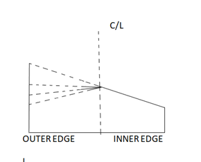
Fig.6: Rotation with respect to the center line
- Earthwork is balanced (cut and fill balanced)
- The vertical profile remains unchanged.
- Drainage problem because of depressing the inner edge below the general level.
b. Rotation w.r.t. Inner Edge:
- Additional earth filling.
- The centerline of the road is also raised, so the vertical alignment of the road is also changed.
c. Rotation w.r.t. Outer Edge:
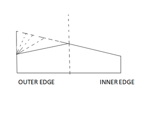
Fig.7: Rotation with respect to the outer edge
2.6.8 Steps Involved in Super elevation Calculation:
Basic Super elevation Equation: 
For Mixed Traffic Condition,

If ecal>emax, provide emaxand proceed with step 3 & 4.

If the value of f thus calculated is less than 0.15, then OK, else calculate the restricted speed as given in step 4.


Either restrict or reduce the speed or provide a better or more radius of the horizontal curve.
Key Takeaways:

Where,
Wm = Mechanical Widening
n = Number of Lanes
R = Radius of Curve

Key Takeaways:
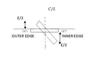
Fig.8: Transition Curve
2.8.1 Necessity of Transition Curve
2.8.2 Different Types of Transition Curves:
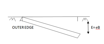
Fig.9: Different transition curve
2.8.3 Ideal Shape of Transition Curves:


B. Based on Rate of Change of Super elevation:
- Plain and Rolling Terrain: 1 in 150
- Mountainous or Steep Terrain: 1 in 60
Ls = N * E
= N* eB
B: Width of Pavement depending on the method of rotation of pavement.
Ls = N *e*(w+we)_____[ Pavement Rotation w.r.t. Inner Edge]
w: Normal width of Pavement
we: Extra Widening on a circular curve
1 in N: rate of change of Superelevation
C. Empirical Formula Based on the Recommended Maximum Rate of Change of Super elevation:

V: Speed in KMPH
ii. Mountainous and Steep or Hilly Terrain

The shift of Curve 
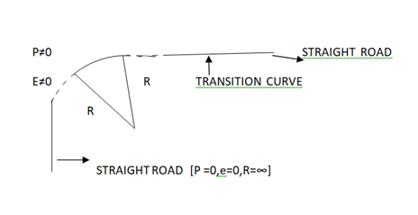
Fig.10: Different gradient
2.8.6 Types of Gradient
Terrain | Ruling Gradient |
Plain and Rolling Terrain | 1 in 30 |
Mountainous Terrain | 1 in 20 |
Steep Terrain | 1 in 16.7 |
- Topography
- Cost
Ruling < Gradient | Limiting < Gradient | Exceptional < Gradient | Minimum Gradient |
Key Takeaways:
- Summit Curves
- Valley Curves
Key takeaways:

Fig.11: Summit curve
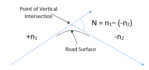
Summit Curves are formed when two gradients meet as illustrated below:
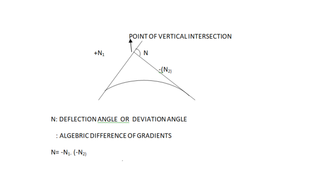
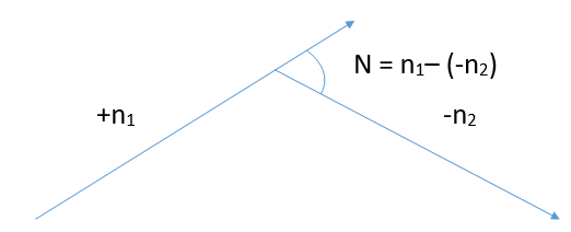
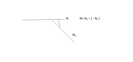

Fig.12: Different Grades Curve
1. Shape of Summit Curve
2. Design Considerations
P: Centrifugal Force
W: Gravitational Force
3. Length of Summit Curve (IRC Approach):
- When the length of the curve is greater than the sight distance (L>S)
- When the length of the curve is greater than the sight distance. ((L<S)
Case 1: L>S
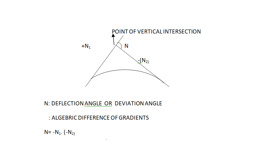
Fig.13: When L> S

Where,
- (S: OSD/ISD – when an obstruction is moving)
Case 2: L<S

Fig.14: When L < S

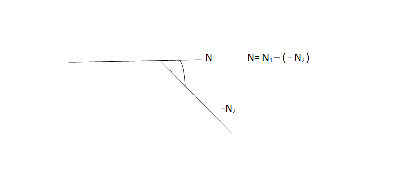
Fig.15: Valley Curve
Valley Curves are formed when two gradients meet as illustrated below:
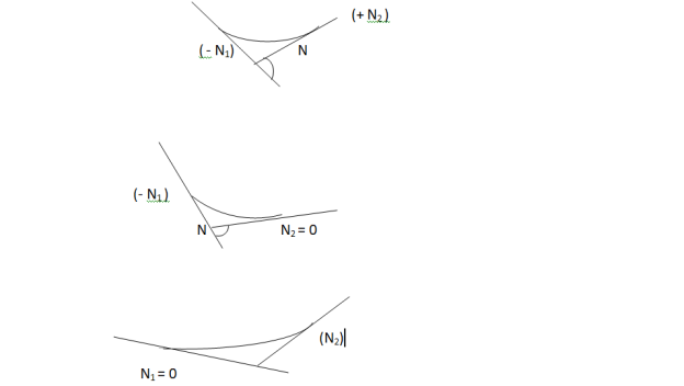
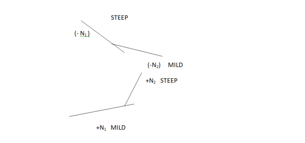
Fig.16: Different Grades
2.10.5 Length of Valley Curve (IRC Approach):
- Comfort Criteria
- Safety Criteria

Where,
B. Safety or Headlight Sight Distance Criteria
- When the length of the curve is greater than stopping sight distance (L>S)
- When the length of the curve is greater than stopping sight distance. ((L<S)
Case 1: L>S

Where,
Case 2: L<S

Key Takeaways:
References:
1. L.R. Kadiyali, Transportation Engineering, Khanna Publishing House
2. Saxena, Subhash C, A Textbook of Highway and Traffic Engineering, CBS Publishers &Distributors, New Delhi
3. Kumar, R Srinivasa, “A Textbook of Highway Engineering”, Universities Press,Hyderabad.
4. Kumar, R Srinivasa, “Pavement Design”, Universities Press, Hyderabad.
5. Chakraborty Partha& Das Animesh., “Principles of Transportation Engineering”,Prentice Hall (India), New Delhi,
6. IRC: 37- Latest revision, “Tentative Guidelines for the design of Flexible Pavements”Indian Roads Congress, New Delhi
7. IRC:58-2015 Guidelines for the Design of Plain Jointed Rigid Pavements for Highways(Fourth Revision) (with CD)
8. IRC:65-2017 Guidelines for Planning and Design of Roundabouts (First Revision)
9. IRC:73-1980 Geometric Design Standards for Rural (Non-Urban) Highways
10. IRC:106-1990 Guidelines for Capacity of Urban Roads in Plain Areas
11. IRC:93-1985 Guidelines on Design and Installation of Road Traffic Signals.
12. IRC:92-2017 Guidelines for Design of Interchanges in Urban Areas (First Revision)
13. IRC: SP: 68-2005, “Guidelines for Construction of Roller Compacted Concrete Pavements”,Indian Roads Congress, New Delhi.
14. IRC: 15-2002, “Standard Specifications and Code of Practice for construction of ConcreteRoads” Indian Roads Congress, New Delhi.
15. MORTH, “Specifications for Road and Bridge Works”, Ministry of Shipping, RoadTransport & Highways, Published by Indian Roads Congress, New Delhi.