Unit-4
Highway Materials
4.1.2 Desirable Properties of Subgrade Soil
4.1.3 Soil Types
Gravel | Sand | Silt | Clay | ||||||
| Coarse | Medium | Fine | Coarse | Medium | Fine | Coarse | Medium | Fine |
|
|
|
|
|
|
|
|
|
|
| 0.6mm 0.2mm | 0.02mm 0.006mm | 0.0006mm 0.0002mm | ||||||
2mm | 0.06mm | 0.002mm |
| ||||||
- Shear Tests
- Bearing Tests
- Penetration Tests
Key Takeaways:
4.2.2 Desirable Properties of Road Aggregates
- Bitumen
- Tar
- Cutback
- Emulsion
- Modified Binders.
Carbon | 82-88% |
Hydrogen | 8-11% |
Sulphur | 0-6% |
Oxygen | 0-1.5% |
Nitrogen | 0-1% |
Key Takeaways:
4.3.1 Tests on Aggregates
1. Crushing Test
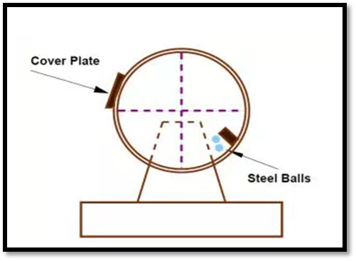
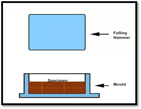

Fig.3: Flakiness and Elongation Test
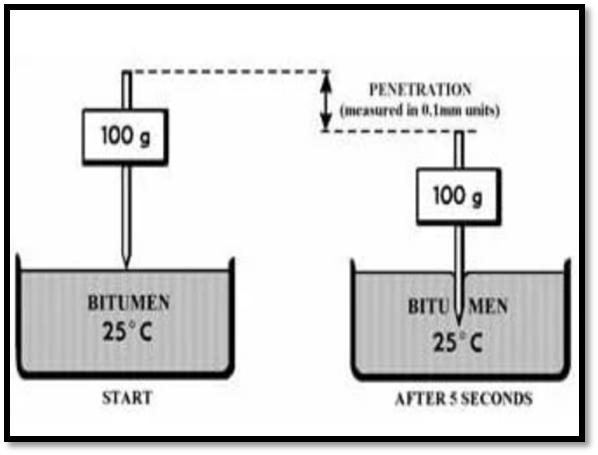
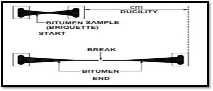
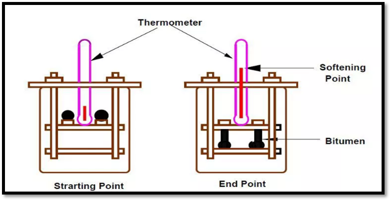
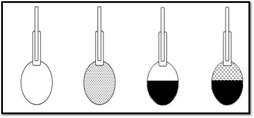
Fig.7: Pycnometer
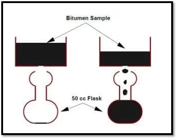
Fig.8: Viscosity Test
4.4.1 Types of Pavements
In addition to these, composite pavements are also available.
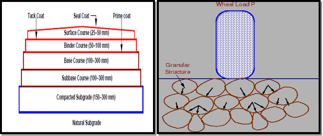 Fig.9: Flexible Pavement
A flexible pavement invariably consists of all the courses as shown in Fig 9. Thus, it is a multi-layered system with low flexural strength.
The external loads are largely transmitted to the subgrade through the intervening layers-the base and the sub-base – by means of interlocking at the grain-to-grain contacts in the granular structure.
Lateral distribution of the compressive stresses on to a larger area with increasing depth is the basic mechanism of stress transfer.
The thicknesses of the intervening courses are so designed as to keep the stresses transferred to the subgrade soil less than the allowable bearing pressure to ensure that deformations or settlements remain within permissible limits.
2. Types of Flexible Pavements
The following types of construction have been used in flexible pavement:
These are layered systems with high quality expensive materials are placed in the top where stresses are highand low quality cheap materials are placed in lower layers.
These are constructed by placing bituminous layers directly on the soil sub-grade. This is more suitable when there is high traffic and local materials are not available.
These are constructed by placing dense/open graded aggregate layers in between two asphalt layers.
Modified dense graded asphalt concrete is placed above the sub-grade will significantly reduce the vertical compressive strain on soil sub-grade and protect from surface water.
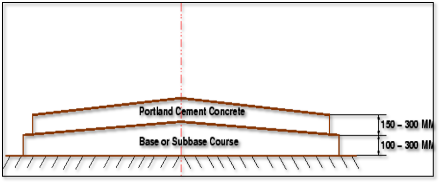
Fig.10: Typical Cross section of Rigid pavement |
Rigid pavements can be classified into four types:
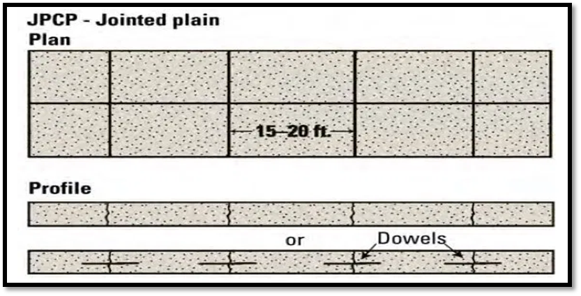
Fig.11: Jointed Plain Concrete Pavement
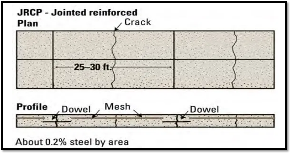
Fig.12: Jointed Reinforced Concrete Pavement
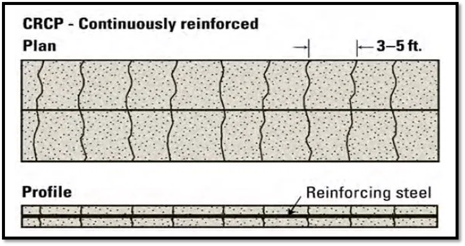
- CRCP designs have no transverse joints, but contain a significant amount of longitudinal reinforcement, typically 0.6 to 0.8 percent of the cross-sectional area.
- Transverse reinforcement is often used.
- The high content of reinforcement both influences the development of transverse cracks within an acceptable spacing (about 0.9 to 2.5 m apart) and serves to hold cracks tightly together.
Fig.13: Continuous Reinforced Concrete Pavement
5. Comparison between Flexible Pavements and Rigid Pavements
Sr. No. | Flexible Pavement | Rigid Pavement |
1. | It consists of a series of layers with the highest quality materials at or near the surface of pavement. | It consists of one layer Portland cement concrete slab or relatively high flexural strength. |
2. | It reflects the deformations of subgrade and subsequent layers on the surface. | It is able to bridge over localized failures and area of inadequate support. |
3. | Its stability depends upon the aggregate interlock, particle friction and cohesion. | Its structural strength is provided by the pavement slab itself by its beam action. |
4. | Pavement design is greatly influenced by the subgrade strength. | Flexural strength of concrete is a major factor for design. |
5. | It functions by a way of load distribution through the component layers | It distributes load over a wide area of subgrade because of its rigidity and high modulus of elasticity. |
6. | Temperature variations due to change in atmospheric conditions do not produce stresses in flexible pavements. | Temperature changes induce heavy stresses in rigid pavements. |
7. | Flexible pavements have self-healing properties due to heavier wheel loads are recoverable due to some extent. | Any excessive deformations occurring due to heavier wheel loads are not recoverable, i.e. settlements are permanent. |
Sr. No. | Flexible Pavement | Rigid Pavement |
8. | The earthen, gravel, water bound macadam and bituminous roads are known as flexible pavement. | Cement concrete roads are known as rigid pavement. |
9. | In flexible pavement, the top surface takes to shape of the sub surface soil. | The rigid pavement has more stiffness and capacity to bridge over loose soil pockets in the sub grade. |
10. | Due to more stiffness and thickness, there are no ups and downs on concrete roads. | Due to flexibility, there are ups and downs on WBM roads and bituminous roads, but there is no ups and down in case of rigid pavement. |
11. | Design principle based on load distribution characteristics of the components. | Designed and analyzed by using the elastic theory. |
12. | Granular material is used in flexible pavement. | Cement concrete either plain reinforced or pre stressed concrete is used in rigid pavement. |
13. | It has low or negligible flexural strength. | It is associated with rigidity or flexural strength or slab action so the load is distributed over a wide area of sub-grade soil. |
14. | Elastic deformation due to normal loading. | Acts as a beam or cantilever for normal loading. |
15. | Local depression due to excessive loading. | Causes cracks due to excessive loading. |
16. | Transmits vertical and compressive stresses to the lower layer. | Tensile stress and temperature stress increase. |
17. | It is constructed in the number of layers in design practice. | It is laid in slabs with steel reinforcement in design practice. |
18. | Road can be used for traffic within 24 hours. | Road cannot e used until 14 days of curing. |
19. | Rolling of the surfacing is required. | Rolling of the surfacing is not required. |
20. | Initial cost is low. | Initial cost is high. |
21. | Life span is short. | Life span is long. |
22. | Their thickness is more. | Their thickness is less. |
Key Takeaways:
4.4.2 Design factors
There are many factors that affect pavement design which can be classified into four categories as traffic and loading, structural models, material characterization, environment.
4.4.2.1 Traffic and loading
Traffic is the most important factor in the pavement design. The key factors include contact pressure, wheel load, axle configuration, moving loads, load, and load repetitions.
1. Contact pressure: The tyre pressure is an important factor, as it determines the contact area and the contact pressure between the wheel and the pavement surface. Even though the shape of the contact area is elliptical, for sake of simplicity in analysis, a circular area is often considered.
2. Wheel load: The next important factor is the wheel load which determines the depth of the pavement required to ensure that the Subgrade soil is not failed. Wheel configuration affects the stress distribution and deflection within a pavement. Many commercial vehicles have dual rear wheels which ensure that the contact pressure is within the limits. The normal practice is to convert dual wheel into an equivalent single wheel load so that the analysis is made simpler.
3. Axle configuration: The load carrying capacity of the commercial vehicle is further enhanced by the introduction of multiple axles.
4. Moving loads: The damage to the pavement is much higher if the vehicle is moving at creep speed. Many studies show that when the speed is increased from 2 km/hr to 24 km/hr, the stresses and deflection reduced by 40 per cent.
5. Repetition of Loads: The influences of traffic on pavement not only depend on the magnitude of the wheel load, but also on the frequency of the load applications. Each load application causes some deformation and the total deformation is the summation of all these. Although the pavement deformation due to single axle load is very small, the cumulative effect of number of load repetition is significant. Therefore, modern design is based on total number of standard axle load (usually 80 kN single axle).
6. Layered elastic model: A layered elastic model can compute stresses, strains, and deflections at any point in a pavement structure resulting from the application of a surface load.
7. Temperature: The effect of temperature on asphalt pavements is different from that of concrete pavements. Temperature affects the resilient modulus of asphalt layers, while it induces curling of concrete slab. In rigid pavements, due to difference in temperatures of top and bottom of slab, temperature stresses or frictional stresses are developed.
8. Precipitation: The precipitation from rain and snow affects the quantity of surface water infiltrating into the Subgrade and the depth of ground water table. Poor drainage may bring lack of shear strength, pumping, loss of support, etc.
Key Takeaways:
4.4.3 Design of bituminous paving mixes
A bituminous mix is defined as a mixture of coarse aggregates, fine aggregates, filler and binder in order to produce a mix with desirable properties like workability, strength, durability and economic considerations.
The objective of the mix design is to produce a bituminous mix with the following properties:
Three design methods for mix are available:
4.4.3.1 Constituents of a mix
4.4.3.2 Types of mix
4.4.3.3 Design of bituminous mixes
1. Selection of Aggregate
2. Determination of Specific Gravity
The average specific gravity Gm of the blended aggregate mix is calculated from the equation:
Gm = 
Here, W1, W2, W3, W4 are % by weight of aggregates and G1, G2, G3, G4 are their respective specific gravity.
3. Bulk specific gravity of mix Gm
The bulk specific gravity or the actual specific gravity of the mix Gm is the specific gravity considering air voids and is found out by:
Gm = 
Where, Wm is the weight of mix in air, Ww is the weight of mix in water, Note that gives the volume of the mix. Sometimes to get accurate bulk specific gravity, the specimen is coated with thin film of paraffin wax, when weight is taken in the water. This however requires considering the weight and volume of wax in the calculations.
Air voids Vv is the percent of air voids by volume in the specimen and is given by:
Vv =  X 100
X 100
Where, Gt is the theoretical specific gravity of the mix, and Gm is the bulk or actual specific gravity of the mix.
5. Percent volume of bitumen Vb
The volume of bitumen Vb is the percent of volume of bitumen to the total volume and given by:
Vb = 
Where, W1 is the weight of coarse aggregate in the total mix, W2 is the weight of fine aggregate in the total mix, W3 is the weight of filler in the total mix, Wb is the weight of bitumen in the total mix, Gb is the apparent specific gravity of bitumen, and Gm is the bulk specific gravity of mix.
6. Voids in mineral aggregate VMA
Voids in mineral aggregate VMA is the volume of voids in the aggregates, and is the sum of air voids and volume of bitumen, and is calculated from
Where, Vv is the percent air voids in the mix. And Vb is percent bitumen content in the mix.
7. Voids filled with bitumen VFB
Voids filled with bitumen VFB is the voids in the mineral aggregate frame work filled with the bitumen, and is calculated as:
VFB=
Where, Vb is percent bitumen content in the mix. And VMA is the percent voids in the mineral aggregate
4.4.3.4 Marshall Method of Bituminous Mix Design
Marshall Mix Design method involves selecting the bitumen binder content of a suitable density that satisfies minimum stability and range of flow values.
Marshall Stability of a test specimen is defined as the maximum load that produces failure when the specimen is pre-heated to a prescribed temperature and load is applied at a constant strain rate of 5 cm per minute. Simultaneously, a dial gauge is used to measure the vertical deformation of the specimen. Deformation value of 0.25 mm is called the Marshall Flow Value of the specimen.
Steps in Marshall Mix Design
Step 1: Determine the physical properties, size and gradation of aggregates.
Step 2: Select the type of asphalt/ bitumen binder.
Step 3: Prepare initial samples, each with different bitumen binder content.
Step 4: Average value of various properties are determined for each mix and the following graphical plots are prepared:
Step 5: Determine the optimum bitumen content for the mix design by taking average value of the following three bitumen contents found form the graphs obtained in the previous step:
Step 6: Compare each of these values against design requirements and if all comply with design requirements, then the selected bitumen content is acceptable. Otherwise, redesign the mixture.
Key Takeaways:
4.4.4 Design of Flexible Pavement by CBR method (IRC: 37- Latest revision)
4.4.4.1 California Bearing Ratio (C.B.R.) Test

4.4.4.2 Procedure of California Bearing Ratio Test
CBR (%) =  100
100
CBR(2.5mm) =  X 100
X 100
CBR(5.0mm) =  X 100
X 100
CBR = Higher of CBR2.5 mm/ CBR5.0 mm
Standard Load (2.5 mm Penetration) = 1370 Kg
Standard pressure/stress @ 2.5 mm = 
= 70 Kg/cm2
Standard pressure/stress @ 5.0 mm = 
= 105 Kg/cm2
CBR of a soil sample is average of CBR of three specimen prepared from same sample.
Generally, 2.5 mm CBR is more than 5 mm CBR. But if 5 mm CBR is more than 2.5 mm CBR, than test must be repReated again and again. If same result comes then higher value is considered as CBR i.e., CBR @ 5 mm.
Empirical formula for thickness, (T)cm= 
(Applicable for CBR>12%)
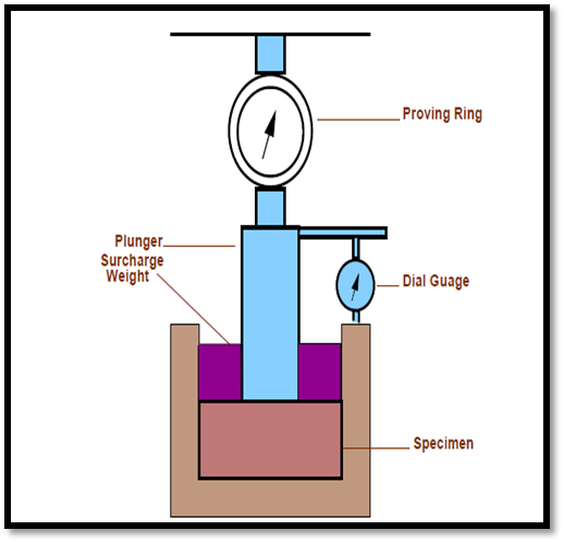
Fig.14: California Bearing Ratio Test
Key Takeaways:
4.4.5 Design of rigid pavement
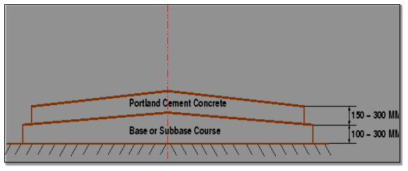
A rigid pavement, in contrast to a flexible one, derives its capacity to resist loads by virtue of its flexural strength.
Flexural strength allows the pavement to bridge over minor irregularities or weak spots in the subgrade or other courses such as the base or sub-base upon which it rests. Thus, the inherent strength of the pavement slab itself plays a major role in resisting the wheel loads; this, however, cannot under-rate the need for a strong subgrade.
It simply means that, provided a certain minimum support is derived from the subgrade, the performance of the rigid pavement is governed by the strength of the pavement slab rather than by that of the subgrade. Rigid pavements consist of cement concrete (OPC), which may be plain, reinforced or pre-stressed concrete.
The primary difference between a rigid pavement and a flexible one is in the structural behavior; the critical condition of stress is the maximum flexural stress in the pavement slab not only due to the wheel load, but also due to warping caused by changes in temperature in the summer and winter seasons, and during the day and night. The warping of the slab is caused by the temperature gradient between the top and bottom, and the consequent flexure.
Further, temperature changes tend to cause stresses due to friction at the interface between the slab and the layer below, which opposes the movement of the slab.
A rigid pavement can serve the dual purpose of a base and a wearing course. However, it is not normally laid directly over the subgrade when the latter consists of fine-grained soil.
Providing a base or a sub-base below the pavement can enhance the life of the pavement significantly, and may prove economical in the long run.
|
Fig.15: Typical Cross section of Rigid pavement |
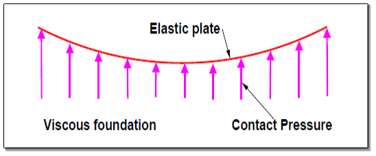
Fig.16: Stress Distribution
Key Takeaways:
4.4.6 Westergaard theory
The Westergaard method for rigid pavement design involves a calculation of the stresses acting in the pavement under the wheel load. This stress is then compared to the strength of the pavement slab to determine whether the slab is sufficiently strong to accommodate the proposed loadings.

Fig.17: Westergaard theory

Key Takeaways:
4.4.7 Load and temperature stresses
4.4.7.1 Temperature stresses
Temperature stresses are developed in cement concrete pavement due to variation in slab temperature. This is caused by (i) daily variation resulting in a temperature gradient across the thickness of the slab and (ii) seasonal variation resulting in overall change in the slab temperature. The former results in warping stresses and the later in friction stresses.
4.4.7.2 Warping stress
The warping stress at the interior, edge and corner regions, denoted as ti , te ,
te ,  tc in kg/cm2 respectively and given by the equation
St,i= 
St,e = Maximum of ( or
or 
St,c = 
 Coefficient of thermal expansion = 12 X 10-6/oC
t = temperature difference between top and bottom of the pavement.
a = radius of contact area
Cx & Cy = Coefficient which is based upon ,
,  ratio
ratio
Lx = Spacing between transverse joints
Ly = Spacing between longitudinal joints
4.4.7.3 Frictional stresses
The frictional stress of in kg/cm2 is given by the equation
 =
= 
Where, W is the unit weight of concrete in kg/cm2 (2400), f is the coefficient of sub grade friction (1.5) and L is the length of the slab in meters.
4.2.7.4 Combination of stresses
The cumulative effect of the different stress give rise to the following thee critical cases


Key Takeaways:
4.4.8 Joints
4.4.8.1 Expansion joints
The purpose of the expansion joint is to allow the expansion of the pavement due to rise in temperature with respect to construction temperature. The design consideration is:
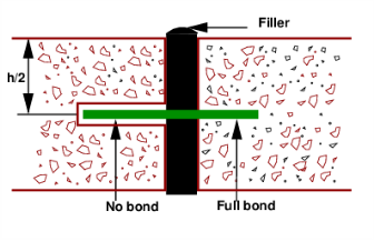
Fig.14: Expansion Joint
4.4.8.2 Contraction joints
The purpose of the contraction joint is to allow the contraction of the slab due to fall in slab temperature below the construction temperature. The design considerations are:
Lc = 
Where, Sc is the allowable stress in tension in cement concrete and is taken as 0.8 kg/cm2, W is the unit weight of the concrete which can be taken as 2400 kg/cm3 and f is the coefficient of sub-grade friction which can be taken as 1.5.

Fig.15: Contraction joint
4.4.8.3 Dowel bars
The purpose of the dowel bar is to effectively transfer the load between two concrete slabs and to keep the two slabs in same height. The dowel bars are provided in the direction of the traffic (longitudinal). The design considerations are:
1 Bradbury’s analysis
Bradbury’s analysis gives load transfer capacity of single dowel bar in shear, bending and bearing as follows:
Ps = 0.785 d2 Fs
Pf = 
Pb = 
Where, P is the load transfer capacity of a single dowel bar in shear s, bending f and bearing b, d is the diameter of the bar in cm, Ld is the length of the embedment of dowel bar in cm, δ is the joint width in cm, Fs, Ff, Fb are the permissible stress in shear, bending and bearing for the dowel bar in kg/cm2.
2 Design procedure
Step 1: Find the length of the dowel bar embedded in slab Ld by equating Eq. 12=Eq. 13, i.e.
Ld = 5d 
Step 2: Find the load transfer capacities Ps, Pf, and Pb of single dowel bar with the Ld
Step 3: Assume load capacity of dowel bar is 40 percent wheel load, find the load capacity factor f as
Max
Step 4: Spacing of the dowel bars.
4.4.8.4 Tie bars
In contrast to dowel bars, tie bars are not load transfer devices, but serve as a means to tie two slabs. Hence tie bars must be deformed or hooked and must be firmly anchored into the concrete to function properly. They are smaller than dowel bars and placed at large intervals. They are provided across longitudinal joints.
Step 1: Diameter and spacing: The diameter and the spacing is first found out by equating the total sub-grade friction to the total tensile stress for a unit length (one meter). Hence the area of steel per one meter in cm2 is given by:
As X Ss = b X h X W x f
As = 
Where, b is the width of the pavement panel in m, h is the depth of the pavement in cm, W is the unit weight of the concrete (assume 2400 kg∕cm2), f is the coefficient of friction (assume 1.5), and Ss is the allowable working tensile stress in steel (assume 1750 kg∕cm2). Assume 0.8 to 1.5 cm ϕ bars for the design.
Step 2: Length of the tie bar: Length of the tie bar is twice the length needed to develop bond stress equal to the working tensile stress and is given by:
Lt = 
Where, d is the diameter of the bar, Ss is the allowable tensile stress in kg∕cm2, and Sb is the allowable bond stress and can be assumed for plain and deformed bars respectively as 17.5 and 24.6 kg∕cm2.
Key Takeaways:
4.4.9 IRC method of rigid pavement design (IRC:58-2015)
A part of road section from Design Ch. 2+065 to Ch. 18+000 (L=16.935 km) is used by trucks carrying wet sand mined from nearby Betwa River. The water drips down from the trucks on the pavement surface all along the road way and has damaged the pavement in the form of stripping, cracking, potholes including base course failure. Rigid pavement is proposed in this length of 16.935km as dripping of water on concrete surface will not result in “stripping”.
In order to provide a stable construction platform and non-erodible support for PQC, a DLC sub base, 150mm thick, is included as part of the pavement structure. Similarly, a layer of relatively open graded GSB Gr-6 (as per IRC:58-2015 Table VI-I), 150mm thick above the sub grade has been considered for drainage of water to prevent excessive softening of sub grade and prevent erosion of the sub grade under adverse moisture condition.
A separation membrane of 125 micron polyethylene is considered to be placed between PQC and DLC to reduce inter-layer friction.
The dimensions of dowel bars & tie bars are given below:
Key Takeaways:
References:
1. L.R. Kadiyali, Transportation Engineering, Khanna Publishing House
2. Saxena, Subhash C, A Textbook of Highway and Traffic Engineering, CBS Publishers &
Distributers, New Delhi
3. Kumar, R Srinivasa, “A Text book of Highway Engineering”, Universities Press,
Hyderabad.
4. Kumar, R Srinivasa, “Pavement Design”, Universities Press, Hyderabad.
5. Chakraborty Partha & Das Animesh., “Principles of Transportation Engineering”,
Prentice Hall (India), New Delhi,
6. IRC : 37- Latest revision, “Tentative Guidelines for the design of Flexible Pavements”
Indian Roads Congress, New Delhi
7. IRC:58-2015 Guidelines for the Design of Plain Jointed Rigid Pavements for Highways
(Fourth Revision) (with CD)
8. IRC:65-2017 Guidelines for Planning and Design of Roundabouts (First Revision)
9. IRC:73-1980 Geometric Design Standards for Rural (Non-Urban) Highways
10. IRC:106-1990 Guidelines for Capacity of Urban Roads in Plain Areas
11. IRC:93-1985 Guidelines on Design and Installation of Road Traffic Signals.
12. IRC:92-2017 Guidelines for Design of Interchanges in Urban Areas (First Revision)
13. IRC: SP: 68-2005, “Guidelines for Construction of Roller Compacted Concrete Pavements”,
Indian Roads Congress, New Delhi.
14. IRC: 15-2002, “Standard Specifications and Code of Practice for construction of Concrete
Roads” Indian Roads Congress, New Delhi.
15. MORTH, “Specifications for Road and Bridge Works”, Ministry of Shipping, Road
Transport & Highways, Published by Indian Roads Congress, New Delhi.


