Unit – 1
DC Circuits
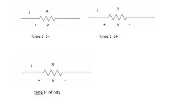
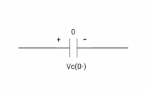
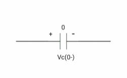
# In case of capacitor: - At time t= 0-
:. Capacitor is initially uncharged Q (0-) =0 Q=cv Q (0-) = cvc (0-) Vc (0-) =0 At time t= 0+
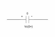
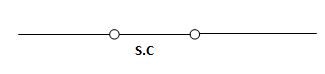
By low of conservation of charges Q (0-) = Q (0+) Cvc (0-) =cvc (0+) Vc (0+) =0 Hence acts as
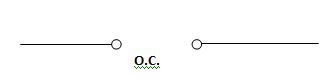
If capacitor is initially uncharged at t= 0- than voltage across capacitor is zero at t=0+ capacitorwill follow low of consvation of charges and Vc (0+) =0 it means at t=0+ capacitor behaves as short circuit in other words, voltage across capacitor cannot change instantaneously. At time t= infinity,
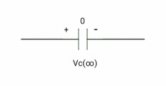
I = cdvc/dt constant and maximum hence, i= 0 At t= infinity capacitor will be fully charged or voltage across capacitor is constant and current through capacitor is zero so, capacitor will behave as open –circuit Say capacitor is initially charged
at time t= 0-,
at time t= 0+,
at time t= 0+
Q (0-) = Q (0+) Cvc (0-) =cvc (0+) V1 = Vc (0+)
Hence acts as
Its capacitor is initially charged at t= 0- as voltage across capacitor is V1 than at t=0+ capacitor behaves as a voltage as a voltage source with value V1 At time t = infinity
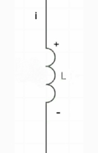
If capacitor is initially charged and it is connected to any independent source for long time than current through capacitor is 3 etw and capacitor will be fully charged and it behaves as o.c # for Inductor: - At time t= 0-
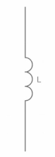
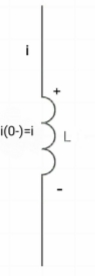
Ø= Li =0 Ø (0) = Li (0-) i (0-) =0 at t= 0+,
by low of conservation of flux Ø (0-) = Ø (0+) Li (0-) = Li (0+) 0 =i (0+) Hence, acts as short circuit
|


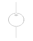
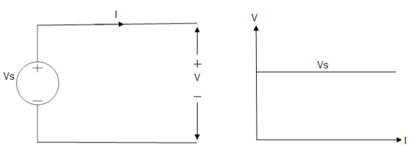
Ideal and practical Voltage and Current source: A voltage source is a device which provides a constant voltage to load at any instance of time and is independent of the current drawn from it. This type of source is known as an ideal voltage source. Practically, the ideal voltage source cannot be made. It has zero internal resistance. It is denoted by this symbol.
Fig: Voltage source symbol
Ideal Voltage Source
Fig: Ideal Voltage Source
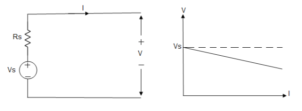
The graph represents the change in voltage of the voltage source with respect to time. It is constant at any instance of time. Voltage sources that have some amount of internal resistance are known as a practical voltage source. Due to this internal resistance, voltage drop takes place. If the internal resistance is high, less voltage will be provided to load and if the internal resistance is less, the voltage source will be closer to an ideal voltage source. A practical voltage source is thus denoted by a resistance in series which represents the internal resistance of source.
Practical Voltage source
Fig: Practical Voltage source
The graph represents the voltage of the voltage source with respect to time. It is not constant but it keeps on decreasing as the time passes.
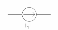
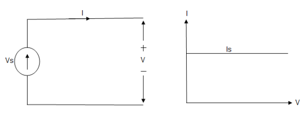
Current source A current source is a device which provides the constant current to load at any time and is independent of the voltage supplied to the circuit. This type of current is known as an ideal current source; practically ideal current source is also not available. It has infinite resistance. It is denoted by this symbol.
Ideal Current source
Fig: Ideal Current source
The graph represents the change in current of the current source with respect to time. It is constant at any instance of time.
Why ideal Current source has infinite resistance? A current source is used to power a load, so that load will turn on. We try to supply 100% of the power to load. For that, we connect some resistance to transfer 100% of power to load because the current always takes the path of least resistance. So, in order for current to go to the path of least resistance, we must connect resistance higher than load. This is why we have the ideal current source to have infinite internal resistance. This infinite resistance will not affect voltage sources in the circuit.
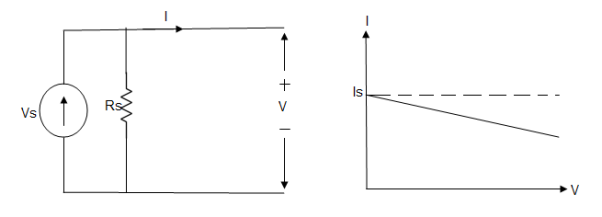
Practical Current source Practically current sources do not have infinite resistance across there but they have a finite internal resistance. So the current delivered by the practical current source is not constant and it is also dependent somewhat on the voltage across it. A practical current source is represented as an ideal current source connected with resistance in parallel.
Fig; Practical Current source
The graph represents the current of the current source with respect to time. It is not constant but it also keeps on decreasing as the time passes.
Examples of current and voltage sources The examples of current source are solar cells, transistors and examples of some voltage sources are batteries and alternators.
This was all about ideal and practical sources of power. The ideal sources are very useful for calculations in theory but as ideal sources are not practically possible, only practical sources are used in practical circuits. The batteries we use are a practical source of power and the voltage and current decreases as we use it. Thus both are useful to us in their own ways.
|

Linearity is the behaviour of the circuit for example an amplifier in which the output signal strength varies in direct proportion to the input signal strength.
In a linear device the output to input signal amplitude ratio is the same no matter what the strength of the input signal
In amplifier the output-versus-input signal amplitude graph appears straight line.
|
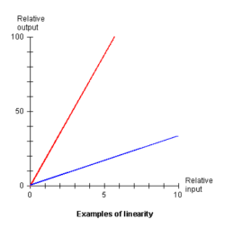
The gain or amplification factor determines the slope of the line. The steeper the slope the greater the gain. The amplifier depicted in red lines has more gain than one depicted by blue line.
Linear network:
In simple words, a linear circuit is an electric circuit in which circuit parameters Resistance, inductance, capacitance, waveform, frequency etc are constant. In other words, a circuit whose parameters are not changed with respect to Current and Voltage is called Linear Circuit.
Linear literally means along with a straight line. The linear characteristics in between current and voltage means current flowing through a circuit is directly proportional to the applied Voltage.
If we increase the applied voltage, then the current flowing through the circuit will also increase, and vice versa. If we draw the circuit output characteristic curve in between current and voltage, it will look like a straight line.
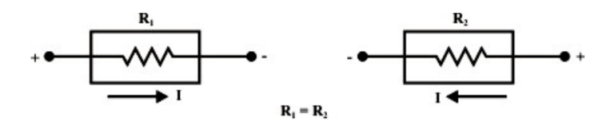
The conduction of current in both directions in an element example Resistance Inductance and Capacitance with same magnitude are termed as Bilateral element.
|
Unilateral element:
The conduction of current in one direction is termed as unilateral element. Example:
Diode, Transistor.
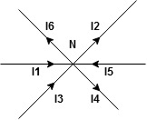
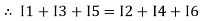
The algebraic sum of currents meeting at a junction or node in a electric circuit is zero or the summation of all incoming current is always equal to summation of all outgoing current in an electrical network. Explanation
Assuming the incoming current to be positive and outgoing current negative we have
I e
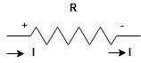
Kirchhoff’s Voltage Law (KVL) statement : the algebraic summation of all Voltage in any closed circuit or mesh of loop zero. ie ∑ Voltage in closed loop = 0 the summation of the Voltage rise (voltage sources) is equal to summation of the voltage drops around a closed loop in 0 circuit for explanation from here determination of sigh and direction of currents (Don’t write in exams just for understanding)
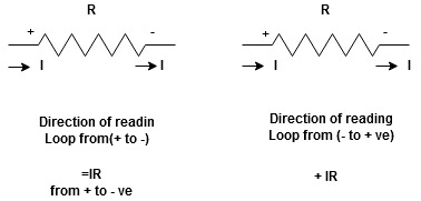
current entering a resistor is +ve and leaving should be –ve now
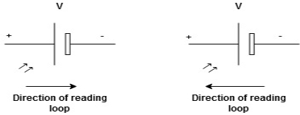
Potential Rise Potential Drop
We are reading from +V to –V we are reading from –V to +V
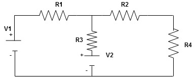
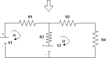
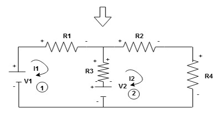
Given Circuit
First identify no of loops and assign direction of current flowing in loop Note : no of loops in circuit = No, of unknown currents = no, of equations in the circuit
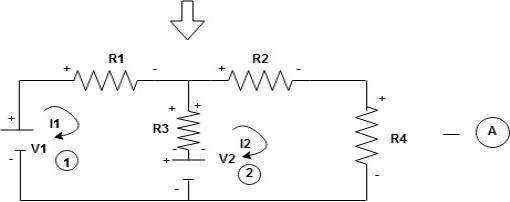
Note : keep loop direction and current direction same ie either clockwise or anticlockwise for all loops I1 I2 Now according to direction of direction assign signs (+ve to –ve) to the resistors
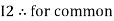
Note : voltage sources (V) polarities does not change is constant. Note: for common resistor between 2 loops appearing in the circuit like R3 give signs according to separate loops as shown
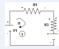
When considering only loop no 1 (+ R3 - )
- B
Now consider diagram A and write equations Two loops
Apply KVL for loop ① [B. Diagram ] (+ to drop -) = - sign and (- to rise +) = + sign
- -(
Similarly for loop no. 2 currents flowing is
Consider loop no. 1 apply KVL - - Consider loop no. 2 apply KVL - - After solving equation ① and ② we will get branch current |


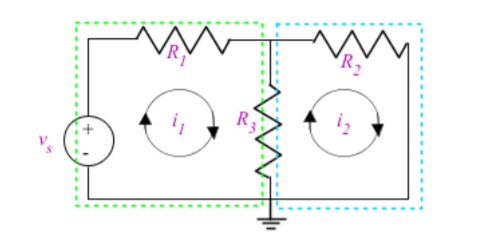
In loop analysis we use mesh which is a loop that does not have any other loops inside it. A mesh starts at a node and traces a path around a circuit, returning to the original node without hitting any nodes more than once. To obtain the mesh equations to be able to interpret the circuit. The mesh equations are obtained by 1. Applying Kirchhoff's voltage law (KVL) to each mesh in the circuit. 2. Express the voltages of elements in terms of the mesh currents.
The circuit has 2 meshes in it outlined in green and blue dotted lines. The currents i1 and i2 are the currents around a mesh. The method behind mesh analysis is to examine the mesh in terms of the voltages of each element and express that with mesh currents. Using Ohm's law, we can express the voltage across R1 as R1.i1
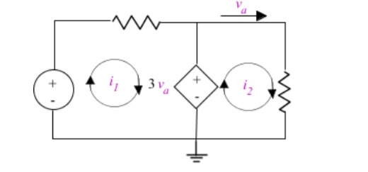
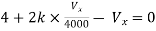
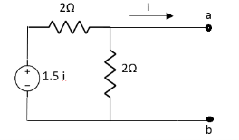
Use this approach across a circuit applying KVL to find the mesh equations, then use these equations to solve for unknown current. In case where a dependent source is present in a circuit, the controlled current or voltage of that source must also be expressed by the mesh currents. Examine the circuit and find which part of the circuit controls the dependent source and express that voltage or current with the mesh currents that affect it.
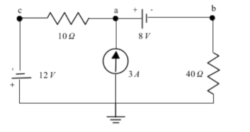
In this circuit, a dependent source generates voltage depending on the current at va. To express this in terms of the mesh currents examine the circuit which shows that the current is equal to the mesh current. Therefore, the dependent source will force volts into the system, and now mesh analysis can be performed to solve for the remaining unknowns. Nodal Analysis: We use nodal analysis on circuits to obtain KCL equations used to solve for voltage and current in a circuit. The number of KCL equations is one less than the number of nodes that a circuit has. The extra node may be referred as reference node. If a circuit contains ground which ever node the ground is connected to is selected as the reference node. This is used to find the voltage differences at each other node in the circuit with respect to the reference.
Ideally, we set the voltage to 0 V at the reference node to simplify calculations, however it can be set to any value if the other nodes account for the different reference voltage. Solving the node equations can provide us with the node voltages. The node equations are obtained by completing two things: 1. Express the current through an element in terms of the node voltages. 2. Apart from the reference node, apply KCL to each other node in the circuit.
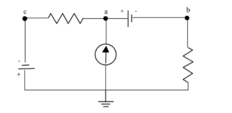
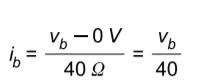
Here, node c is an example of a super node which is a connection between two nodes via an independent or dependant voltage source. Because super nodes are connected to a voltage source we can find their voltage immediately. In this case the voltage across the source will be 12 =0-vc = -12V . Similarly node A is related to node b as super node va = vb + 8V. We can substitute va and vc into our KCL equations to solve for vb. Calculate KCL equations at node a in figure 3. The current source is directing current into node a . Assume the current flows away from a towards node b and c. The KCL equation for node a is [A] = ib + ic The current across the resistor represented by the node voltages is found through Ohm's law as the potential across the element divided by the resistance. Note the assumed direction of the current to ensure the correct polarity of the difference in potential.
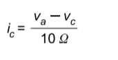
The current through node c will be equivalent to the potential across the resistor10 Ω divided by the resistance.
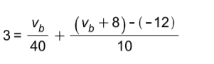
Substituting in the currents and and using the equations for and , the KCL equation at node A is found to be
Solving we get va =16V and vb =8V . |
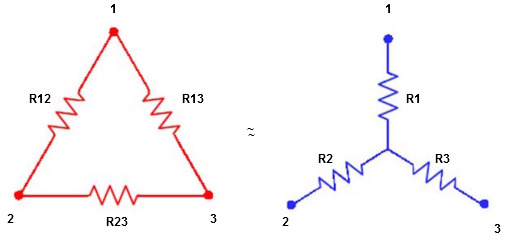
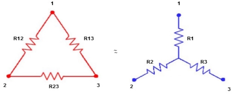
Star to delta conversion to final equivalent resistance
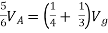
We know that (from delta to star conversion) R1 =
R2 =
R1 =
Multiply ① X ② L.H.S and R.H.S
R1 R2 =
Similarly multiply ② X ③
R2 R3 =
And ③ X①
R1 R3 =
Now add equation ④, ⑤, and ⑥ L.H.S and R.H.S
(Delta) Similarly R23 = R2+R3 +
R23 = R1+R2 +
Delta = R12// (R23 + R13) =R1 + R2
=
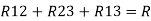
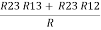
= Here let R = R12 + R23 + R13
=
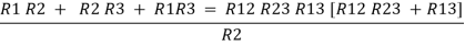
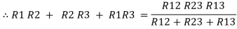
Now the 3 equations after equating L.H.S. and R.H.S R1 + R2 =
R2 + R3 =
R1 + R3 =
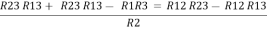
Now subtract ② and ① on L.H.S. and R.H.S
R2+ R3 – R1 – R2 =
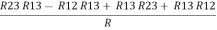
Now add equation ④ and ③
R3 – R1 + R1 + R3 =
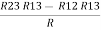
2R3 =
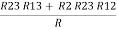
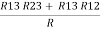
Similarly R1 =
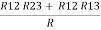
And R2 = R23 R12/R where R = R12 + R23 + R13 ie star equivalent from delta network is ratio of product of adjacent branches in delta to the addition of all branches in delta.
|


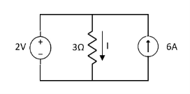
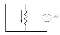
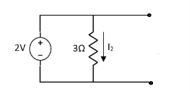
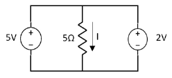
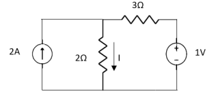
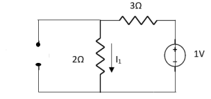
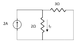
This is only applicable to circuits with linear elements. If two or more than two independent sources (voltage or current) are operating in the circuit than voltage across any element or current through any element is sum of current and voltages due to individual sources. Question 1. Find the current through
Solution:
Special Case:
Since two voltage sources with different magnitude in parallel which cannot be connected as in single branch two different current is not possible (if 5V than I = zero).
Question:
=
= |


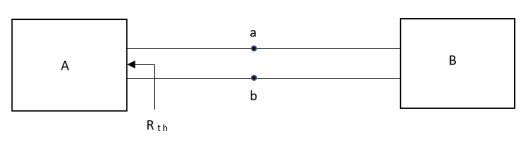
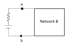
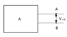
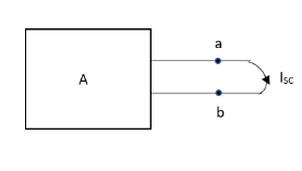
Thevenin’s equivalent of A
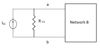
Norton’s equivalent of A
CONDITIONS FOR APPLICATION
Firstly, open circuit terminal A and B.
2. If network A is operating with independent and dependent sources:
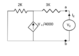
3. If network is operating with only dependent sources: Connect generation between A and B
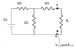
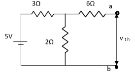
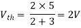
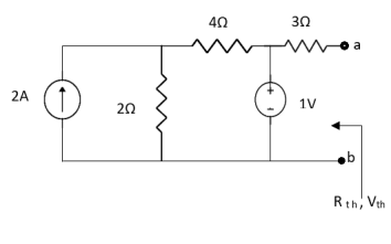
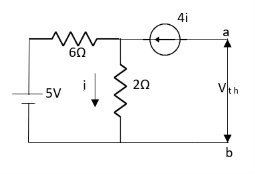
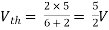
First open circuit terminal A and B. Find out the voltage between A and B this is Vth
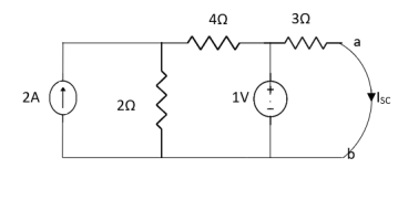
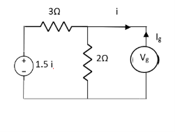
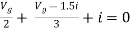
Question:
Answer:
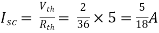
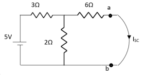
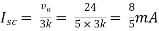
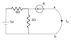
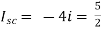
Finding Isc from circuit directly:
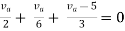
By KCL,
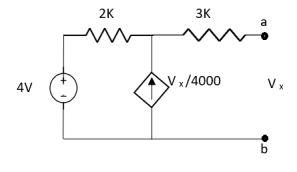
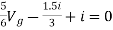
Question: Answer
Also, clear from circuit that Vth = 1V.
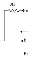
By applying KVL we get, 1-3Isc=0 Isc= Que:
Ans;
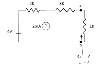
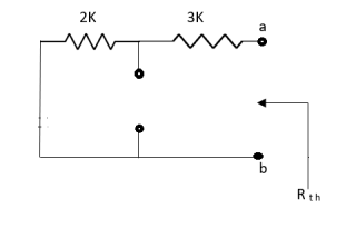
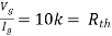
Rth=3k+2k=5k By applying KVL we get Therefore, Question:
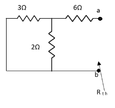
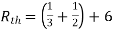
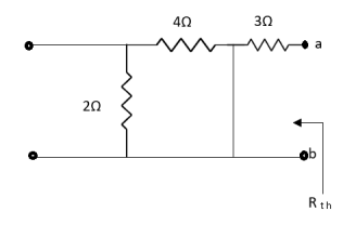
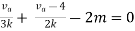
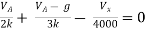
Solution: For Rth
By KCL, But,
By KVL,
Question:
Solution: Since, no independent source is present so, Isc = 0 And we know that,
Since Rth cannot be zero
But
|


Question: Find out the Norton’s equivalent
Solution:
Since, there is no significance of current source
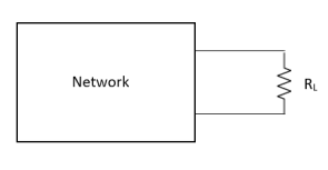
Maximum Power Transfer Theorem
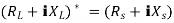
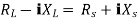
Where Rth is Thevenin’s equivalent resistance across a and b.
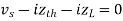
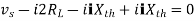
Maximum power is absorbed by ZL when Condition: Comparing real and imaginary parts OR Maximum power absorbed by ZL is
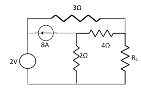
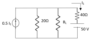
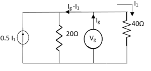
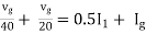
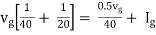
Question: Find out the value of load resistance if power absorbed is maximum.
Solution: find Thevenin’s equation
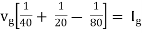
Question: Find maximum power delivered is RLif its value is
Solution
Therefore,
|


Reference Books
1. E. Hughes, “Electrical and Electronics Technology”, Pearson, 2010.
2. L. S. Bobrow, “Fundamentals of Electrical Engineering”, Oxford University Press.
3. V. D. Toro, “Electrical Engineering Fundamentals”, Pearson India.


