Unit - 5
Introduction to Mechatronics
Introduction
Mechatronics is a multidisciplinary branch of engineering that focuses on the engineering of both electrical and mechanical systems and also includes a combination of robotics, electronics, computer, telecommunications systems and product engineering. Originally, the field of mechatronics was intended to be nothing more than a combination of mechanics and electronics, hence the name being a portmanteau of mechanics and electronics; however, as the complexity of technical systems continued to evolve, the definition had been broadened to include more technical areas.
Advantages of Mechatronics
• It is cost effective and it can produce high quality products.
• It serves effectively for high dimensional accuracy requirements.
• It provides high degree of flexibility to modify or redesign the systems.
• It provides excellent performance characteristics.
• It Results in automation in production, assembly and quality control.
• Mechatronic systems provide the increased productivity in manufacturing organization.
• It has greater extend of machine utilization.
• Higher life is expected by proper maintenance and timely diagnosis of the fault.
Disadvantages of Mechatronics
• The initial cost is high.
• Maintenance and repair may workout costly.
• Multi-disciplinary engineering background is required to design and implementation.
• It needs highly trained workers to operate.
• Techno-economic estimation has to be done carefully in the selection of mechatronic system.
• It has complexity in identification and correction of problems in the systems.
Mechatronics is widely used in your day-to-day life.
It is used in appliances like washing machines and dishwashers.
It's also used in measuring devices like testing of sensors, and calibration devices.
Moreover, its uses in automatic air conditioning systems, automatic door systems, and security systems improve the quality of life as well as the security of secure facilities.
Furthermore, it's used in unmanned aerial vehicles as well as automatic guided vehicles for mine detection. Mechatronics technology use cuts across industries and is useful to just about everyone.
The objective of Automobile Engineering (Autotronics) is to develop and understand the principles of conversion in design, construction and working of mechanical systems and electronic systems in automobiles. The aim is to produce graduates with a broad understanding of all contextualized elements related to the electronic environment. Graduates will be equipped to solve multi-disciplinary problems and will be part of future developments in industries. It is anticipated that graduates from the course will play a major/lead role in design, management and coordination of multi-disciplinary projects.
Application
he main areas of automobiles using autotronics are engine controlling system, airbags, antilock braking system, lightening interiors, GPS, music systems etc.
Bionics
The abilities of humans provide both a goal and inspiration, for the development of robotic systems. We try to understand these abilities to meld them into technical systems and to assist the human in various settings.
In order to understand the human “model”, we acquire bio-data like muscle activity, exerted forces, and performed motions by recording different measures, e.g., electromyography (EMG) and ultrasound. This data can expose very different sets of information, including the behavior of the subject, his intentions, or abilities. Our goal is to process the data in a manner that lets us extract the information of interest. Once the information is extracted we can use it for different purpose.
Avionics
are the electronic systems used on aircraft, artificial satellites, and spacecraft. Avionic systems include communications, navigation, the display and management of multiple systems, and the hundreds of systems that are fitted to aircraft to perform individual functions. These can be as simple as a searchlight for a police helicopter or as complicated as the tactical system for an airborne early warning platform.
The term avionics is a portmanteau of the word’s aviation and electronics
In simple terms, a sensor is a device that detects changes and events in a physical stimulus and provides a corresponding output signal that can be measured and/or recorded. Here, the output signal can be any measurable signal and is generally an electrical quantity.
Sensors are devices that perform input function in a system as they ‘sense’ the changes in a quantity. The best example of a sensor is mercury thermometer. Here the quantity that is being measured is heat or temperature. The measured temperature is converted to a readable value on the calibrated glass tube, based on the expansion and contraction of liquid mercury.
Actuators are devices that work opposite to sensors. A sensor converts a physical event into an electrical signal, whereas an actuator converts electrical signal into a physical event. When sensors are used at input of a system, actuators are used to perform output function in a system as they control an external device.
Transducer
Transducers are the devices that convert energy in one form into another form. Generally, the energy is in the form of a signal. Transducer is a term collectively used for both sensors and actuators.
The basic requirements of a sensor are:
Classification of Sensors
The scheme of classifying sensors can range from very simple to very complex. The stimulus that is being sensed is an important factor in this classification.
Some of the stimuli are
The sensors’ conversion phenomenon is also an important factor in classification of sensors. Some of the conversion phenomena are magneto electric, thermoelectric and photoelectric.
Based on the applications of sensors, their classification can be made as follows.
I. Displacement, Position and Proximity Sensors
II. Temperature Sensors
III. Light Sensors
IV. Velocity and Motion
V. Fluid Pressure
VI. Liquid Flow and Level
VII. IR Sensor
VIII. Force
IX. Touch Sensors
X. UV Sensors
All the sensors can be classified into two types based on the power or signal requirement. They are Active sensors and passive sensors.
A Simple System using Transducers
A public addressing system is an example of a system using sensors and actuators.

It consists of a microphone, an amplifier and a loudspeaker. The sensor or the device with input function is a microphone. It senses the sound signals and transforms them into electrical signals. The amplifier receives these electrical signals and amplifies their strength.
The actuator or the device with output function is loudspeaker. It receives the amplified electrical signals from the amplifier and converts them back into sound signals but with more reach.
Kinematic chain: It is a linkage of elements and joints that transmit a controlled output motion related to a given input motion.
Kinematic Pair is the combination of the links or the machine elements. Likewise, the Kinematic Chain is also the combination of the Kinematic pairs.
The most important kinematic chains are those with four lower pairs. A lower pair is called when the pair is sliding or turning or screw pair.
Four Bar Chain or Four Bar Mechanism
Four Bar chain is also is known as the Quadric Cycle chain. The four Bar chain will have four links, each of these links will form one turning pair. These four links can be of different lengths.
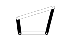
Four Bar Mechanism
According to Grashof’s law for a Four bar mechanism, the sum of the shortest and the longest link lengths should be greater than the sum of the other two links.
One of the most important considerations for any mechanism is that one of the links should complete one complete revolution. Which will be the input crank for the mechanism.
In this Four bar mechanism as shown in the above gif image, It converts the rotary motion into the oscillating motion.
Single Slider Crank Chain
The Single Slider Crank Chain mechanism is nothing but the modified Four Bar mechanism. Unlike all the four turning pairs in the four-bar mechanism, The Single slider crank chain mechanism will consist of the three turning pairs and one sliding pair.
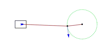
Single Slider Crank Chain Mechanism
As you can see the 1. crank, 2. connecting link 3. fixed base as the fixed link 4. position moving in the crosshead are the four links. and the piston and the crosshead are making the sliding pair and the rest are making the turning pairs.
All the reciprocating Engines will be running on this mechanism only. This mechanism will convert the reciprocating motion into the rotary motion as well as the vice versa.
Double Slider Crank Chain
The name itself represent that it will have two sliding pairs and two turning pairs in the double slider crank chain mechanism.
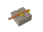
Double Slider Crank Chain
As you can see the above picture which is an example for the Double slider crank chain mechanism. In that, we have four elements (two sliding elements, one lever, slotted one base).
The two sliding elements joined by the lever element. This liver will be making two turning pairs with the two sliding elements. The slotted base which will make the two sliding pairs with the sliding elements.
What is Cam?
When the two links are connected either along a line or at a point, it is called a higher pair. Two such higher pair mechanisms will be included in a cam-follower system. A higher pair mechanism is known as cam and follower.
For the smooth functioning of a cam-follower mechanism, it is imperative that the follower should move smoothly without requiring too much input power, which means the follower should not jam, during its movement.
In an IC engine the valves have to be kept open; first, then close it and keep it closed, all these timing operations can be easily set by having cam-follower mechanisms. In the case of linkages, we study about planar linkages or two- dimensional linkages and more.
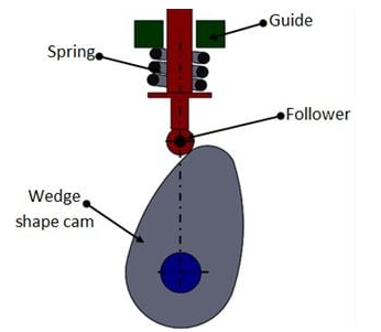
Types of CAM:
The following five types of CAM:
Disc or Plate Cam
Cylindrical Cam
Translating Cam
Radial Cam
Wedge Cam
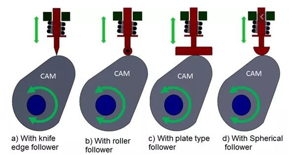
Disc or Plate Cam:
A disc or plate cam is a type of cams in which follower moves radially from the center of rotation of the cam. These cams are very popular due to their simple design and compactness that can be fitted into remote places. The application of Disc or Plate Cam is in I.C engines and machine tools.
Cylindrical Cam:
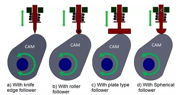
A Cylindrical cam is the cam in which the cylinder rotates about its axis has a circumferential contour cut on the cylinder surface. They are also of two types in the first types a groove is cut on the surface of the cam and the roller and has a positive oscillating motion. Another one is having a cylinder as the working surface. In this type of cam spring-loaded follower translates along the parallel axis to the rotating cylinder.
Translating Cam:
Translating cam is the type of cam in which cam can move in a horizontal plane. The follower attached too, it has the motion constrained with the help of the spring. Sometimes groove cams are used in which the follower motion is achieved without the use of the spring.
Radial Cam:
If the input link also called cam rotates as angular motion, then cam has rotational or angular motion and then we call it a radial cam.
This profiled body is called the cam. This has a revolute pair with the fixed link that is the foundation or fixed link. Cam is the revoluting link. There is a revolute pair between fixed link and the cam and the output link is the follower. If this cam rotates depending on the profile or shape of the cam, the follower will have translatory motion along with this prismatic pair between fixed link and the follower.
Wedge Cam:
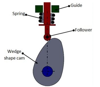
If the cam has a linear motion, then we call it a wedge cam. Wedge cam has a four-link mechanism, first is the fixed link, the cam which looks like a wedge is the other link. It depends on the profile of this wedge, as this cam oscillates in the horizontal direction, the follower will oscillate along the vertical direction along with this prismatic pair or this guide.
A toothed mechanism for the conversion of reciprocating rotary motion into intermittent rotary motion in one direction.
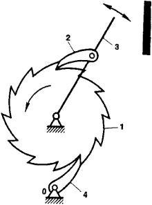
As shown in Figure 1, a ratchet mechanism consists of a ratchet wheel (1), a driving pawl (2), an arm (3), a locking pawl (4), and a support (0). The driving pawl engages the teeth of the ratchet wheel under the action of a spring or of its own weight. When the arm moves counterclockwise, the driving pawl turns the ratchet wheel through a certain angle. When the arm moves clockwise, the catch slips past one or more teeth, but the locking pawl prevents the clockwise rotation of the ratchet wheel.
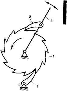
Figure. Diagram of a ratchet mechanism
Ratchet mechanisms are used in, for example, bicycles and machine tools. In loadlifting machines, ratchet mechanisms prevent the drum of the winch from moving backward under the weight of the load.
What is a gear?
A gear is a kind of machine element in which teeth are cut around cylindrical or cone shaped surfaces with equal spacing. By meshing a pair of these elements, they are used to transmit rotations and forces from the driving shaft to the driven shaft. Gears can be classified by shape as involute, cycloidal and trochoidal gears. Also, they can be classified by shaft positions as parallel shaft gears, intersecting shaft gears, and non-parallel and non-intersecting shaft gears
Spur Gear
Gears having cylindrical pitch surfaces are called cylindrical gears. Spur gears belong to the parallel shaft gear group and are cylindrical gears with a tooth line which is straight and parallel to the shaft. Spur gears are the most widely used gears that can achieve high accuracy with relatively easy production processes. They have the characteristic of having no load in the axial direction (thrust load). The larger of the meshing pair is called the gear and smaller is called the pinion.
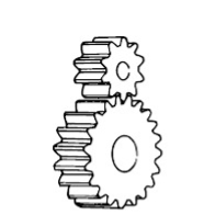
A sketch of spur gears
Helical Gear
Helical gears are used with parallel shafts similar to spur gears and are cylindrical gears with winding tooth lines. They have better teeth meshing than spur gears and have superior quietness and can transmit higher loads, making them suitable for high speed applications. When using helical gears, they create thrust force in the axial direction, necessitating the use of thrust bearings. Helical gears come with right hand and left hand twist requiring opposite hand gears for a meshing pair.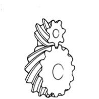
A sketch of helical gears
Gear Rack
Same sized and shaped teeth cut at equal distances along a flat surface or a straight rod is called a gear rack. A gear rack is a cylindrical gear with the radius of the pitch cylinder being infinite. By meshing with a cylindrical gear pinion, it converts rotational motion into linear motion. Gear racks can be broadly divided into straight tooth racks and helical tooth racks, but both have straight tooth lines. By machining the ends of gear racks, it is possible to connect gear racks end to end.
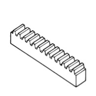
A sketch of gear rack
Bevel Gear
Bevel gears have a cone shaped appearance and are used to transmit force between two shafts which intersect at one point (intersecting shafts). A bevel gear has a cone as its pitch surface and its teeth are cut along the cone. Kinds of bevel gears include straight bevel gears, helical bevel gears, spiral bevel gears, miter gears, angular bevel gears, crown gears, zerol bevel gears and hypoid gears.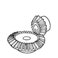
A sketch of bevel gears
Spiral Bevel Gear
Spiral bevel gears are bevel gears with curved tooth lines. Due to higher tooth contact ratio, they are superior to straight bevel gears in efficiency, strength, vibration and noise. On the other hand, they are more difficult to produce. Also, because the teeth are curved, they cause thrust forces in the axial direction. Within the spiral bevel gears, the one with the zero twisting angle is called zerol bevel gear.
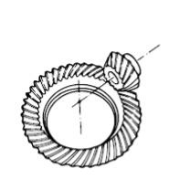
A sketch of spiral bevel gears
Screw Gear
Screw gears are a pair of same hand helical gears with the twist angle of 45° on non-parallel, non-intersecting shafts. Because the tooth contact is a point, their load carrying capacity is low and they are not suitable for large power transmission. Since power is transmitted by the sliding of the tooth surfaces, it is necessary to pay attention to lubrication when using screw gears. There are no restrictions as far as the combinations of number of teeth.
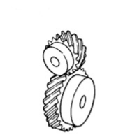
A sketch of screw gears
Miter Gear
Miter gears are bevel gears with a speed ratio of 1. They are used to change the direction of power transmission without changing speed. There are straight miter and spiral miter gears. When using the spiral miter gears it becomes necessary to consider using thrust bearings since they produce thrust force in the axial direction. Besides the usual miter gears with 90° shaft angles, miter gears with any other shaft angles are called angular miter gears.
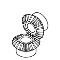
A sketch of miter gears
Worm Gear
A screw shape cut on a shaft is the worm, the mating gear is the worm wheel, and together on non-intersecting shafts is called a worm gear. Worms and worm wheels are not limited to cylindrical shapes. There is the hour-glass type which can increase the contact ratio, but production becomes more difficult. Due to the sliding contact of the gear surfaces, it is necessary to reduce friction. For this reason, generally a hard material is used for the worm, and a soft material is used for worm wheel. Even though the efficiency is low due to the sliding contact, the rotation is smooth and quiet. When the lead angle of the worm is small, it creates a self-locking feature.
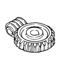
A sketch of worm gears
Internal gear
Internal gears have teeth cut on the inside of cylinders or cones and are paired with external gears. The main use of internal gears are for planetary gear drives and gear type shaft couplings. There are limitations in the number of teeth differences between internal and external gears due to involute interference, trochoid interference and trimming problems. The rotational directions of the internal and external gears in mesh are the same while they are opposite when two external gears are in mesh.
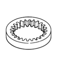
A sketch of internal gear
Power transmission by belt drive is one of the most common and universally used methods of transmission system when two shafts are parallel (up to 10 m) to each other as shown in Fig. A belt drive consists of two parallel shafts and a pulley is mounted on each shaft.
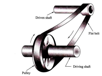
An endless belt runs over the surface of the pulley. There may be slippage between them and hence it cannot be called as a positive drive. When the belt runs over the pulley, there is always a friction which acts in between the pulley surface and the belt surface in the opposite direction of motion. The belt transmits power by friction only. The belt drive system can be used for long center-to-center distance of the shaft. For effective transmission, friction between the pulley surface and the belt surface should be as high as possible.
As it is well known, in most of the systems friction is not a desirable phenomenon and should be as minimum as possible.
1. Flat Belt Drive:
A belt is a thin band made of leather, synthetic rubber, canvas, or thread embedded in rubber or balata. These belts are made flat and rectangular in cross section. The belts are made endless by joining the two ends of the belt by pins or stitching as shown in Fig.
The system may be applicable for individual drive or group drive. Individual belt drive can be used when each machine will have its own electric motor. In case of group drive, a high-capacity motor drives an overhead shaft called main shaft or live shaft and the main shaft drives another shaft called counter shaft which drives another machine shaft.
The rotational power from driving pulley to the driven pulley is transmitted due to friction between the belt surface and the pulley surface. The belt will have two sides, one side will be in tension called tension side where as the other side will be in lesser tension called slack side as shown in Fig. 9.3.
The tension side (T1) and the slack side (T2) of the belt depend on the direction of rotation of the driving pulley.
Advantages:
i. Simple method, universally used arrangement, operation is smooth if the belt is of proper size.
ii. Low maintenance cost and long life.
iii. Flexibility is more.
iv. The level of shock is less.
v. Suitable for two parallel shafts.
vi. Suitable for long distances between two center-to-center shafts.
Disadvantages:
Endless belt is made by joining the two ends by pins. The belt tends to get damaged near the joints which reduces its life. This may require periodic replacement of the belt.
ii. The system is not suitable for short-distance shaft.
iii. Efficiency is found less due to slippage and creep, if the size of the belt is not proper.
iv. The system is not a positive drive.
Flat belt arrangement may be of two types:
(a) Open flat belt drive and
(b) Cross flat belt drive.
(a) Open Flat Belt Drive:
Figure 9.3 shows an open flat belt drive arrangement. There are two pulleys mounted on two parallel shafts. A flat belt runs over the pulley straight. The belt keeps running in the same direction. This arrangement is most suitable when the center-to-center distance of the two shafts is large and both sides of the belt are parallel to each other. Pulley A is driver pulley and B is driven pulley and the rotation of both A and B is clockwise. The lower portion of the belt is the tight side with tension T1 and the upper side of the belt is the slack side with tension T2 such that T1 > T2.
(b) Cross Flat Belt Arrangement:
The arrangement of a cross flat belt arrangement is shown in Fig. 9.4. It is used when two shafts are parallel to each other but they are to be rotated in opposite direction. Driving pulley shaft A is rotated in clockwise direction whereas driven pulley shaft B is rotated in anti-clockwise direction. The two-shaft center-to-center distance is L.
In this driving system, there is a junction point where belts are crossing each other and they will have wear and tear due to constant rubbing effect during operation. This effect is continuous. However, the rubbing effects can be avoided by increasing the center-to-center distance equal to 20 times the width of the belt. Such system is found suitable when the system is operated at low velocity.
Bearings are "parts that assist objects' rotation". They support the shaft that rotates inside the machinery.
Machines that use bearings include automobiles, airplanes, electric generators and so on. They are even used in household appliances that we all use every day, such as refrigerators, vacuum cleaners and air-conditioners.
Bearings support the rotating shafts of the wheels, gears, turbines, rotors, etc. in those machines, allowing them to rotate more smoothly.
In this way, all sorts of machines require a great many shafts for rotation, which means bearings are almost always used, to the point where they have become known as "the bread and butter of the machine industry". At first glance, bearings may seem like simple mechanical parts, but we could not survive without bearings.
Function
Friction is bound to occur between the rotating shaft and the part that supports the rotation. Bearings are used between these two components.
The bearings serve to reduce friction and allow for smoother rotation. This cuts down on the amount of energy consumption. This is the single most important function of bearings.
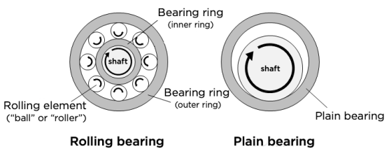
Fig: The structures of a rolling bearing and a plain bearing
The "rolling bearing", with its rolling motion, reduces friction more than the "plain bearing" with its sliding motion, allowing for a greater decrease in the amount of energy consumption during rotation.
Pneumatic deals with air pressure
Hydraulic deals with fluid motion and pressure

What Is a Pneumatic Actuation System?
Pneumatic actuators are highly reliable, efficient and safe sources of motion control that use pressurized air or gas to convert energy into rotary or linear motion. They’re especially appropriate for the repeated opening and closing of valves and other industrial applications where the use of electricity may cause a fire or ignition hazard. Actuators are commonly used to control the valves that direct the movement of fluids in the chemical and process industries.
Pneumatic actuators have several different names, including pneumatic cylinders, air cylinders and air actuators. Each of these terms is synonymous with the other, as they all identify the device as air pressure based. Another name for an air cylinder is pneumatic ram, in which the ram is referring to the linear piston.
How Does a Pneumatic Actuatssor Work?
Pneumatic actuators rely on some form of pressurized gas — most often compressed air — entering a chamber, where the gas builds up pressure. When it has built up enough pressure in contrast to the outside atmospheric pressure, it results in the controlled kinetic movement of a device such as a piston or gear. This resulting movement can be directed in either a straight line or circular motion.
Since the conversion of compressed gas into energy can be highly controlled and is reliable and repeatable, pneumatic actuators are one of the most popular mechanical devices used in a wide array of modern industries.
Pressure-control valves are found in practically every pneumatic and hydraulic system. They help in a variety of functions, from keeping system pressures below a desired limit to maintaining a set pressure level in part of a circuit. Different types of pressure control valves include relief, reducing, sequence, counterbalance, safety, and unloading. All of them are typically closed valves, except for reducing valves, which are usually open. For most of these valves, a restriction is necessary to produce the required pressure control. One exception is the externally piloted unloading valve, which depends on an external signal for its actuation, which normally comes from a digital pressure regulator. In certain applications, like ventilators and anesthesia machines, the flow must be consistent at all times. Variations in the flow of gases can lead to serious injury or death. That’s why control valves are so important.
Why do we need to use a pressure control valve
Directional control valves perform only three functions:
These three functions usually operate in combination.
The simplest directional control valve is the 2-way valve. A 2-way valve stops flow or allows flow. A water faucet is a good example of a 2-way valve. A water faucet allows flow or stops flow by manual control.
A single-acting cylinder needs supply to and exhaust from its port to operate. This requires a 3-way valve. A 3-way valve allows fluid flow to an actuator in one position and exhausts the fluid from it in the other position. Some 3-way valves have a third position that blocks flow at all ports.
A double-acting actuator requires a 4-way valve. A 4-way valve pressurizes and exhausts two ports interdependently. A 3-position, 4-way valve stops an actuator or allows it to float. The 4-way function is a common type of directional control valve for both air and hydraulic circuits. A 3-position, 4-way valve is more common in hydraulic circuits.
A rotary actuator is a pneumatic cylinder used to provide a turning or angular movement, allowing a stroke in an oscillating motion through a defined angle. They are durable and give a relatively high force (torque) for size. Rotary actuators simplify a design and can reduce maintenance issues.
How does a rotary actuator work?
In a rotary actuator the force is applied a distance away from the axis of rotation, causing a turning movement. There are two basic constructions of a rotary actuator; rotary vane actuators, and rack and pinion actuators, which operate as follows:
In a rotary vane actuator, compressed air pushes against a vane, which is attached to a central spindle. This acts to turn the spindle, with the air 'behind' the vane released through a port. When the vane reaches a stop at the specified angle of rotation, the air flow is reversed and the spindle rotates back to its original position for the process to repeat. Rotary vane actuators are more limited in rotation and in torque than the rack and pinion version, and are therefore more commonly used for lighter loads.
A rack and pinion actuator offers greater torque range and range of rotation than its rotary vane counterpart, and are generally bigger and longer lasting. In a rack and pinion actuator, the rack is machined as part of the piston rod of a double acting linear cylinder. A pinion gear meshes with the rack and turns a spindle as the piston moves due to an applied pressure. The spindle sits at right angles to the piston and rotates clockwise, then anti-clockwise as the linear cylinder completes its double action. Rack and pinion rotary actuators are useful for applications requiring more speed and less wear.
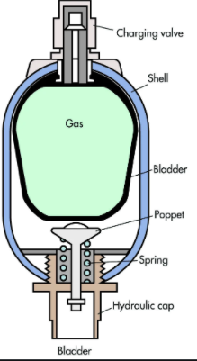
Accumulator is a pressure vessel for storing hydraulic pressure in it utilizing compressible and decompressible nature of nitrogen gas. So, it can be said that the accumulator has a similar function to the rechargeable electrical battery.
In electricity, electrical energy is stored to the battery. On the other hand, in the hydraulic field, fluid energy (pressure of the fluid) is stored in an accumulator and is discharged when required.
Explain with neat sketch (position based) working of sequencing circuit for two double acting Air cylinders.
Answer:
Explain with neat sketch (position based) working of sequencing circuit for two double acting Air cylinders. Pneumatic double acting cylinders can be operated sequentially using a sequence valve or by using position-based method. In pneumatics, use of sequence valve is not popular. Position based sequencing is possible using roller operated DCV or solenoid operated DCV. Various components required for Position based sequencing using roller operated DCV are as follows. I. Double acting cylinder - 02 Nos. II. 3/2 roller operated DCV – 02 Nos. III. 4/2 or 5/2 DCV – 01 No. IV. FRL Unit, Compressed air supply, hose pipes etc. Components are connected as shown in figure.
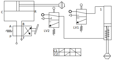
Working: In the first position of lever of 4/2 DCV (5/2 DCV can be used), the DAC extends. By the end of extension of first DAC, the cam presses roller of valve LV1 hence compressed air flows to second DAC, and second DAC extends. When the lever of 4/2 DCV is shifted to second position, DAC retracts. By the end of retraction of first DAC, the cam presses roller valve LV2, hence compresses air flows to second DAC and second DAC retracts.
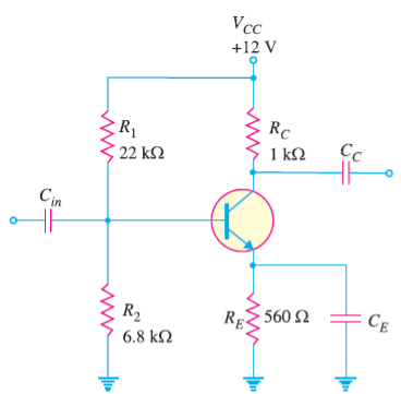
Select a suitable value for the emitter bypass capacitor in Fig. 1 if the amplifier is to operate over a frequency range from 2 kHz to 10 kHz.
Solution:
An amplifier usually handles more than one frequency. Therefore, the value of CE is so selected that it provides adequate bypassing for the lowest of all the frequencies. Then it will also be a good bypass ( XC ∝ 1/f ) for all the higher frequencies.
References:
1. Basic Mechanical Engineering, G Shanmugam, S Ravindran, McGraw Hill
2. Basic Mechanical Engineering, M P Poonia and S C Sharma, Khanna Publishers
3. Mechatronics: Principles, Concepts and Applications, Nitaigour Mahalik, McGraw Hill
4. Mechatronics, as per AICTE: Integrated Mechanical Electronic Systems, K.P. Ramachandran, G.K. Vijayaraghavan, M.S. Balasundaram, Wiley India
5. Mechanical Measurements & Control, Dr. D. S. Kumar. Metropolitan Book Company