Unit – 3
Control Unit
There are various types of machine instructions, in a computer, that must be sufficient to express any of the instruction from a HLL.
Types of instructions that must be included in a practical computer are as follows:
1. Data Processing Instruction
2. Data Storage and Retrieval Instruction
3. Data Moment Instructions
4. Control Flow Instructions
5. Miscellaneous Instructions
1. Data Processing Instruction:
Data Processing Instructions contain arithmetic and Logic Instructions. That is, these instructions are used for arithmetic and logic operations in a machine.
Example of these instructions are:
-Arithmetic Instructions such as add and subtract
-Logic instructions such as AND, OR, and NOT
In short, we can say that, Arithmetic Instructions provide computational capabilities for processing numeric data. And Logical (Boolean) Instructions operate on bits of word as bits rather than as numbers. These operations primarily performed on data stored in processor register.
2. Data Storage and Retrieval instructions:
Since Data Processing Operations are normally performed on the data in CPU register. Therefore, there is a need of an instructions to bring data to and from memory register. Such instructions are called Data Storage and Retrieval instructions.
As an example: Load and Store Instructions.
3. Data Moment Instructions:
These are basically input/output instructions. And I/O instructions are needed to transfer program and data into memory and the result of computations back out to the user.
That is, these instructions are used to bring in programs and data from various devices (specifically Input) to memory or to communicate the result to the output device.
Example of these Instructions include: Input, Output and Move etc.
4. Control Flow Instructions:
Control flow Instructions are used to control the flow of instruction of a program. It includes test and branch instructions, where,
"Test instructions" are used to test the status of computation through value of data word, and,"Branch instructions" are used to branch to a different set of instructions depending on the decision made. Besides this, branch instructions are also used for transfer of control.
5. Miscellaneous Instructions:
These are some more instructions which do not fit in any of the above categories.
Example of these instructions are: Interrupt or Supervisory Call, Halt instruction or some or more instructions of operating system.
There are basically three types of instruction format are there:
Zero, One, Two and Three Address Instruction
1- Zero Address Instructions.
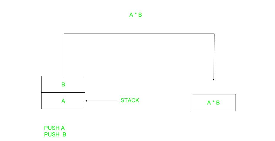
- A stack-based computer does not use the address field in the instruction. To evaluate an expression first it is converted to revere Polish Notation i.e., Postfix Notation.
Example:
Expression: X = (A+B) *(C+D)
Postfixed: X = AB+CD+*
TOP means top of stack
M[X] is any memory location
PUSH | A | TOP = A |
PUSH | B | TOP = B |
ADD |
| TOP = A+B |
PUSH | C | TOP = C |
PUSH | D | TOP = D |
ADD |
| TOP = C+D |
MUL |
| TOP = (C+D) *(A+B) |
POP | X | M[X] = TOP |
|
|
|
2-One Address Instructions.
This uses an implied ACCUMULATOR register for data manipulation. One operand is in the accumulator and the other is in the register or memory location. Implied means that the CPU already knows that one operand is in the accumulator so there is no need to specify it.

Example:
Expression: X = (A+B) *(C+D)
AC is accumulator
M [] is any memory location
M[T] is temporary location
LOAD | A | AC = M[A] |
ADD | B | AC = AC + M[B] |
STORE | T | M[T] = AC |
LOAD | C | AC = M[C] |
ADD | D | AC = AC + M[D] |
MUL | T | AC = AC * M[T] |
STORE | X | M[X] = AC |
3-Three Address Instructions.
This has three address field to specify a register or a memory location. Program created are much short in size but number of bits per instruction increase. These instructions make creation of program much easier but it does not mean that program will run much faster because now instruction only contain more information but each micro-operation (changing content of register, loading address in address bus etc.) will be performed in one cycle only.

Example:
Expression: X = (A+B) *(C+D)
R1, R2 are registers
M [] is any memory location
ADD |
| R1, A, B | R1 = M[A] + M[B] |
ADD |
| R2, C, D | R2 = M[C] + M[D] |
MUL |
| X, R1, R2 | M[X] = R1 * R2 |
The Instruction Cycle –
Each phase of Instruction Cycle can be decomposed into a sequence of elementary micro-operations. In the above examples, there is one sequence each for the Fetch, Indirect, Execute and Interrupt Cycles.
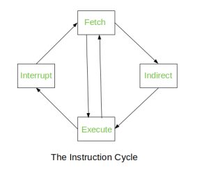
Fig – Instruction Cycle
The Indirect Cycle is always followed by the Execute Cycle. The Interrupt Cycle is always followed by the Fetch Cycle. For both fetch and execute cycles, the next cycle depends on the state of the system.
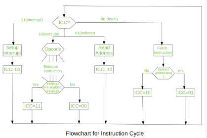
Fig – Flowchart of instruction cycle
We assumed a new 2-bit register called Instruction Cycle Code (ICC). The ICC designates the state of processor in terms of which portion of the cycle it is in:
00: Fetch Cycle
01: Indirect Cycle
10: Execute Cycle
11: Interrupt Cycle
At the end of each cycle, the ICC is set appropriately. The above flowchart of Instruction Cycle describes the complete sequence of micro-operations, depending only on the instruction sequence and the interrupt pattern (this is a simplified example). The operation of the processor is described as the performance of a sequence of micro-operation.
The Fetch Cycle –
At the beginning of the fetch cycle, the address of the next instruction to be executed is in the Program Counter (PC).
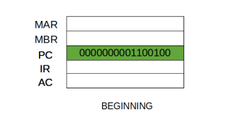
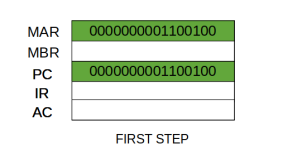
Step 1: The address in the program counter is moved to the memory address register (MAR), as this is the only register which is connected to address lines of the system bus.
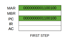
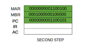
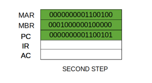
Step 2: The address in MAR is placed on the address bus, now the control unit issues a READ command on the control bus, and the result appears on the data bus and is then copied into the memory buffer register (MBR). Program counter is incremented by one, to get ready for the next instruction. (These two actions can be performed simultaneously to save time)
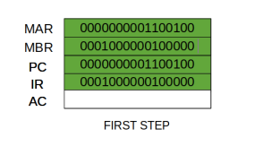
Step 3: The content of the MBR is moved to the instruction register (IR).
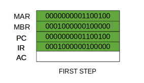
Thus, a simple Fetch Cycle consist of three steps and four micro-operations. Symbolically, we can write these sequence of events as follows:
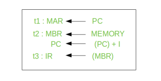
Here ‘I’ is the instruction length. The notations (t1, t2, t3) represents successive time units. We assume that a clock is available for timing purposes and it emits regularly spaced clock pulses. Each clock pulse defines a time unit. Thus, all time units are of equal duration. Each micro-operation can be performed within the time of a single time unit. First time unit: Move the contents of the PC to MAR.
Second time unit: Move contents of memory location specified by MAR to MBR. Increment content of PC by I. Third time unit: Move contents of MBR to IR.
Note: Second and third micro-operations both take place during the second time unit.
In computer central processing units, micro-operations (also known as micro-ops) are the functional or atomic, operations of a processor. These are low level instructions used in some designs to implement complex machine instructions.
They generally perform operations on data stored in one or more registers. They transfer data between registers or between external buses of the CPU, also performs arithmetic and logical operations on registers.
In executing a program, operation of a computer consists of a sequence of instruction cycles, with one machine instruction per cycle. Each instruction cycle is made up of a number of smaller units – Fetch, Indirect, Execute and Interrupt cycles. Each of these cycles involves series of steps, each of which involves the processor registers. These steps are referred as micro-operations. The prefix micro refers to the fact that each of the step is very simple and accomplishes very little.
Figure below depicts the concept being discussed here.
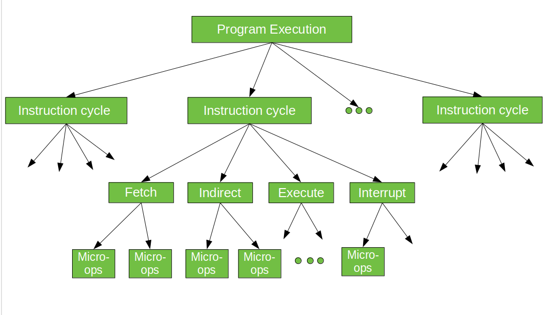
Execution of a program consists of sequential execution of instructions. Each instruction is executed during an instruction cycle made up of shorter sub-cycles (example – fetch, indirect, execute, and interrupt).
The performance of each sub-cycle involves one or more shorter operations, that is, micro-operations.
Registers Involved in Each Instruction Cycle:
- Memory address registers (MAR): It is connected to the address lines of the system bus. It specifies the address in memory for a read or write operation.
- Memory Buffer Register (MBR): It is connected to the data lines of the system bus. It contains the value to be stored in memory or the last value read from the memory.
- Program Counter (PC): Holds the address of the next instruction to be fetched.
- Instruction Register (IR): Holds the last instruction fetched.
The Instruction Cycle –
Each phase of Instruction Cycle can be decomposed into a sequence of elementary micro-operations. In the above examples, there is one sequence each for the Fetch, Indirect, Execute and Interrupt Cycles.
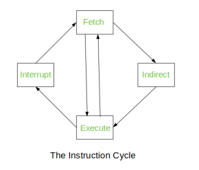
Fig – Instruction Cycle
The Indirect Cycle is always followed by the Execute Cycle. The Interrupt Cycle is always followed by the Fetch Cycle. For both fetch and execute cycles, the next cycle depends on the state of the system.
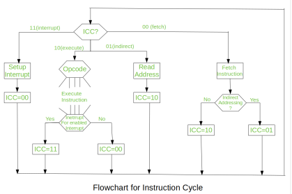
Fig – Flowchart of instruction cycle
We assumed a new 2-bit register called Instruction Cycle Code (ICC). The ICC designates the state of processor in terms of which portion of the cycle it is in:
00: Fetch Cycle
01: Indirect Cycle
10: Execute Cycle
11: Interrupt Cycle
At the end of each cycle, the ICC is set appropriately. The above flowchart of Instruction Cycle describes the complete sequence of micro-operations, depending only on the instruction sequence and the interrupt pattern (this is a simplified example). The operation of the processor is described as the performance of a sequence of micro-operation.
Different Instruction Cycles:
The Fetch Cycle –
At the beginning of the fetch cycle, the address of the next instruction to be executed is in the Program Counter (PC).
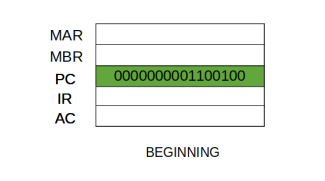
Step 1: The address in the program counter is moved to the memory address register (MAR), as this is the only register which is connected to address lines of the system bus.
Step 2: The address in MAR is placed on the address bus, now the control unit issues a READ command on the control bus, and the result appears on the data bus and is then copied into the memory buffer register (MBR). Program counter is incremented by one, to get ready for the next instruction. (These two actions can be performed simultaneously to save time)
Step 3: The content of the MBR is moved to the instruction register (IR).
Thus, a simple Fetch Cycle consist of three steps and four micro-operations. Symbolically, we can write these sequence of events as follows:
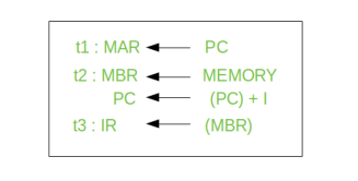
Here ‘I’ is the instruction length. The notations (t1, t2, t3) represents successive time units. We assume that a clock is available for timing purposes and it emits regularly spaced clock pulses. Each clock pulse defines a time unit. Thus, all time units are of equal duration. Each micro-operation can be performed within the time of a single time unit. First time unit: Move the contents of the PC to MAR.
Second time unit: Move contents of memory location specified by MAR to MBR. Increment content of PC by I. Third time unit: Move contents of MBR to IR.
Note: Second and third micro-operations both take place during the second time unit.
The Indirect Cycles –
Once an instruction is fetched, the next step is to fetch source operands. Source Operand is being fetched by indirect addressing (it can be fetched by any addressing mode, here it’s done by indirect addressing). Register-based operands need not be fetched. Once the opcode is executed, a similar process may be needed to store the result in main memory. Following micro-operations takes place:
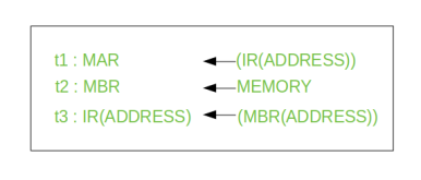
Step 1: The address field of the instruction is transferred to the MAR. This is used to fetch the address of the operand.
Step 2: The address field of the IR is updated from the MBR. (So that it now contains a direct addressing rather than indirect addressing)
Step 3: The IR is now in the state, as if indirect addressing has not been occurred.
Note: Now IR is ready for the execute cycle, but it skips that cycle for a moment to consider the Interrupt Cycle.
The Execute Cycle
The other three cycles (Fetch, Indirect and Interrupt) are simple and predictable. Each of them requires simple, small and fixed sequence of micro-operation. In each case same micro-operation are repeated each time around.
Execute Cycle is different from them. Like, for a machine with N different opcodes there are N different sequence of micro-operations that can occur.
Let’s take a hypothetical example:
Consider an add instruction:

Here, this instruction adds the content of location X to register R. Corresponding micro-operation will be:
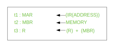
We begin with the IR containing the ADD instruction.
Step 1: The address portion of IR is loaded into the MAR.
Step 2: The address field of the IR is updated from the MBR, so the reference memory location is read.
Step 3: Now, the contents of R and MBR are added by the ALU.
Let’s take a complex example:

Here, the content of location X is incremented by 1. If the result is 0, the next instruction will be skipped. Corresponding sequence of micro-operation will be:
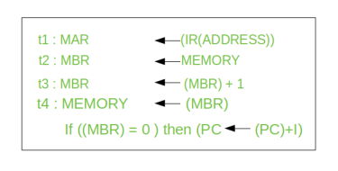
Here, the PC is incremented if (MBR) = 0. This test (is MBR equal to zero or not) and action (PC is incremented by 1) can be implemented as one micro-operation.
Note: This test and action micro-operation can be performed during the same time unit during which the updated value MBR is stored back to memory.
The Interrupt Cycle:
At the completion of the Execute Cycle, a test is made to determine whether any enabled interrupt has occurred or not. If an enabled interrupt has occurred then Interrupt Cycle occurs. The nature of this cycle varies greatly from one machine to another.
Let’s take a sequence of micro-operation:
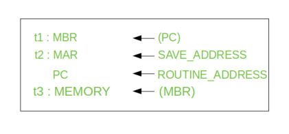
Step 1: Contents of the PC is transferred to the MBR, so that they can be saved for return.
Step 2: MAR is loaded with the address at which the contents of the PC are to be saved.
PC is loaded with the address of the start of the interrupt-processing routine.
Step 3: MBR, containing the old value of PC, is stored in memory.
Note: In step 2, two actions are implemented as one micro-operation. However, most processor provide multiple types of interrupts, it may take one or more micro-operation to obtain the save_address and the routine_address before they are transferred to the MAR and PC respectively.
Key takeaways
- Memory address registers (MAR): It is connected to the address lines of the system bus. It specifies the address in memory for a read or write operation.
- Memory Buffer Register (MBR): It is connected to the data lines of the system bus. It contains the value to be stored in memory or the last value read from the memory.
- Program Counter (PC): Holds the address of the next instruction to be fetched.
- Instruction Register (IR): Holds the last instruction fetched.
Program Control Instructions are the machine code that is used by machine or in assembly language by user to command the processor act accordingly.
These instructions are of various types.
These are used in assembly language by user also. But in level language, user code is translated into machine code and thus instructions are passed to instruct the processor do the task.
Types of Program Control Instructions.
1. Compare Instruction.
Compare instruction is specifically provided, which is similar t a subtract instruction except the result is not stored anywhere, but flags are set according to the result.
Example:
CMP R1, R2;
2. Unconditional Branch Instruction.
It causes an unconditional change of execution sequence to a new location.
Example:
JUMP L2
Mov R3, R1 goto L2
3. Conditional Branch Instruction.
A conditional branch instruction is used to examine the values stored in the condition code register to determine whether the specific condition exists and to branch if it does.
Example:
Assembly Code: BE R1, R2, L1
Compiler allocates R1 for x and R2 for y
High Level Code: if (x==y) goto L1;
4. Subroutines
A subroutine is a program fragment that lives in user space, performs a well-defined task. It is invoked by another user program and returns control to the calling program when finished.
Example:
CALL and RET
5. Halting Instructions
- NOP Instruction – NOP is no operation. It causes no change in the processor state other than an advancement of the program counter. It can be used to synchronize timing.
- HALT – It brings the processor to an orderly halt, remaining in an idle state until restarted by interrupt, trace, reset or external action.
6. Interrupt Instructions
Interrupt is a mechanism by which an I/O or an instruction can suspend the normal execution of processor and get itself serviced.
- RESET – It reset the processor. This may include any or all setting registers to an initial value or setting program counter to standard starting location.
- TRAP – It is non-maskable edge and level triggered interrupt. TRAP has the highest priority and vectored interrupt.
- INTR – It is level triggered and maskable interrupt. It has the lowest priority. It can be disabled by resetting the processor.
Reduced Instruction Set Architecture
The main idea behind is to make hardware simpler by using an instruction set composed of a few basic steps for loading, evaluating, and storing operations just like a load command will load data, store command will store the data.
Characteristic of RISC –
- Simpler instruction, hence simple instruction decoding.
- Instruction comes undersize of one word.
- Instruction takes a single clock cycle to get executed.
- More number of general-purpose registers.
- Simple Addressing Modes.
- Less Data types.
- Pipeline can be achieved.
Note- RISC approach- Here programmer will write the first load command to load data in registers then it will use a suitable operator and then it will store the result in the desired location.
RISC processor has 5 stage instruction pipelines to execute all the instructions in the RISC instruction set. Following are the 5 stages of RISC pipeline with their respective operations.
- Stage 1 (Instruction Fetch)
In this stage the CPU reads instructions from the address in the memory whose value is present in the program counter. - Stage 2 (Instruction Decode)
In this stage, instruction is decoded and the register file is accessed to get the values from the registers used in the instruction. - Stage 3 (Instruction Execute)
In this stage, ALU operations are performed. - Stage 4 (Memory Access)
In this stage, memory operands are read and written from/to the memory that is present in the instruction. - Stage 5 (Write Back)
In this stage, computed/fetched value is written back to the register present in the instructions.
The term Pipelining refers to a technique of decomposing a sequential process into sub-operations, with each sub-operation being executed in a dedicated segment that operates concurrently with all other segments.
The most important characteristic of a pipeline technique is that several computations can be in progress in distinct segments at the same time. The overlapping of computation is made possible by associating a register with each segment in the pipeline. The registers provide isolation between each segment so that each can operate on distinct data simultaneously.
The structure of a pipeline organization can be represented simply by including an input register for each segment followed by a combinational circuit.
Let us consider an example of combined multiplication and addition operation to get a better understanding of the pipeline organization.
The combined multiplication and addition operation is done with a stream of numbers such as:
Ai* Bi + Ci for i = 1, 2, 3, ......., 7
The operation to be performed on the numbers is decomposed into sub-operations with each sub-operation to be implemented in a segment within a pipeline.
The sub-operations performed in each segment of the pipeline are defined as:
R1 ← Ai, R2 ← Bi Input Ai, and Bi
R3 ← R1 * R2, R4 ← Ci Multiply, and input Ci
R5 ← R3 + R4 Add Ci to product
The following block diagram represents the combined as well as the sub-operations performed in each segment of the pipeline.
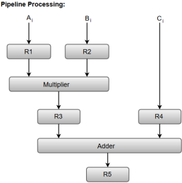
Fig – Pipeline process
Registers R1, R2, R3, and R4 hold the data and the combinational circuits operate in a particular segment.
The output generated by the combinational circuit in a given segment is applied as an input register of the next segment. For instance, from the block diagram, we can see that the register R3 is used as one of the input registers for the combinational adder circuit.
In general, the pipeline organization is applicable for two areas of computer design which includes:
- Arithmetic Pipeline
- Instruction Pipeline
Instruction Pipeline
Pipeline processing can occur not only in the data stream but in the instruction stream as well.
Most of the digital computers with complex instructions require instruction pipeline to carry out operations like fetch, decode and execute instructions.
In general, the computer needs to process each instruction with the following sequence of steps.
- Fetch instruction from memory.
- Decode the instruction.
- Calculate the effective address.
- Fetch the operands from memory.
- Execute the instruction.
- Store the result in the proper place.
Each step is executed in a particular segment, and there are times when different segments may take different times to operate on the incoming information. Moreover, there are times when two or more segments may require memory access at the same time, causing one segment to wait until another is finished with the memory.
The organization of an instruction pipeline will be more efficient if the instruction cycle is divided into segments of equal duration. One of the most common examples of this type of organization is a Four-segment instruction pipeline.
A four-segment instruction pipeline combines two or more different segments and makes it as a single one. For instance, the decoding of the instruction can be combined with the calculation of the effective address into one segment.
The following block diagram shows a typical example of a four-segment instruction pipeline. The instruction cycle is completed in four segments.
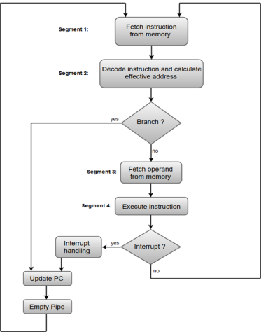
Fig – Instruction Cycle
Segment 1:
The instruction fetch segment can be implemented using first in, first out (FIFO) buffer.
Segment 2:
The instruction fetched from memory is decoded in the second segment, and eventually, the effective address is calculated in a separate arithmetic circuit.
Segment 3:
An operand from memory is fetched in the third segment.
Segment 4:
The instructions are finally executed in the last segment of the pipeline organization.
Arithmetic Pipeline
Arithmetic Pipelines are mostly used in high-speed computers. They are used to implement floating-point operations, multiplication of fixed-point numbers, and similar computations encountered in scientific problems.
To understand the concepts of arithmetic pipeline in a more convenient way, let us consider an example of a pipeline unit for floating-point addition and subtraction.
The inputs to the floating-point adder pipeline are two normalized floating-point binary numbers defined as:
X = A * 2a = 0.9504 * 103
Y = B * 2b = 0.8200 * 102
Where A and B are two fractions that represent the mantissa and a and b are the exponents.
The combined operation of floating-point addition and subtraction is divided into four segments. Each segment contains the corresponding sub operation to be performed in the given pipeline. The sub operations that are shown in the four segments are:
- Compare the exponents by subtraction.
- Align the mantissas.
- Add or subtract the mantissas.
- Normalize the result.
We will discuss each sub operation in a more detailed manner later in this section.
The following block diagram represents the sub operations performed in each segment of the pipeline.
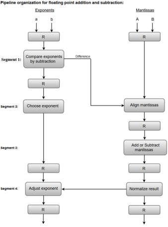
Fig – Sub Operations
Note: Registers are placed after each sub operation to store the intermediate results.
1. Compare exponents by subtraction:
The exponents are compared by subtracting them to determine their difference. The larger exponent is chosen as the exponent of the result.
The difference of the exponents, i.e., 3 - 2 = 1 determines how many times the mantissa associated with the smaller exponent must be shifted to the right.
2. Align the mantissas:
The mantissa associated with the smaller exponent is shifted according to the difference of exponents determined in segment one.
X = 0.9504 * 103
Y = 0.08200 * 103
3. Add mantissas:
The two mantissas are added in segment three.
Z = X + Y = 1.0324 * 103
4. Normalize the result:
After normalization, the result is written as:
Z = 0.1324 * 104
Key takeaway
The term Pipelining refers to a technique of decomposing a sequential process into sub-operations, with each sub-operation being executed in a dedicated segment that operates concurrently with all other segments.
The most important characteristic of a pipeline technique is that several computations can be in progress in distinct segments at the same time. The overlapping of computation is made possible by associating a register with each segment in the pipeline. The registers provide isolation between each segment so that each can operate on distinct data simultaneously.
Hardwired Control
The Hardwired Control organization involves the control logic to be implemented with gates, flip-flops, decoders, and other digital circuits.
The following image shows the block diagram of a Hardwired Control organization.
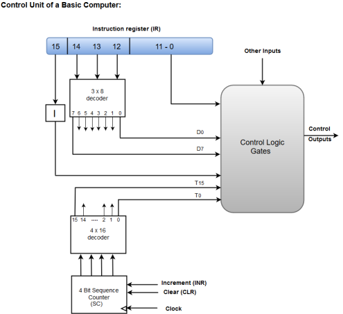
Figure – Control unit of a basic computer
- A Hard-wired Control consists of two decoders, a sequence counter, and a number of logic gates.
- An instruction fetched from the memory unit is placed in the instruction register (IR).
- The component of an instruction register includes; I bit, the operation code, and bits 0 through 11.
- The operation code in bits 12 through 14 are coded with a 3 x 8 decoder.
- The outputs of the decoder are designated by the symbols D0 through D7.
- The operation code at bit 15 is transferred to a flip-flop designated by the symbol I.
- The operation codes from Bits 0 through 11 are applied to the control logic gates.
- The Sequence counter (SC) can count in binary from 0 through 15.
Micro-programmed Control
The Microprogrammed Control organization is implemented by using the programming approach.
In Microprogrammed Control, the micro-operations are performed by executing a program consisting of micro-instructions.
The following image shows the block diagram of a Microprogrammed Control organization.

Figure – Microprogrammed control unit of a basic computer
- The Control memory address register specifies the address of the micro-instruction.
- The Control memory is assumed to be a ROM, within which all control information is permanently stored.
- The control register holds the microinstruction fetched from the memory.
- The micro-instruction contains a control word that specifies one or more micro-operations for the data processor.
- While the micro-operations are being executed, the next address is computed in the next address generator circuit and then transferred into the control address register to read the next microinstruction.
- The next address generator is often referred to as a micro-program sequencer, as it determines the address sequence that is read from control memory.
Micro Instructions Sequencer is a combination of all hardware for selecting the next micro-instruction address. The micro-instruction in control memory contains a set of bits to initiate micro-operations in computer registers and other bits to specify the method by which the address is obtained.
Implementation of Micro Instructions Sequencer in figure shown below
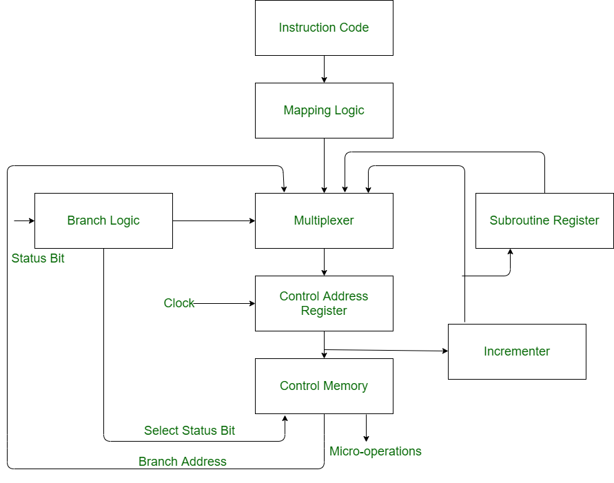
Control Address Register (CAR):
Control address register receives the address from four different paths. For receiving the addresses from four different paths, Multiplexer is used.
- Multiplexer:
Multiplexer is a combinational circuit which contains many data inputs and single data output depending on control or select inputs.
- Branching:
Branching is achieved by specifying the branch address in one of the fields of the micro instruction. Conditional branching is obtained by using part of the micro-instruction to select a specific status bit in order to determine its condition.
- Mapping Logic:
An external address is transferred into control memory via a mapping logic circuit.
- Incrementor:
Incrementer increments the content of the control address register by one, to select the next micro-instruction in sequence.
- Subroutine Register (SBR):
The return address for a subroutine is stored in a special register called Subroutine Register whose value is then used when the micro-program wishes to return from the subroutine.
- Control Memory:
Control memory is a type of memory which contains addressable storage registers. Data is temporarily stored in control memory. Control memory can be accessed quicker than main memory.
A language is used to deign micro programmed control unit known as a microprogramming language. Each line describes a set of micro-operations occurring at one time and is known as a microinstruction. A sequence of instructions is known as a micro program, or firmware.
For each micro-operation, control unit has to do is generate a set of control signals. Thus, for any micro-operation, control line emanating from the control unit is either on or off. This condition can, be represented by a binary digit for each control line. So, we could construct a control word in which each bit represents one control line. Now add an address field to each control word, indicating the location of the next control word to be executed if a certain condition is true.
The result is known as a horizontal microinstruction, which is shown in Figure below. The format of the microinstruction or control word is as follows. There is one bit for each internal processor control line and one bit for each system bus control line.
There is a condition field indicating the condition under which there should be a branch, and there is a field with the address of the microinstruction to be executed next when a branch is taken.
Such a microinstruction is interpreted as follows:
1 - To execute this microinstruction, turn on all the control lines indicated by a 1 bit leave off all control lines indicated by a 0 bit.
The resulting control signals will cause one or more micro-operations to be performed.
2 If the condition indicated by the condition bits is false, execute the next microinstruction in sequence.
3 If the condition indicated by the condition bits is true, the next microinstruction to be executed is indicated in the address field
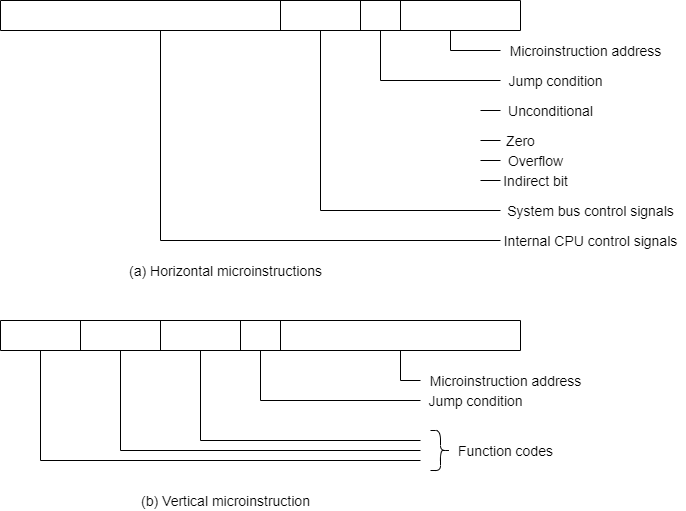
Fig - Typical Micro Instruction Format
In a vertical microinstruction, a code is used for each action to be performed, and the decoder translates this code into individual control signals. The advantage of vertical microinstructions is that they are more compact (fewer bits) than horizontal microinstructions.
In Figure below shows how these control words or microinstructions could be arranged in a control memory. The microinstructions in each routine are to be executed sequentially. Each routine ends with a branch or jump instruction indicating where to go next.
There is a special execute cycle routine whose only purpose is to signify that one of the machine instruction routines (AND, ADD, and so on) is to be executed next, depending on the current opcode.
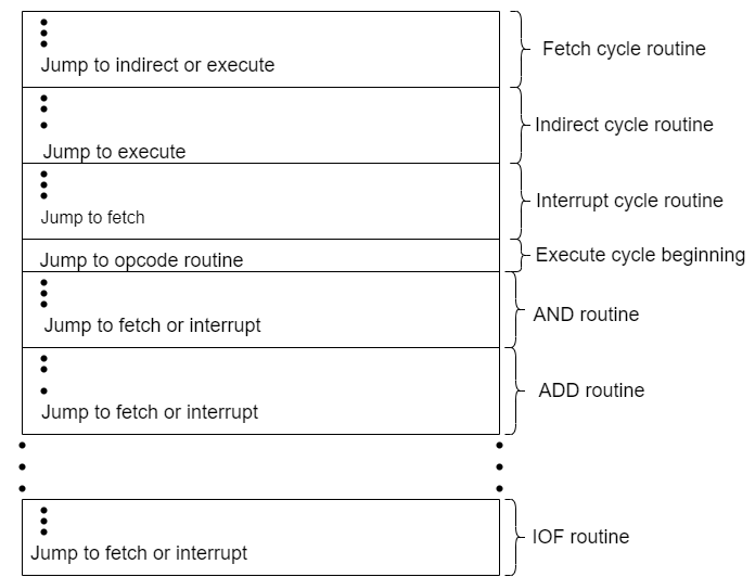
Fig-Organization of Control Memory
References:
1. Computer System Architecture - M. Mano
2. Carl Hamacher, Zvonko Vranesic, Safwat Zaky Computer Organization, McGraw-Hill, Fifth Edition, Reprint 2012
3. John P. Hayes, Computer Architecture and Organization, Tata McGraw Hill, Third Edition, 1998. Reference books
4. William Stallings, Computer Organization and Architecture-Designing for Performance, Pearson Education, Seventh edition, 2006.
5. Behrooz Parahami, “Computer Architecture”, Oxford University Press, Eighth Impression, 2011.