Unit – 5
Input / Output
Peripheral Devices:
The Input / output organization of computer depends upon the size of computer and the peripherals connected to it. The I/O Subsystem of the computer, provides an efficient mode of communication between the central system and the outside environment.
There are three types of peripherals:
- Input peripherals: Allows user input, from the outside world to the computer. Example: Keyboard, Mouse etc.
- Output peripherals: Allows information output, from the computer to the outside world. Example: Printer, Monitor etc
- Input-Output peripherals: Allows both input(from outside world to computer) as well as, output(from computer to the outside world). Example: Touch screen etc.
The Major Differences between peripheral devices and CPU:
1. Peripherals are electromechnical and electromagnetic devices and CPU and memory are electronic devices. Therefore, a conversion of signal values may be needed.
2. The data transfer rate of peripherals is usually slower than the transfer rate of CPU and consequently, a synchronization mechanism may be needed.
3. Data codes and formats in the peripherals differ from the word format in the CPU and memory.
4. The operating modes of peripherals are different from each other and must be controlled so as not to disturb the operation of other peripherals connected to the CPU.
To resolve these differences, computer systems include special hardware components between the CPU and Peripherals to supervises and synchronizes all input and out transfers. These components are called Interface Units because they interface between the processor bus and the peripheral devices.
Input-Output Interface:
Peripherals connected to a computer need special communication links for interfacing with CPU. In computer system, there are special hardware components between the CPU and peripherals to control or manage the input-output transfers.
These components are called input-output interface units because they provide communication links between processor bus and peripherals. They provide a method for transferring information between internal system and input-output devices.
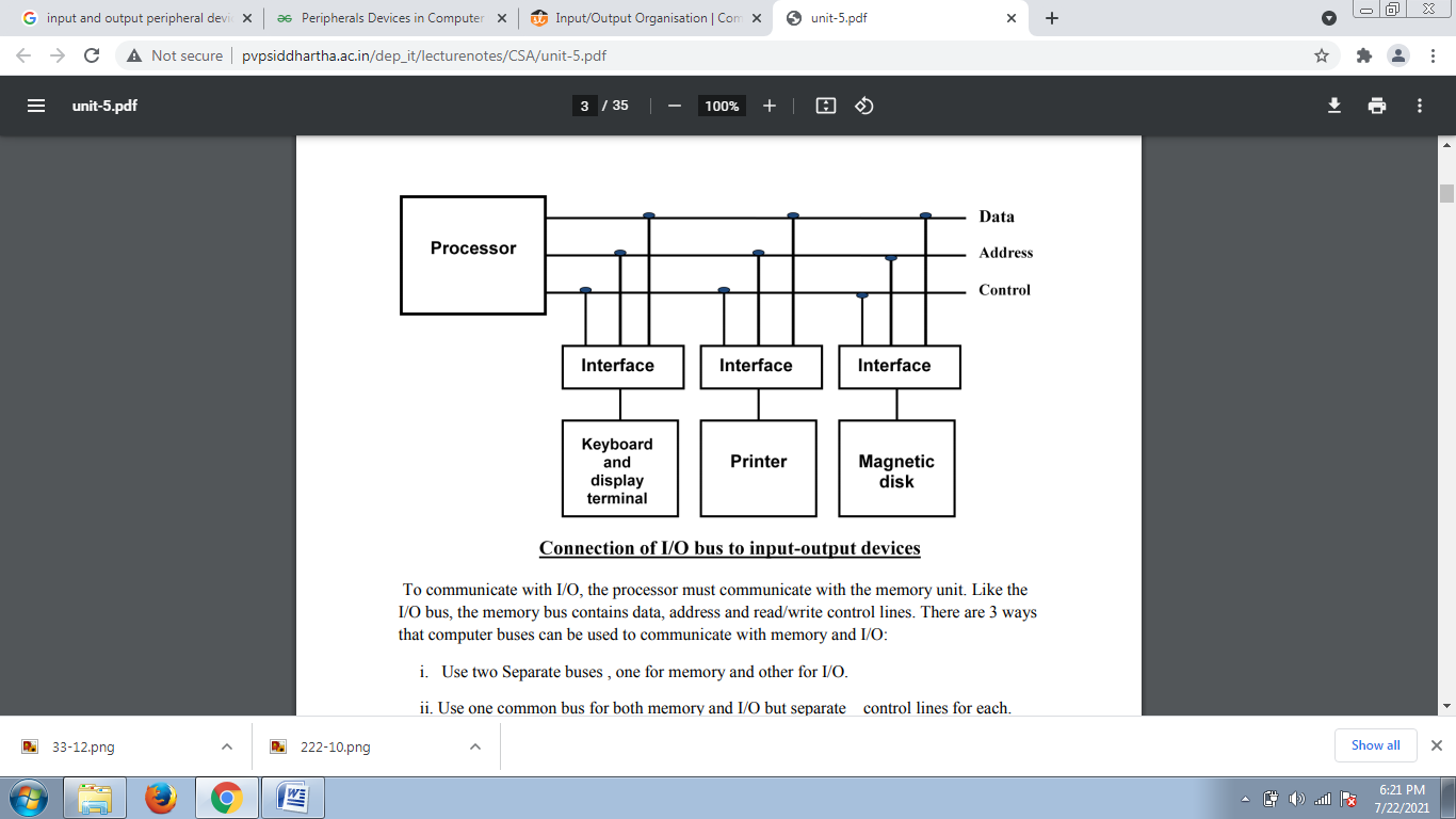
Input-Output Interface
1. Data Bus Buffer
2. Read/Write Control Logic
3. Port A, Port B register
4. Control and Status register
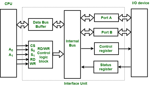
Figure – Interface Unit
These are explained as following below.
Data Bus Buffer:
The bus buffer use bi-directional data bus to communicate with CPU. All control word data and status information between interface unit and CPU are transferred through data bus.
Port A and Port B:
Port A and Port B are used to transfer data between Input-Output device and Interface Unit. Each port consists of bi-directional data input buffer and bi-directional data output buffer. Interface unit connect directly with an input device and output disk or with device that require both input and output through Port A and Port B i.e. modem, external hard-drive, magnetic disk.
Control and Status Register:
CPU gives control information to control register on basis of control information. Interface unit control input and output operation between CPU and input-output device. Bits which are present in status register are used for checking of status conditions. Status register indicate status of data register, port A, port B and also record error that may be occur during transfer of data.
Read/Write Control Logic:
This block generates necessary control signals for overall device operations. All commands from CPU are accepted through this block. It also allow status of interface unit to be transferred onto data bus through this block accept CS, read and write control signal from system bus and S0, S1 from system address bus. Read and Write signal are used to define direction of data transfer over data bus.
Read Operation: CPU <---- I/O device
Write Operation: CPU ----> I/O device
The read signal direct data transfer from interface unit to CPU and write signal direct data transfer from CPU to interface unit through data bus.
Address bus is used to select to interface unit. Two least significant lines of address bus ( A0, A1 ) are connected to select lines S0, S1. This two select input lines are used to select any one of four registers in interface unit. The selection of interface unit is according to the following criteria:
Read state:
Chip Select | Operation | Select lines | Selection of
Interface unit | ||
CS | Read | Write | S | S | |
0 | 0 | 1 | 0 | 0 | Port A |
0 | 0 | 1 | 0 | 1 | Port B |
0 | 0 | 1 | 1 | 0 | Control Register |
0 | 0 | 1 | 1 | 1 | Status Register |
Write State:
Chip Select | Operation | Select lines | Selection of | ||
CS | Read | Write | S | S | |
0 | 1 | 0 | 0 | 0 | Port A |
0 | 1 | 0 | 0 | 1 | Port B |
0 | 1 | 0 | 1 | 0 | Control Register |
0 | 1 | 0 | 1 | 1 | Status Register |
Example:
If S0, S1 = 0 1, then Port B data register is selected for data transfer between CPU and I/O device.
If S0, S1 = 1 0, then Control register is selected and store the control information send by the CPU.
A connection point that acts as interface between the computer and external devices like mouse, printer, modem, etc. is called port.
Ports are of two types:
- Internal port: It connects the motherboard to internal devices like hard disk drive, CD drive, internal modem, etc.
- External port: It connects the motherboard to external devices like modem, mouse, printer, flash drives, etc.
Some of the most commonly used ports are shown below:
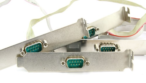
Serial Port
Serial ports transmit data sequentially one bit at a time. So they need only one wire to transmit 8 bits. However it also makes them slower. Serial ports are usually 9-pin or 25-pin male connectors. They are also known as COM (communication) ports or RS323C ports.
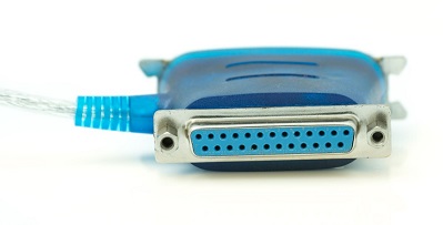
Parallel Port
Parallel ports can send or receive 8 bits or 1 byte at a time. Parallel ports come in form of 25-pin female pins and are used to connect printer, scanner, external hard disk drive, etc.
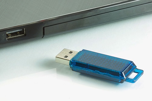
USB Port
USB stands for Universal Serial Bus. It is the industry standard for short distance digital data connection. USB port is a standardized port to connect a variety of devices like printer, camera, keyboard, speaker, etc.
PS-2 Port
PS/2 stands for Personal System/2. It is a female 6-pin port standard that connects to the male mini-DIN cable. PS/2 was introduced by IBM to connect mouse and keyboard to personal computers. This port is now mostly obsolete, though some systems compatible with IBM may have this port.
Infrared Port
Infrared port is a port that enables wireless exchange of data within a radius of 10m. Two devices that have infrared ports are placed facing each other so that beams of infrared lights can be used to share data.
Interrupt is a signal emitted by hardware or software when a process or an event needs immediate attention. It alerts the processor to a high priority process requiring interruption of the current working process. In I/O devices one of the bus control lines is dedicated for this purpose and is called the Interrupt Service Routine (ISR).
When a device raises an interrupt at let’s say process i, the processor first completes the execution of instruction i. Then it loads the Program Counter (PC) with the address of the first instruction of the ISR. Before loading the Program Counter with the address, the address of the interrupted instruction is moved to a temporary location. Therefore, after handling the interrupt the processor can continue with process i+1.
While the processor is handling the interrupts, it must inform the device that its request has been recognized so that it stops sending the interrupt request signal. Also, saving the registers so that the interrupted process can be restored in the future, increases the delay between the time an interrupt is received and the start of the execution of the ISR. This is called Interrupt Latency.
Hardware Interrupts:
In a hardware interrupt, all the devices are connected to the Interrupt Request Line. A single request line is used for all the n devices. To request an interrupt, a device closes its associated switch. When a device requests an interrupt, the value of INTR is the logical OR of the requests from individual devices.
Sequence of events involved in handling an IRQ:
- Devices raise an IRQ.
- Processor interrupts the program currently being executed.
- Device is informed that its request has been recognized and the device deactivates the request signal.
- The requested action is performed.
- Interrupt is enabled and the interrupted program is resumed.
Handling Multiple Devices:
When more than one device raises an interrupt request signal, then additional information is needed to decide which device to be considered first. The following methods are used to decide which device to select: Polling, Vectored Interrupts, and Interrupt Nesting. These are explained as following below.
- Polling:
In polling, the first device encountered with IRQ bit set is the device that is to be serviced first. Appropriate ISR is called to service the same. It is easy to implement but a lot of time is wasted by interrogating the IRQ bit of all devices.
2. Vectored Interrupts:
In vectored interrupts, a device requesting an interrupt identifies itself directly by sending a special code to the processor over the bus. This enables the processor to identify the device that generated the interrupt. The special code can be the starting address of the ISR or where the ISR is located in memory, and is called the interrupt vector.
3. Interrupt Nesting:
In this method, I/O device is organized in a priority structure. Therefore, interrupt request from a higher priority device is recognized where as request from a lower priority device is not. To implement this each process/device (even the processor). Processor accepts interrupts only from devices/processes having priority more than it.
Processors priority is encoded in a few bits of PS (Process Status register). It can be changed by program instructions that write into the PS. Processor is in supervised mode only while executing OS routines. It switches to user mode before executing application programs.
Key takeaways
- Interrupt is a signal emitted by hardware or software when a process or an event needs immediate attention. It alerts the processor to a high priority process requiring interruption of the current working process. In I/O devices one of the bus control lines is dedicated for this purpose and is called the Interrupt Service Routine (ISR).
- When a device raises an interrupt at let’s say process i, the processor first completes the execution of instruction i. Then it loads the Program Counter (PC) with the address of the first instruction of the ISR. Before loading the Program Counter with the address, the address of the interrupted instruction is moved to a temporary location. Therefore, after handling the interrupt the processor can continue with process i+1.
Types of interrupts
Interrupt is a signal emitted by hardware or software when a process or an event needs immediate attention. It alerts the processor to a high-priority process requiring interruption of the current working process.
In I/O devices one of the bus control lines is dedicated for this purpose and is called the Interrupt Service Routine (ISR).
When a device raises an interrupt at let’s say process i, the processor first completes the execution of instruction i. Then it loads the Program Counter (PC) with the address of the first instruction of the ISR. Before loading the Program Counter with the address, the address of the interrupted instruction is moved to a temporary location. Therefore, after handling the interrupt the processor can continue with process i+1.
While the processor is handling the interrupts, it must inform the device that its request has been recognized so that it stops sending the interrupt request signal. Also, saving the registers so that the interrupted process can be restored in the future, increases the delay between the time an interrupt is received and the start of the execution of the ISR. This is called Interrupt Latency.
Hardware Interrupts
In a hardware interrupt, all the devices are connected to the Interrupt Request Line. A single request line is used for all the n devices. To request an interrupt, a device closes its associated switch. When a device requests an interrupt, the value of INTR is the logical OR of the requests from individual devices.
Handling Multiple Devices
When more than one device raises an interrupt request signal, then additional information is needed to decide which device to be considered first. The following methods are used to decide which device to select: Polling, Vectored Interrupts, and Interrupt Nesting. These are explained as following below.
- Polling:
In polling, the first device encountered with the IRQ bit set is the device that is to be serviced first. Appropriate ISR is called to service the same. It is easy to implement but a lot of time is wasted by interrogating the IRQ bit of all devices. - Vectored Interrupts:
In vectored interrupts, a device requesting an interrupt identifies itself directly by sending a special code to the processor over the bus. This enables the processor to identify the device that generated the interrupt. The special code can be the starting address of the ISR or where the ISR is located in memory and is called the interrupt vector. - Interrupt Nesting:
In this method, the I/O device is organized in a priority structure. Therefore, an interrupt request from a higher priority device is recognized whereas a request from a lower priority device is not. To implement this each process/device (even the processor). The processor accepts interrupts only from devices/processes having priority more than it.
Exceptions
Exceptions and interrupts are unexpected events which will disrupt the normal flow of execution of instruction (that is currently executing by processor). An exception is an unexpected event from within the processor. Interrupt is an unexpected event from outside the process.
Whenever an exception or interrupt occurs, the hardware starts executing the code that performs an action in response to the exception. This action may involve killing a process, outputting an error message, communicating with an external device, or horribly crashing the entire computer system by initiating a “Blue Screen of Death” and halting the CPU. The instructions responsible for this action reside in the operating system kernel, and the code that performs this action is called the interrupt handler code. Now, We can think of handler code as an operating system subroutine. Then, After the handler code is executed, it may be possible to continue execution after the instruction where the execution or interrupt occurred.
Exception and Interrupt Handling:
Whenever an exception or interrupt occurs, execution transition from user mode to kernel mode where the exception or interrupt is handled. In detail, the following steps must be taken to handle an exception or interrupts.
While entering the kernel, the context (values of all CPU registers) of the currently executing process must first be saved to memory. The kernel is now ready to handle the exception/interrupt.
- Determine the cause of the exception/interrupt.
- Handle the exception/interrupt.
When the exception/interrupt have been handled the kernel performs the following steps:
- Select a process to restore and resume.
- Restore the context of the selected process.
- Resume execution of the selected process.
At any point in time, the values of all the registers in the CPU defines the context of the CPU. Another name used for CPU context is CPU state.
The exception/interrupt handler uses the same CPU as the currently executing process. When entering the exception/interrupt handler, the values in all CPU registers to be used by the exception/interrupt handler must be saved to memory. The saved register values can later restored before resuming execution of the process.
The handler may have been invoked for a number of reasons. The handler thus needs to determine the cause of the exception or interrupt. Information about what caused the exception or interrupt can be stored in dedicated registers or at predefined addresses in memory.
Next, the exception or interrupt needs to be serviced. For instance, if it was a keyboard interrupt, then the key code of the key press is obtained and stored somewhere or some other appropriate action is taken. If it was an arithmetic overflow exception, an error message may be printed or the program may be terminated.
The exception/interrupt have now been handled and the kernel. The kernel may choose to resume the same process that was executing prior to handling the exception/interrupt or resume execution of any other process currently in memory.
The context of the CPU can now be restored for the chosen process by reading and restoring all register values from memory.
The process selected to be resumed must be resumed at the same point it was stopped. The address of this instruction was saved by the machine when the interrupt occurred, so it is simply a matter of getting this address and make the CPU continue to execute at this address.
Key takeaways
- Exceptions and interrupts are unexpected events which will disrupt the normal flow of execution of instruction (that is currently executing by processor). An exception is an unexpected event from within the processor. Interrupt is an unexpected event from outside the process.
- Whenever an exception or interrupt occurs, the hardware starts executing the code that performs an action in response to the exception. This action may involve killing a process, outputting an error message, communicating with an external device, or horribly crashing the entire computer system by initiating a “Blue Screen of Death” and halting the CPU.
The mode of transferring information between internal storage and external I/O devices is known as I/O interface or input/output interface. The I/O module diagram is as follows
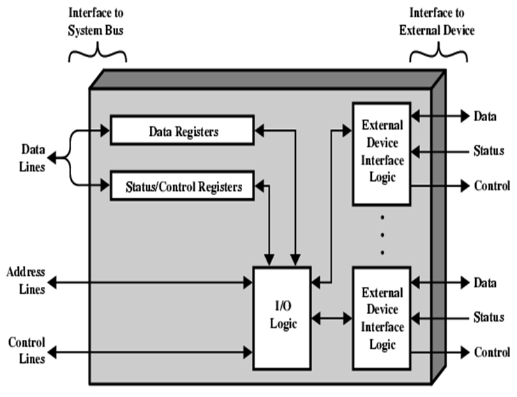
I/O Module Decisions
- Hide or reveal device properties to CPU
- Support multiple or single devices
- Control device functions or leave for CPU
- Also, O/S decisions – e.g. Unix treats everything it can as a file
Mode of Transfer
Data transfer between the central computer to I/O devices may be handled in variety of modes.
- –Programmed I/O
- –Interrupt Initiated I/O
- –Direct Memory Access (DMA)
Programmed I/O
- CPU requests I/O operation
- I/O module performs operations.
- I/O module sets status bits
- CPU checks status bits periodically
- I/O module does not inform CPU directly
- I/O module does not interrupt CPU
- CPU may wait or come back later
- Under programmed I/O data transfer is very like memory access (CPU viewpoint)
- Each device is given an unique identifier
- CPU commands contain identifier (address)
Disadvantage of Programmed I/O.
- The problem with programmed I/O is that the processor has to wait a long time for the I/O module of concern to be ready for either reception or transmission of data.
- The processor, while waiting, must repeatedly interrogate the status of the I/O module.
- Performance of the entire system is severely degraded.
Interrupt Driven I/O Basic Operation.
- CPU issues read command
- I/O module gets data from peripheral whilst CPU does other work
- I/O module interrupts CPU
- CPU requests data
- I/O module transfers data
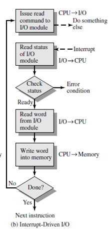
Working of CPU in terms of interrupts
- Issue read command.
- Do other work.
- Check for interrupt at end of each instruction cycle.
- If interrupted.
The method that is used to transfer information between internal storage and external I/O devices is known as I/O interface. The CPU is interfaced using special communication links by the peripherals connected to any computer system. These communication links are used to resolve the differences between CPU and peripheral. There exists special hardware components between CPU and peripherals to supervise and synchronize all the input and output transfers that are called interface units.
Mode of Transfer:
The binary information that is received from an external device is usually stored in the memory unit. The information that is transferred from the CPU to the external device is originated from the memory unit. CPU merely processes the information but the source and target is always the memory unit. Data transfer between CPU and the I/O devices may be done in different modes.
Data transfer to and from the peripherals may be done in any of the three possible ways
Programmed I/O.
Interrupt- initiated I/O.
Direct memory access(DMA)
Now let’s discuss each mode one by one.
Programmed I/O: It is due to the result of the I/O instructions that are written in the computer program. Each data item transfer is initiated by an instruction in the program. Usually, the transfer is from a CPU register and memory. In this case it requires constant monitoring by the CPU of the peripheral devices.
Example of Programmed I/O: In this case, the I/O device does not have direct access to the memory unit. A transfer from I/O device to memory requires the execution of several instructions by the CPU, including an input instruction to transfer the data from device to the CPU and store instruction to transfer the data from CPU to memory. In programmed I/O, the CPU stays in the program loop until the I/O unit indicates that it is ready for data transfer. This is a time-consuming process since it needlessly keeps the CPU busy. This situation can be avoided by using an interrupt facility. This is discussed below.
Interrupt- initiated I/O: Since in the above case we saw the CPU is kept busy unnecessarily. This situation can very well be avoided by using an interrupt driven method for data transfer. By using interrupt facility and special commands to inform the interface to issue an interrupt request signal whenever data is available from any device. In the meantime, the CPU can proceed for any other program execution. The interface meanwhile keeps monitoring the device. Whenever it is determined that the device is ready for data transfer it initiates an interrupt request signal to the computer. Upon detection of an external interrupt signal the CPU stops momentarily the task that it was already performing, branches to the service program to process the I/O transfer, and then return to the task it was originally performing.
Note: Both the methods programmed I/O and Interrupt-driven I/O require the active intervention of the
processor to transfer data between memory and the I/O module, and any data transfer must transverse
a path through the processor. Thus both these forms of I/O suffer from two inherent drawbacks.
The I/O transfer rate is limited by the speed with which the processor can test and service a
device.
The processor is tied up in managing an I/O transfer; a number of instructions must be executed
for each I/O transfer.
Direct Memory Access: The data transfer between a fast storage media such as magnetic disk and memory unit is limited by the speed of the CPU. Thus we can allow the peripherals directly communicate with each other using the memory buses, removing the intervention of the CPU. This type of data transfer technique is known as DMA or direct memory access. During DMA the CPU is idle and it has no control over the memory buses. The DMA controller takes over the buses to manage the transfer directly between the I/O devices and the memory unit.
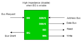
Figure – CPU bus signals for DMA Transfer
Bus Request: It is used by the DMA controller to request the CPU to relinquish the control of the buses.
Bus Grant: It is activated by the CPU to Inform the external DMA controller that the buses are in high impedance state and the requesting DMA can take control of the buses. Once the DMA has taken the control of the buses it transfers the data. This transfer can take place in many ways.
Types of DMA transfer using DMA controller:
Burst Transfer:
DMA returns the bus after complete data transfer. A register is used as a byte count,
being decremented for each byte transfer, and upon the byte count reaching zero, the DMAC will release the bus. When the DMAC operates in burst mode, the CPU is halted for the duration of the data transfer.
Steps involved are:
Bus grant request time.
Transfer the entire block of data at transfer rate of device because the device is usually slow than the
speed at which the data can be transferred to CPU.
Release the control of the bus back to CPU
So, total time taken to transfer the N bytes
= Bus grant request time + (N) * (memory transfer rate) + Bus release control time.
Where,
X µsec =data transfer time or preparation time (words/block)
Y µsec =memory cycle time or cycle time or transfer time (words/block)
% CPU idle (Blocked)=(Y/X+Y)*100
% CPU Busy=(X/X+Y)*100
Cyclic Stealing:
An alternative method in which DMA controller transfers one word at a time after which it must return the control of the buses to the CPU. The CPU delays its operation only for one memory cycle to allow the direct memory I/O transfer to “steal” one memory cycle.
Steps Involved are:
- Buffer the byte into the buffer
- Inform the CPU that the device has 1 byte to transfer (i.e. bus grant request)
- Transfer the byte (at system bus speed)
- Release the control of the bus back to CPU.
- Before moving on transfer next byte of data, device performs step 1 again so that bus isn’t tied up and
the transfer won’t depend upon the transfer rate of device.
So, for 1 byte of transfer of data, time taken by using cycle stealing mode (T).
= time required for bus grant + 1 bus cycle to transfer data + time required to release the bus, it will be
N x T
In cycle stealing mode we always follow pipelining concept that when one byte is getting transferred then Device is parallel preparing the next byte. “The fraction of CPU time to the data transfer time” if asked then cycle stealing mode is used.
Where,
X µsec =data transfer time or preparation time
(words/block)
Y µsec =memory cycle time or cycle time or transfer
Time (words/block)
% CPU idle (Blocked) =(Y/X)*100
% CPU busy=(X/Y)*100
Interleaved mode: In this technique, the DMA controller takes over the system bus when the microprocessor is not using it. An alternate half cycle i.e. half cycle DMA + half cycle processor.
Key takeaway
The method that is used to transfer information between internal storage and external I/O devices is known as I/O interface. The CPU is interfaced using special communication links by the peripherals connected to any computer system. These communication links are used to resolve the differences between CPU and peripheral. There exist special hardware components between CPU and peripherals to supervise and synchronize all the input and output transfers that are called interface units.
Mode of Transfer:
The binary information that is received from an external device is usually stored in the memory unit. The information that is transferred from the CPU to the external device is originated from the memory unit. CPU merely processes the information but the source and target is always the memory unit. Data transfer between CPU and the I/O devices may be done in different modes.
Data transfer to and from the peripherals may be done in any of the three possible ways
Programmed I/O
Interrupt- initiated I/O
Direct memory access(DMA)
The I/O channel represents an extension of DMA concept. An I/O channel has ability to execute I/O instructions that gives complete control over I/O operation. With such devices the CPU doesn't execute I/O instructions. These kinds of instructions are stored in main memory to be executed by a special-purpose processor in I/O channel itself. So CPU initiates an I/O transfer by instructing I/O channel to execute a program in memory.
Two kinds of I/O channels are commonly used that can be seen in Figure (a and b).
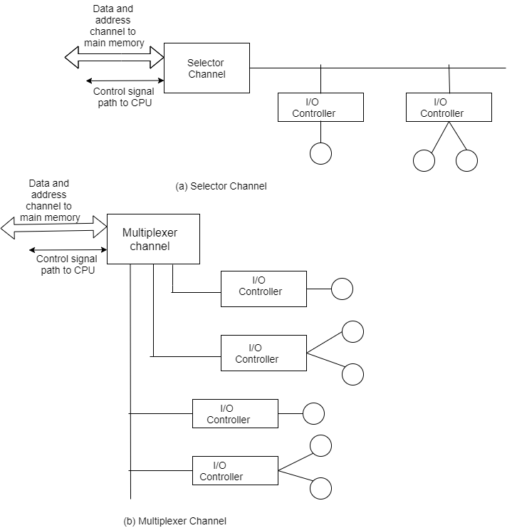
A selector channel controls multiple high-speed devices and at any one time is dedicated to transfer of data with one of those devices. Every device is handled by a controller or I/O interface. So I/O channel serves in place of CPU in controlling these I/O controllers.
A multiplexer channel can handle I/O with many devices at the same time. If devices are slow then byte multiplexer is used. Let's explain this with illustration. If we have 3 slow devices that need to send individual bytes as:
X1 X2 X3 X4 X5 ......
Y1 Y2 Y3 Y4 Y5......
Z1 Z2 Z3 Z4 Z5......
Then on a byte multiplexer channel they can transmit bytes as X1 Y1 Z1 X2 Y2 Z2 X3 Y3 Z3...... For high-speed devices blocks of data from various devices are interleaved. These devices are known as block multiplexer.
Input-output processor:
The DMA mode of data transfer reduces CPU’s overhead in handling I/O operations. It also allows parallelism in CPU and I/O operations. Such parallelism is necessary to avoid wastage of valuable CPU time while handling I/O devices whose speeds are much slower as compared to CPU. The concept of DMA operation can be extended to relieve the CPU further from getting involved with the execution of I/O operations. This gives rises to the development of special purpose processor called Input-Output Processor (IOP) or IO channel. The Input Output Processor (IOP) is just like a CPU that handles the details of I/O operations. It is more equipped with facilities than those are available in typical DMA controller. The IOP can fetch and execute its own instructions that are specifically designed to characterize I/O transfers. In addition to the I/O – related tasks, it can perform other processing tasks like arithmetic, logic, branching and code translation. The main memory unit takes the pivotal role. It communicates with processor by the means of DMA.
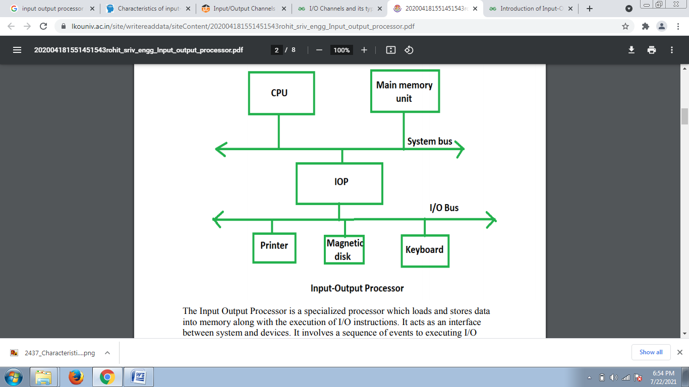
The Input Output Processor is a specialized processor which loads and stores data into memory along with the execution of I/O instructions. It acts as an interface between system and devices. It involves a sequence of events to executing I/O operations and then store the results into the memory.
Advantages:
The I/O devices can directly access the main memory without the intervention by the processor in I/O processor based systems.
It is used to address the problems that are arises in Direct memory access method
What is Transmission:
Transmission is the action of transferring or moving something from one position or person to another. It is a mechanism of transferring data between two devices connected using a network. It is also called communication Mode.
Two types of Transmission:
- Synchronous
- Asynchronous transmissions
Synchronous Transmission:
- Synchronous data transmission is a data transfer method in which is a continuous stream of data signals accompanied by timing signals. It helps to ensure that the transmitter and the receiver are synchronized with each other.
- This communication methods is mostly used when large amounts of data needs to be transferred from one location to the other.

Asynchronous Transmission:
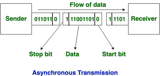
Asynchronous Transmission is also known as start/stop transmission, sends data from the sender to the receiver using the flow control method. It does not use a clock to synchronize data between the source and destination.
This transmission method sends one character or 8 bits at a time. In this method, before the transmission process begins, each character sends the start bit. After sending the character, it also sends the stop bit. With the character bits and start and stop bits, the total number of bits is 10 bits.
KEY DIFFERENCES:
- Synchronous is a data transfer method in which a continuous stream of data signals is accompanied by timing signals whereas Asynchronous data transmission is a data transfer method in which the sender and the receiver use the flow control method.
- In, synchronous transmission method users need to wait until it sending finishes before getting a response from the server. On the contrary, Asynchronous transmission method users do not have to wait until sending completes before receiving a response from the server.
- Synchronous Transmission sends data in the form of blocks or frames while Asynchronous Transmission send data in the form of character or byte.
- Synchronous Transmission is fast. On the other hand, Asynchronous transmission method is slow.
- Synchronous Transmission is costly whereas Asynchronous Transmission is economical.
How Synchronous Transmission works:
- Separate clocking lines used when the distance between the data terminal equipment (DTE) and data communications equipment (DCE) is short.
- This method uses a clocking electrical system at both transmitting and receiving stations. This ensures that the communication process is synchronized.
- Devices that communicate with each other Synchronously use either separate clocking channels.
How Asynchronous Transmission works:
- Asynchronous communication is eased by two bits, which is known as start bit as '0' and stop bit as '1.'
- You need to send '0' bit to start the communication & '1' bit to stop the Transmission.
- There is a time delay between the communication of two bytes.
- The transmitter and receiver may be function at different clock frequencies.
Advantages of Synchronous Transmission
- It helps you to transfer a large amount of data.
- It offers real-time communication between connected devices.
- Each byte is transmitted without a gap between the next byte.
- It also reduces time timing errors.
Advantages of Asynchronous Transmission
- This is a highly flexible method of data transmission.
- Synchronization between the receiver and transmitter is unnecessary.
- It helps you to transmit signals from the sources which have different bit rates.
- The Transmission can resume as soon as the data byte transmission is available.
- This mode of Transmission is easy for implementation.
Disadvantages of Asynchronous Transmission
- In Asynchronous Transmission, additional bits called start and stop bits are required to be used.
- The timing error may take place as it is difficult to determine synchronicity.
- It has a slower transmission rate.
- May create false recognition of these bits because of noise on the channel.
Disadvantages of Synchronous Transmission.
- The accuracy of the received data depends on the receiver's ability to count the received bits accurately.
- The transmitter and receiver need to operate simultaneously with the same clock frequency.
The processor bus is the bus defied by the signals on the processor chip itself. Devices that require a very high-speed connection to the processor, such as the main memory, may be connected directly to this bus. For electrical reasons, only a few devices can be connected in this manner. The motherboard usually provides another bus that can support more devices.
The two buses are interconnected by a circuit, which we will call a bridge, that translates the signals and protocols of one bus into those of the other. Devices connected to the expansion bus appear to the processor as if they were connected directly to the processor’s own bus.
The only difference is that the bridge circuit introduces a small delay in data transfers between the processor and those devices. It is not possible to define a uniform standard for the processor bus.
The structure of this bus is closely tied to the architecture of the processor. It is also dependent on the electrical characteristics of the processor chip, such as its clock speed.
The expansion bus is not subject to these limitations, and therefore it can use a standardized signaling scheme.
A number of standards have been developed. Some have evolved by default, when a particular design became commercially successful.
For example, IBM developed a bus they called ISA (Industry Standard Architecture) for their personal computer known at the time as PC AT.
Some standards have been developed through industrial cooperative efforts, even among competing companies driven by their common self-interest in having compatible products.
In some cases, organizations such as the IEEE (Institute of Electrical and Electronics Engineers), ANSI (American National Standards Institute), or international bodies such as ISO (International Standards Organization) have blessed these standards and given them an official status. A given computer may use more than one bus standards. A typical Pentium computer has both a PCI bus and an ISA bus, thus providing the user with a wide range of devices to choose from.
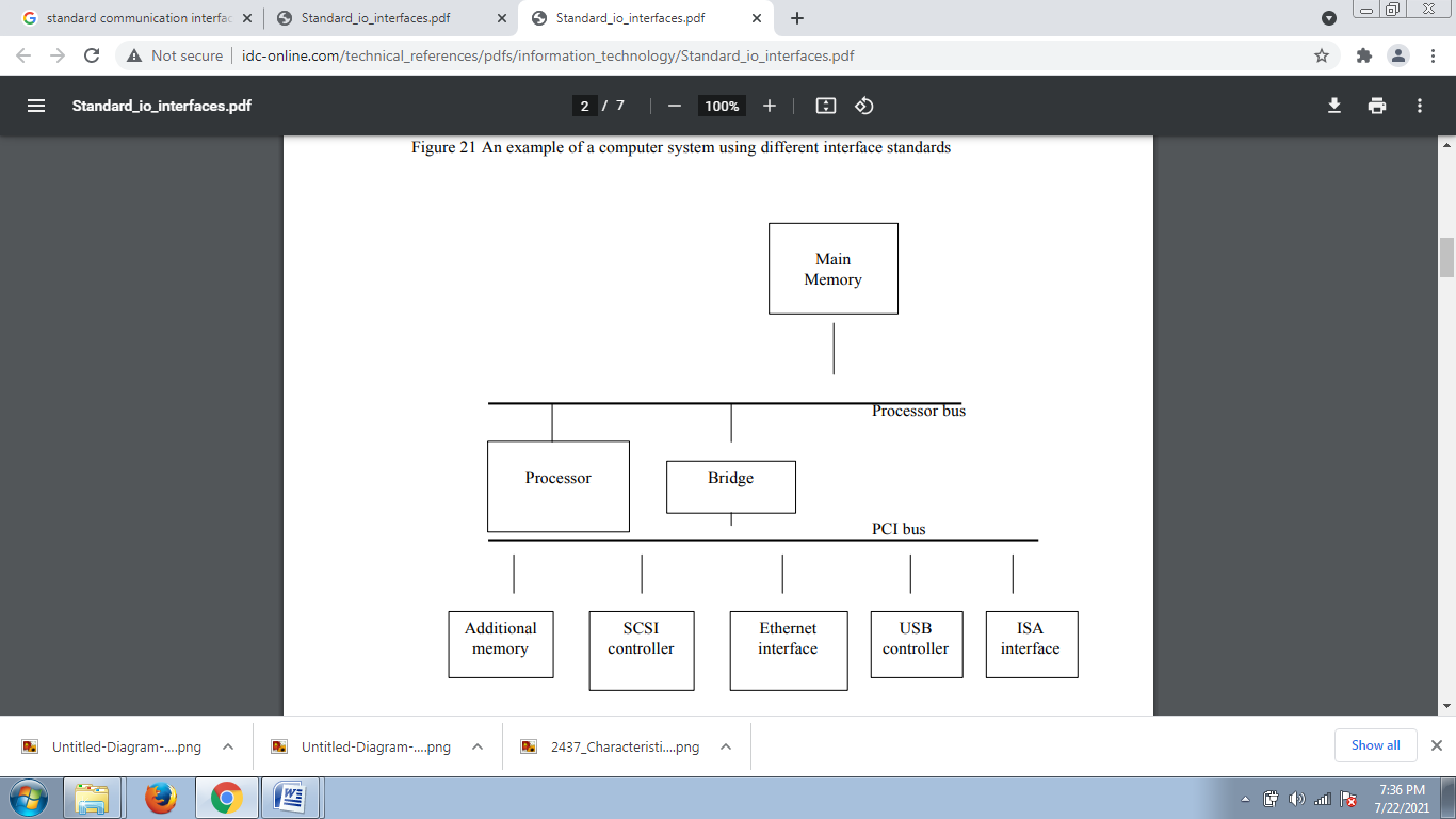
Fig-An example of a computer system using different interface standards
Peripheral Component Interconnect (PCI) Bus:
The PCI bus is a good example of a system bus that grew out of the need for standardization. It supports the functions found on a processor bus bit in a standardized format that is independent of any particular processor.
Devices connected to the PCI bus appear to the processor as if they were connected directly to the processor bus. They are assigned addresses in the memory address space of the processor.
The PCI follows a sequence of bus standards that were used primarily in IBM PCs. Early PCs used the 8-bit XT bus, whose signals closely mimicked those of Intel’s 80x86 processors. Later, the 16-bit bus used on the PC At computers became known as the ISA bus. Its extended 32-bit version is known as the EISA bus.
Other buses developed in the eighties with similar capabilities are the Microchannel used in IBM PCs and the NuBus used in Macintosh computers.
The PCI was developed as a low-cost bus that is truly processor independent. Its design anticipated a rapidly growing demand for bus bandwidth to support high-speed disks and graphic and video devices, as well as the specialized needs of multiprocessor systems.
As a result, the PCI is still popular as an industry standard almost a decade after it was first introduced in 1992. An important feature that the PCI pioneered is a plug-and-play capability for connecting I/O devices. To connect a new device, the user simply connects the device interface board to the bus. The software takes care of the rest.
SCSI Bus:
The acronym SCSI stands for Small Computer System Interface. It refers to a standard bus defined by the American National Standards Institute (ANSI) under the designation X3.131.
In the original specifications of the standard, devices such as disks are connected to a computer via a 50-wire cable, which can be up to 25 meters in length and can transfer data at rates up to 5 megabytes/s.
The SCSI bus standard has undergone many revisions, and its data transfer capability has increased very rapidly, almost doubling every two years. SCSI-2 and SCSI-3 have been defined, and each has several options.
A SCSI bus may have eight data lines, in which case it is called a narrow bus and transfers data one byte at a time. Alternatively, a wide SCSI bus has 16 data lines and transfers data 16 bits at a time.
There are also several options for the electrical signaling scheme used. Devices connected to the SCSI bus are not part of the address space of the processor in the same way as devices connected to the processor bus.
The SCSI bus is connected to the processor bus through a SCSI controller. This controller uses DMA to transfer data packets from the main memory to the device, or vice versa.
A packet may contain a block of data, commands from the processor to the device, or status information about the device. To illustrate the operation of the SCSI bus, let us consider how it may be used with a disk drive.
Communication with a disk drive differs substantially from communication with the main memory. A controller connected to a SCSI bus is one of two types – an initiator or a target. An initiator has the ability to select a particular target and to send commands specifying the operations to be performed.
Clearly, the controller on the processor side, such as the SCSI controller, must be able to operate as an initiator. The disk controller operates as a target. It carries out the commands it receives from the initiator.
The initiator establishes a logical connection with the intended target. Once this connection has been established, it can be suspended and restored as needed to transfer commands and bursts of data. While a particular connection is suspended, other device can use the bus to transfer information.
This ability to overlap data transfer requests is one of the key features of the SCSI bus that leads to its high performance. Data transfers on the SCSI bus are always controlled by the target controller.
To send a command to a target, an initiator requests control of the bus and, after winning arbitration, selects the controller it wants to communicate with and hands control of the bus over to it. Then the controller starts a data transfer operation to receive a command from the initiator.
The processor sends a command to the SCSI controller, which causes the following sequence of event to take place:
1. The SCSI controller, acting as an initiator, contends for control of the bus.
2. When the initiator wins the arbitration process, it selects the target controller and hands over control of the bus to it.
3. The target starts an output operation (from initiator to target); in response to this, the initiator sends a command specifying the required read operation.
4. The target, realizing that it first needs to perform a disk seek operation, sends a message to the initiator indicating that it will temporarily suspend the connection between them. Then it releases the bus.
5. The target controller sends a command to the disk drive to move the read head to the first sector involved in the requested read operation. Then, it reads the data stored in that sector and stores them in a data buffer. When it is ready to begin transferring data to the initiator, the target requests control of the bus. After it wins arbitration, it reselects the initiator controller, thus restoring the suspended connection.
6. The target transfers the contents of the data buffer to the initiator and then suspends the connection again. Data are transferred either 8 or 16 bits in parallel, depending on the width of the bus.
7. The target controller sends a command to the disk drive to perform another seek operation. Then, it transfers the contents of the second disk sector to the initiator as before. At the end of this transfers, the logical connection between the two controllers is terminated.
8. As the initiator controller receives the data, it stores them into the main memory using the DMA approach. 9. The SCSI controller sends as interrupt to the processor to inform it that the requested operation has been completed
References:
1. Computer System Architecture - M. Mano
2. Carl Hamacher, Zvonko Vranesic, Safwat Zaky Computer Organization, McGraw-Hill, Fifth Edition, Reprint 2012
3. John P. Hayes, Computer Architecture and Organization, Tata McGraw Hill, Third Edition, 1998. Reference books
4. William Stallings, Computer Organization and Architecture-Designing for Performance, Pearson Education, Seventh edition, 2006.
5. Behrooz Parahami, “Computer Architecture”, Oxford University Press, Eighth Impression, 2011.