UNIT 3
CPU Scheduling
Method hardware schedules completely different processes to be appointed to the computer hardware supported specific programming algorithms. There square measure six well-liked method programming algorithms that we tend to square measure attending to discuss during this during this
• First-Come, First-Served (FCFS) programing
• Shortest-Job-Next (SJN) programing
• Priority programing
• Shortest Remaining Time
• Round Robin(RR) programing
• Multiple-Level Queues programing
These algorithms square measure either non-preemptive or preventive. A non-preemptive algorithms square measure designed so that once a method enters the running state, it can not be preempted till it completes its assigned time, whereas the preventive programming relies on priority where hardware could preempt a coffee priority running method any-time once a high priority method enters into a prepared state.
First Come First Serve (FCFS)
- Jobs are executed on a first-come, first-serve basis.
- It is a non-preemptive, pre-emptive scheduling algorithm.
- Easy to understand and implement.
- Its implementation is based on the FIFO queue.
- Poor in performance as the average wait time is high.
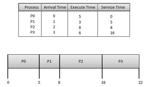
The wait time of each process is as follows −
Process | Wait Time: Service Time - Arrival Time |
P0 | 0 - 0 = 0 |
P1 | 5 - 1 = 4 |
P2 | 8 - 2 = 6 |
P3 | 16 - 3 = 13 |
Average Wait Time: (0+4+6+13) / 4 = 5.75
Shortest Job Next (SJN)
- This is also known as the shortest job first, or SJF
- This is a non-preemptive, pre-emptive scheduling algorithm.
- The best approach to minimize waiting time.
- Easy to implement in Batch systems where required CPU time is known in advance.
- Impossible to implement in interactive systems where required CPU time is not known.
- The processer should know in advance how much time the process will take.
Given: Table of processes, and their Arrival time, Execution time
Process | Arrival Time | Execution Time | Service Time |
P0 | 0 | 5 | 0 |
P1 | 1 | 3 | 5 |
P2 | 2 | 8 | 14 |
P3 | 3 | 6 | 8 |

The waiting time of each process is as follows −
Process | Waiting Time |
P0 | 0 - 0 = 0 |
P1 | 5 - 1 = 4 |
P2 | 14 - 2 = 12 |
P3 | 8 - 3 = 5 |
Average Wait Time: (0 + 4 + 12 + 5)/4 = 21 / 4 = 5.25
Priority Based Scheduling
- Priority scheduling is a non-preemptive algorithm and one of the most common scheduling algorithms in batch systems.
- Each process is assigned a priority. The process with the highest priority is to be executed first and so on.
- Processes with the same priority are executed on a first-come-first-served basis.
- Priority can be decided based on memory requirements, time requirements, or any other resource requirement.
Given: Table of processes, and their Arrival time, Execution time, and priority. Here we are considering 1 is the lowest priority.
Process | Arrival Time | Execution Time | Priority | Service Time |
P0 | 0 | 5 | 1 | 0 |
P1 | 1 | 3 | 2 | 11 |
P2 | 2 | 8 | 1 | 14 |
P3 | 3 | 6 | 3 | 5 |

The waiting time of each process is as follows −
Process | Waiting Time |
P0 | 0 - 0 = 0 |
P1 | 11 - 1 = 10 |
P2 | 14 - 2 = 12 |
P3 | 5 - 3 = 2 |
Average Wait Time: (0 + 10 + 12 + 2)/4 = 24 / 4 = 6
Shortest Remaining Time
- The shortest remaining time (SRT) is the preemptive version of the SJN algorithm.
- The processor is allocated to the job closest to completion but it can be preempted by a newer ready job with a shorter time to completion.
- Impossible to implement in interactive systems where required CPU time is not known.
- It is often used in batch environments where short jobs need to give preference.
Round Robin Scheduling
- Round Robin is the preemptive process scheduling algorithm.
- Each process is provided a fixed time to execute, it is called a quantum.
- Once a process is executed for a given period, it is preempted and another process executes for a given period.
- Context switching is used to save states of preempted processes.
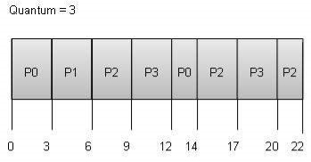
The wait time of each process is as follows −
Process | Wait Time: Service Time - Arrival Time |
P0 | (0 - 0) + (12 - 3) = 9 |
P1 | (3 - 1) = 2 |
P2 | (6 - 2) + (14 - 9) + (20 - 17) = 12 |
P3 | (9 - 3) + (17 - 12) = 11 |
Average Wait Time: (9+2+12+11) / 4 = 8.5
Multiple-Level Queues Scheduling
Multiple-level queues are not an independent scheduling algorithm. They make use of other existing algorithms for the group and schedule jobs with common characteristics.
- Multiple queues are maintained for processes with common characteristics.
- Each queue can have its scheduling algorithms.
- Priorities are assigned to each queue.
For example, CPU-bound jobs can be scheduled in one queue and all I/O-bound jobs in another queue. The Process Scheduler then alternately selects jobs from each queue and assigns them to the CPU based on the algorithm assigned to the queue.
KEY TAKEAWAY
Method hardware schedules completely different processes to be appointed to the computer hardware supported specific programming algorithms. There square measure six well-liked method programming algorithms that we tend to square measure attending to discuss during this during this
• First-Come, First-Served (FCFS) programing
• Shortest-Job-Next (SJN) programing
• Priority programing
• Shortest Remaining Time
• Round Robin(RR) programing
• Multiple-Level Queues programming
Different computer hardware programming rules have completely different properties and also the selection of a selected algorithm depends on the varied factors. Several criteria are recommended for the examination of computer hardware programming algorithms.
The criteria embrace the following:
1. Computer hardware utilization –
The main objective of any computer hardware programming rule is to stay the computer hardware as busy as doable. In theory, computer hardware utilization will vary from zero to a hundred however during a period system, it varies from forty to ninety p.c counting on the load upon the system.
2. Output –
The live of the work done by computer hardware is that the range of processes being dead and completed per unit time. This can be referred to as output. The output could vary relying upon the length or period of processes.
3. Work time –
For a selected method, a crucial criterion is however long it takes to execute that method. The time marches on from the time of submission of a method to the time of completion is thought of because of the work time. Turn-around time is that the addition of times spent waiting to urge into memory, waiting in the prepared queue, capital punishment in computer hardware, and looking forward to I/O.
4. Waiting time –
A programming rule doesn't affect the time needed to complete the process once it starts execution. It solely affects the waiting time of a method i.e. time spent by a method waiting within the prepared queue.
5. Time interval –
In the Associate in Nursing interactive system, turn-around time isn't the most effective criteria. A method could turn out some output fairly early and continue computing new results whereas previous results area unit being output to the user. Therefore another criterion is that the time taken from submission of the method of request till the primary response is created. This live is termed time interval.
There area unit numerous computer hardware programming algorithms such as as-
• 1st return First Served (FCFS)
• Shortest Job 1st (SJF)
• Longest Job 1st (LJF)
• Priority programming
• Round Robin (RR)
• Shortest Remaining Time 1st (SRTF)
• Longest Remaining Time 1st (LRTF)
KEY TAKEAWAY
Different computer hardware programming rules have completely different properties and also the selection of a selected algorithm depends on the varied factors. Several criteria are recommended for the examination of computer hardware programming algorithms.
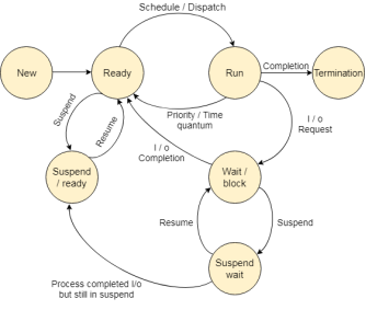
Fig 1 – State Diagram
The method, from its creation to completion, passes through numerous states. The minimum range of states is 5.
The names of the states don't seem to be standardized though the method is also in one in all the subsequent states throughout execution.
1. New
A program that goes to be picked up by the OS into the most memory is termed a replacement method.
2. Ready
Whenever a method is made, it directly enters within the prepared state, in which, it waits for the mainframe to be appointed. The OS picks the new processes from the secondary memory and places all of them within the main memory.
The processes that are prepared for the execution and reside within the main memory are referred to as prepared state processes. There are often several processes gift within the prepared state.
3. Running
One of the processes from the prepared state is going to be chosen by the OS relying upon the programming algorithmic rule. Hence, if we've got only 1 mainframe in our system, the quantity of running processes for a specific time can continuously be one. If we've got n processors within the system then we will have n processes running at the same time.
4. Block or wait
From the Running state, a method will build the transition to the block or wait state relying upon the programming algorithmic rule or the intrinsic behavior of the method.
When a method waits for a definite resource to be appointed or for the input from the user then the OS move this method to the block or waits for state and assigns the mainframe to the opposite processes.
5. Completion or termination
When a method finishes its execution, it comes within the termination state. All the context of the method (Process management Block) will be deleted the method is going to be terminated by the software.
6. Suspend prepared
A method within the prepared state, that is enraptured to secondary memory from the most memorable thanks to lack of the resources (mainly primary memory) is termed within the suspend prepared state.
If the most memory is full and the next priority method comes for the execution then the OS need to build the area for {the method|the method} within the main memory by throwing the lower priority process out into the secondary memory. The suspend prepared processes stay within the secondary memory till the most memory gets accessible.
7. Suspend wait
Instead of removing the method from the prepared queue, it's higher to get rid of the blocked method that is watching for some resources within the main memory. Since it's already watching for some resource to urge accessible thus it's higher if it waits within the secondary memory and creates space for the upper priority method. These processes complete their execution once the most memory gets accessible and their wait is finished.
Operations on the method
1. Creation
Once the method is made, it'll be prepared and are available in the prepared queue (main memory) and can be prepared for execution.
2. Scheduling
Out of the various processes gift within the prepared queue, the software chooses one method and begins executing it. Choosing the method that is to be dead next, is understood as programing.
3. Execution
Once the method is regular for the execution, the processor starts executing it. The method could come back to the blocked or wait for the state throughout the execution then therein case the processor starts execution the opposite processes.
4. Deletion/killing
Once the aim of the method gets over then the OS can kill the method. The context of{the method (PCB) are going to be deleted and also the process gets terminated by the software.
KEY TAKEAWAY
The method, from its creation to completion, passes through numerous states. The minimum range of states is 5.
The names of the states don't seem to be standardized though the method is also in one in all the subsequent states throughout execution.
Process
A method is essentially a program in execution. The execution of a method should progress in an exceedingly consecutive fashion.
A method is outlined as an Associate in Nursing entity that represents the essential unit of labor to be enforced within the system.
To put it in easy terms, we tend to write our laptop programs in an exceedingly computer file and after we execute this program, it becomes a method that performs all the tasks mentioned within the program.
When a program is loaded into the memory and it becomes a method, it is divided into four sections ─ stack, heap, text, and information. The subsequent image shows a simplified layout of a method within main memory −
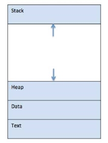
Fig 2 – memory
S.N. | Component & Description |
1 | Stack The process Stack contains temporary data such as method/function parameters, return address, and local variables. |
2 | Heap This is dynamically allocated memory to a process during its run time. |
3 | Text This includes the current activity represented by the value of the Program Counter and the contents of the processor's registers. |
4 | Data This section contains global and static variables. |
Program
A program is a piece of code that may be a single line or millions of lines. A computer program is usually written by a computer programmer in a programming language. For example, here is a simple program that is written in C programming language −
#include <stdio.h>
Int main() {
Printf("Hello, World! \n");
Return 0;
}
A computer program is a collection of instructions that performs a specific task when executed by a computer. When we compare a program with a process, we can conclude that a process is a dynamic instance of a computer program.
A part of a computer program that performs a well-defined task is known as an algorithm. A collection of computer programs, libraries, and related data are referred to as software.
Process Life Cycle
When a process executes, it passes through different states. These stages may differ in different operating systems, and the names of these states are also not standardized.
In general, a process can have one of the following five states at a time.
S.N. | State & Description |
1 | Start This is the initial state when a process is first started/created. |
2 | Ready The process is waiting to be assigned to a processor. Ready processes are waiting to have the processor allocated to them by the operating system so that they can run. The process may come into this state after Start state or while running it by but interrupted by the scheduler to assign CPU to some other process. |
3 | Running Once the process has been assigned to a processor by the OS scheduler, the process state is set to running and the processor executes its instructions. |
4 | Waiting The process moves into the waiting state if it needs to wait for a resource, such as waiting for user input, or waiting for a file to become available. |
5 | Terminated or Exit Once the process finishes its execution, or it is terminated by the operating system, it is moved to the terminated state where it waits to be removed from the main memory. |
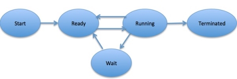
Fig 3 – Process state
Process Control Block (PCB)
A Process Control Block is a data structure maintained by the Operating System for every process. The PCB is identified by an integer process ID (PID). A PCB keeps all the information needed to keep track of a process as listed below in the table −
S.N. | Information & Description |
1 | Process State The current state of the process i.e., whether it is ready, running, waiting, or whatever. |
2 | Process privileges This is required to allow/disallow access to system resources. |
3 | Process ID Unique identification for each of the processes in the operating system. |
4 | Pointer A pointer to the parent process. |
5 | Program Counter Program Counter is a pointer to the address of the next instruction to be executed for this process. |
6 | CPU registers Various CPU registers where processes need to be stored for execution for running state. |
7 | CPU Scheduling Information Process priority and other scheduling information that is required to schedule the process. |
8 | Memory management information This includes the information of the page table, memory limits, Segment table depending on the memory used by the operating system. |
9 | Accounting information This includes the amount of CPU used for process execution, time limits, execution ID, etc. |
10 | IO status information This includes a list of I/O devices allocated to the process. |
The architecture of a PCB is completely dependent on Operating System and may contain different information in different operating systems. Here is a simplified diagram of a PCB −
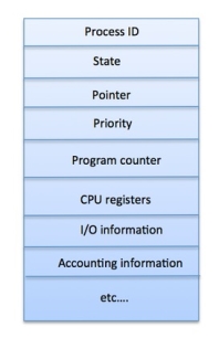
Fig 4 – PCB
The PCB is maintained for a process throughout its lifetime and is deleted once the process terminates.
KEY TAKEAWAY
Process
A method is essentially a program in execution. The execution of a method should progress in an exceedingly consecutive fashion.
A method is outlined as an Associate in Nursing entity that represents the essential unit of labor to be enforced within the system.
To put it in easy terms, we tend to write our laptop programs in an exceedingly computer file and after we execute this program, it becomes a method that performs all the tasks mentioned within the program.
Process Schedulers
The operating system uses numerous schedulers for the method programming delineate be-low.
1. Long-run computer hardware
Long term computer hardware is additionally called job computer hardware. It chooses the processes from the pool (secondary memory) and keeps them within the prepared queue maintained within the primary memory.
Long Term computer hardware in the main controls the degree of concurrent execution. Long-run computer hardware aims to settle on an ideal mixture of IO sure and processor sure processes among the roles gift within the pool.
If the work computer hardware chooses additional IO sure processes then all of the roles might reside within the blocked state all the time and also the processor can stay idle most of the time. This may scale back the degree of concurrent execution. Therefore, the work of long-run computer hardware is incredibly essential and will have an effect on the system for a real while.
2. Short term computer hardware
Short term computer hardware is additionally called processor computer hardware. It selects one in all the roles from the prepared queue and dispatch to the processor for execution.
A programming algorithmic rule is employed to pick out that job goes to be sent for execution. The work of the short-term computer hardware is often terribly essential within the sense that if it selects a job whose processor burst time is incredibly high then all the roles subsequently, can be got to wait within the prepared queue for a real while.
This drawback is named starvation which can arise if the short term computer hardware makes some mistakes whereas choosing the work.
3. Medium-term computer hardware
Medium-term computer hardware takes care of the swapped out processes. If the running state processes want some IO time for the completion then there's a desire to alter its state from running to waiting.
Medium-term computer hardware is employed for this purpose. It removes the method from the running state to create an area for the opposite processes. Such processes area unit the swapped out processes and this procedure is named swapping. The medium-term computer hardware is responsible for suspending and resuming the processes.
It reduces the degree of concurrent execution. The swapping is important to own an ideal mixture of processes within the prepared queue.
KEY TAKEAWAY
Process Schedulers
The operating system uses numerous schedulers for the method programming delineate be-low.
1. Long-run computer hardware
Long term computer hardware is additionally called job computer hardware. It chooses the processes from the pool (secondary memory) and keeps them within the prepared queue maintained within the primary memory.
Long Term computer hardware in the main controls the degree of concurrent execution. Long-run computer hardware aims to settle on an ideal mixture of IO sure and processor sure processes among the roles gift within the pool.
Process management Block could be an organization that contains data of the method related thereto. The method management block is additionally called a task management block, entry of the method table, etc.
It is vital for method management because the knowledge structuring for processes is finished in terms of the PCB. It additionally defines this state of the OS.
Structure of the method management Block
The method management stores several knowledge things that area unit required for economical process management. a number of these knowledge things area unit explained with the assistance of the given diagram −
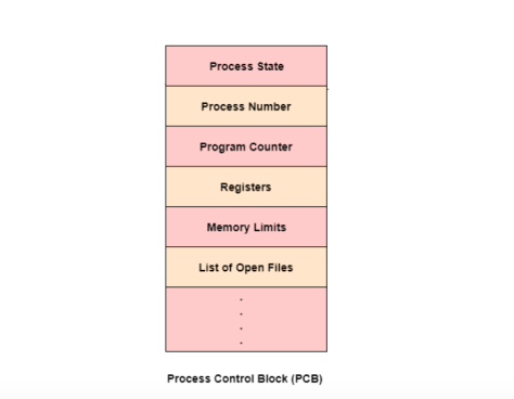
FIG 5 – Process control block
The following area unit the info the info
Process State
This specifies the method state i.e. new, ready, running, waiting, or terminated.
Process range
This shows the quantity of the actual method.
Program Counter
This contains the address of consecutive instruction that has to be dead within the process.
Registers
This specifies the registers that area unit utilized by the method. They will embrace accumulators, index registers, stack pointers, general-purpose registers, etc.
List of Open Files
This area unit the various files that area unit related to the method
CPU programming data
The process priority, tips that could programming queues, etc. is that the CPU programming information that's contained within the PCB. This might additionally embrace the other programming parameters.
Memory Management data
The memory management data includes the page tables or the section tables counting on the memory system used. It additionally contains the worth of the bottom registers, limit registers, etc.
I/O standing data
This data includes the list of I/O devices utilized by the method, the list of files, etc.
Accounting data
The deadlines, account numbers, quantity of CPU used, method numbers, etc. area unit all an area of the PCB accounting data.
Location of the method management Block
The process management block is unbroken during a memory space that's shielded from the traditional user access. This can be done as a result of it contains necessary method data. a number of the operating systems place the PCB at the start of the kernel stack for the process because it could be a safe location.
KEY TAKEAWAY
Process management Block could be an organization that contains data of the method related thereto. The method management block is additionally called a task management block, entry of the method table, etc.
It is vital for method management because the knowledge structuring for processes is finished in terms of the PCB. It additionally defines this state of the OS.
Memory management is that the practicality of AN OS that handles or manages primary memory and moves processes back and forth between main memory and disk throughout execution. Memory management keeps track of every memory location, no matter either it's allotted to some method or it's free. It checks what quantity memory is to be allotted to processes. It decides that method can get memory at what time. It tracks whenever some memory gets freed or unallocated and correspondingly it updates the standing.
This tutorial can teach you basic ideas associated with Memory Management.
Process Address house
The method address house is the set of logical addresses that a process references in its code. As an example, once 32-bit addressing is in use, addresses will vary from zero to 0x7fffffff; that's, 2^31 doable numbers, for a complete theoretical size of two gigabytes.
The OS takes care of mapping the logical addresses to physical addresses at the time of memory allocation to the program. There area unit 3 styles of ad-dresses employed in a program before and when memory is allotted allotted
S.N. Memory Addresses & Description
1 Symbolic addresses
The addresses are employed in an ASCII text file. The variable names, constants, and instruction labels area unit the fundamental parts of the symbolic address house.
2 Relative addresses
At the time of compilation, a compiler converts symbolic addresses into relative addresses.
3 Physical addresses
The loader generates these addresses at the time once a program is loaded into main memory.
Virtual and physical addresses area unit constant in compile-time and load-time address-binding schemes. Virtual and physical addresses dissent in execution-time address-binding theme.
The set of all logical addresses generated by a program is cited as a logical address house. The set of all physical addresses resembling these logical addresses is cited as a physical address house.
The runtime mapping from virtual to physical address is completed by the memory management unit (MMU) that could be a hardware device. MMU uses the following mechanism to convert virtual addresses to a physical addresses.
• The worth within the base register is else to each address generated by a user method, that is treated as an offset at the time it's sent to memory. As an example, if the bottom register worth is ten thousand, then an effort by the user to use address location a hundred are dynamically reallocated to location 10100.
• The user program deals with virtual addresses; it ne'er sees the $64000 physical addresses.
Static vs Dynamic Loading
The choice between Static or Dynamic Loading is to be created at the time of the computer virus being developed. If you have got to load your program statically, then at the time of compilation, the entire programs are compiled and connected while not deed any external program or module dependency. The linker combines the thing program with alternative necessary object modules into AN absolute program, that additionally includes logical addresses.
If you're writing a Dynamically loaded program, then your compiler can compile the program and for all the modules that you wish to incorporate dynamically, solely references are provided and the remainder of the work is done at the time of execution.
At the time of loading, with static loading, absolutely the program (and data) is loaded into memory so as for execution to begin.
If you're exploiting dynamic loading, dynamic routines of the library area unit hold on on a disk in relocatable type and area unit loaded into memory only they're required by the program.
Static vs Dynamic Linking
As explained higher than, once static linking is employed, the linker combines all alternative modules required by a program into one feasible program to avoid any runtime dependency.
When dynamic linking is employed, it's not needed to link the particular module or library with the program, rather respect to the dynamic module is provided at the time of compilation and linking. Dynamic Link Libraries (DLL) in Windows and Shared Objects in OS area unit smart samples of dynamic libraries.
Swapping
Swapping could be a mechanism within which a method may be swapped briefly out of main memory (or move) to external storage (disk) and create that memory offered to alternative processes. At some later time, the system swaps back the method from the secondary storage to main memory.
Though performance is sometimes tormented by the swapping method however it helps in running multiple and massive processes in parallel and that is the explanation Swapping is additionally referred to as a method for memory compaction.
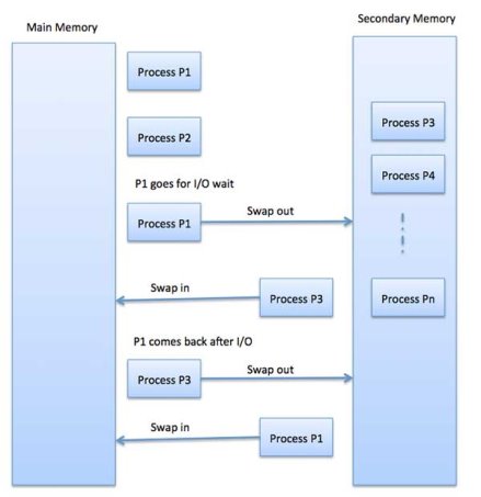
Fig 6 – Example
The total time taken by the swapping process includes the time it takes to move the entire process to a secondary disk and then to copy the process back to memory, as well as the time the process takes to regain main memory.
Let us assume that the user process is of size 2048KB and on a standard hard disk where swapping will take place has a data transfer rate around 1 MB per second. The actual transfer of the 1000K process to or from memory will take
2048KB / 1024KB per second
= 2 seconds
= 2000 milliseconds
Now considering in and out time, it will take complete 4000 milliseconds plus other overhead where the process competes to regain main memory.
Memory Allocation
Main memory usually has two partitions −
- Low Memory − Operating system resides in this memory.
- High Memory − User processes are held in high memory.
The operating system uses the following memory allocation mechanism.
S.N. | Memory Allocation & Description |
1 | Single-partition allocation In this type of allocation, a relocation-register scheme is used to protect user processes from each other, and from changing operating-system code and data. The relocation register contains the value of the smallest physical address whereas the limit register contains a range of logical addresses. Each logical address must be less than the limit register. |
2 | Multiple-partition allocation In this type of allocation, the main memory is divided into several fixed-sized partitions where each partition should contain only one process. When a partition is free, a process is selected from the input queue and is loaded into the free partition. When the process terminates, the partition becomes available for another process. |
Fragmentation
As processes are loaded and removed from memory, the free memory space is broken into little pieces. It happens after some time that processes cannot be allocated to memory blocks considering their small size and memory blocks remains unused. This problem is known as Fragmentation.
Fragmentation is of two types −
S.N. | Fragmentation & Description |
1 | External fragmentation Total memory space is enough to satisfy a request or to reside a process in it, but it is not contiguous, so it cannot be used. |
2 | Internal fragmentation The memory block assigned to the process is bigger. Some portion of memory is left unused, as it cannot be used by another process. |
The following diagram shows how fragmentation can cause waste of memory and a compaction technique can be used to create more free memory out of fragmented memory −
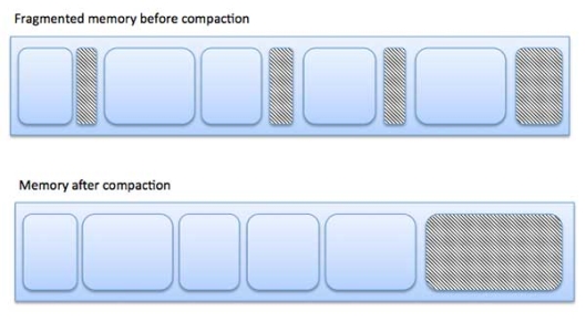
Fig 7 – Fragmentation
External fragmentation can be reduced by compaction or shuffle memory contents to place all free memory together in one large block. To make compaction feasible, relocation should be dynamic.
The internal fragmentation can be reduced by effectively assigning the smallest partition but large enough for the process.
Paging
A computer can address more memory than the amount physically installed on the system. This extra memory is called virtual memory and it is a section of a hard that's set up to emulate the computer's RAM. The paging technique plays an important role in implementing virtual memory.
Paging is a memory management technique in which process address space is broken into blocks of the same size called pages (size is the power of 2, between 512 bytes and 8192 bytes). The size of the process is measured in the number of pages.
Similarly, main memory is divided into small fixed-sized blocks of (physical) memory called frames and the size of a frame is kept the same as that of a page to have optimum utilization of the main memory and to avoid external fragmentation.
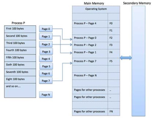
Fig 8 – External fragmentation
Address Translation
The page address is called logical address and is represented by the page number and the offset.
Logical Address = Page number + page offset
The frame address is called a physical address and is represented by a frame number and the offset.
Physical Address = Frame number + page offset
A data structure called a page map table is used to keep track of the relation between a page of a process to a frame in physical memory.
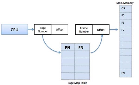
Fig 9 – Map table
When the system allocates a frame to any page, it translates this logical address into a physical address and creates an entry into the page table to be used throughout the execution of the program.
When a process is to be executed, its corresponding pages are loaded into any available memory frames. Suppose you have a program of 8Kb but your memory can accommodate only 5Kb at a given point in time, then the paging concept will come into the picture. When a computer runs out of RAM, the operating system (OS) will move idle or unwanted pages of memory to secondary memory to free up RAM for other processes and brings them back when needed by the program.
This process continues during the whole execution of the program where the OS keeps removing idle pages from the main memory and writes them onto the secondary memory and brings them back when required by the program.
Advantages and Disadvantages of Paging
Here is a list of advantages and disadvantages of paging −
- Paging reduces external fragmentation but still suffers from internal fragmentation.
- Paging is simple to implement and assumed as an efficient memory management technique.
- Due to the equal size of the pages and frames, swapping becomes very easy.
- Page table requires extra memory space, so may not be good for a system having small RAM.
Segmentation
Segmentation is a memory management technique in which each job is divided into several segments of different sizes, one for each module that contains pieces that perform related functions. Each segment is a different logical address space of the program.
When a process is to be executed, its corresponding segmentation is loaded into non-contiguous memory though every segment is loaded into a contiguous block of available memory.
Segmentation memory management works very similar to paging but here segments are of variable-length whereas in paging pages are of fixed size.
A program segment contains the program's main function, utility functions, data structures, and so on. The operating system maintains a segment map table for every process and a list of free memory blocks along with segment numbers, their size, and corresponding memory locations in main memory. For each segment, the table stores the starting address of the segment and the length of the segment. A reference to a memory location includes a value that identifies a segment and an offset.
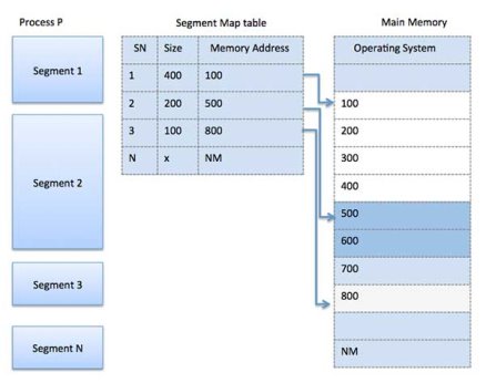
Fig 10 – Segment map table
KEY TAKEAWAY
Memory management is that the practicality of AN OS that handles or manages primary memory and moves processes back and forth between main memory and disk throughout execution. Memory management keeps track of each memory location, no matter either it's allotted to some method or it's free. It checks what quantity memory is to be allotted to processes. It decides that method can get memory at what time. It tracks whenever some memory gets freed or unallocated and correspondingly it updates the standing.
Attributes of a method
The Attributes of the method area unit employed by the software package to form the method management block (PCB) for every one of them. This can be conjointly known as the context of the method. Attributes that area unit hold on within the PCB area unit delineated below.
1. Process ID
When a method is formed, distinctive id is assigned to the method that is employed for unique identification of the method within the system.
2. Program counter
A program counter stores the address of the last instruction of the method on that the method was suspended. The cpu methods unit equipment hardware computer hardware} uses this address once the execution of this process is resumed.
3. Method State
The method, from its creation to the completion, goes through varied states that area unit new, ready, running, and waiting. We'll discuss concerning them later very well.
4. Priority
Every method has its priority. The method with the very best priority among the processes gets the C.P.U. Initial. This can be conjointly held on on the method management block.
5. General-Purpose Registers
Every method has its own set of registers that area unit accustomed to hold the info that is generated throughout the execution of the method.
6. List of open files
During the Execution, each method uses some files which require to be a gift within the main memory. OS conjointly maintains an inventory of open files within the PCB.
7. List of open devices
OS conjointly maintains the list of all open devices that area unit used throughout the execution of the method.
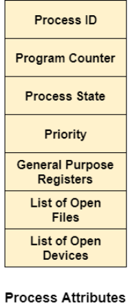
Fig 11 – process attributes
KEY TAKEAWAY
Attributes of a method
The Attributes of the method area unit employed by the software package to form the method management block (PCB) for each of them. This can be conjointly known as the context of the method.
Threads in the software package
There is the simplest way of thread execution within the method of any software package. Except for this, there are often over one thread within a method. Thread is commonly brought up as a light-weight method.
The process is often step-down into such a big amount of threads. For instance, in a very browser, several tabs are often viewed as threads. MS Word uses several threads - format text from one thread, process input from another thread, etc.
Types of Threads
In the software package, there are 2 forms of threads.
1. Kernel level thread.
2. User-level thread.
User-level thread
The software package doesn't acknowledge the user-level thread. User threads are often simply enforced and it's enforced by the user. If a user performs a user-level thread interference operation, the entire method is blocked. The kernel-level thread doesn't unskilled person concerning the user-level thread. The kernel-level thread manages user-level threads as if they're single-threaded processes? examples: Java thread, POSIX threads, etc.
Advantages of User-level threads
1. The user threads are often simply enforced than the kernel thread.
2. User-level threads are often applied to such forms of operational systems that don't support threads at the kernel-level.
3. it's quicker and economical.
4. Context switch time is shorter than the kernel-level threads.
5. It doesn't need modifications to the software package.
6. User-level threads illustration is incredibly easy. The register, PC, stack, and mini thread management blocks are held on within the address house of the user-level method.
7. it's easy to make, switch, and synchronize threads while not the intervention of the method.
Disadvantages of User-level threads
1. User-level threads lack coordination between the thread and also the kernel.
2. If a thread causes a page fault, the complete method is blocked.
Kernel level thread
The kernel thread acknowledges the software package. There are a thread management block and method management block within the system for every thread and method within the kernel-level thread. The kernel-level thread is enforced by the software package. The kernel is aware of concerning all the threads and manages them. The kernel-level thread offers a supervisor call instruction to make and manage the threads from user-space. The implementation of kernel threads is troublesome than the user thread. Context switch time is longer within the kernel thread. If a kernel thread performs an interference operation, the Banky thread execution will continue. Example: Window Solaris.
Advantages of Kernel-level threads
1. The kernel-level thread is responsive to all threads.
2. The computer hardware might conceive to pay a lot of cpu methods unit CPU hardware time within the process of threads being giant numerical.
3. The kernel-level thread is nice for those applications that block the frequency.
Disadvantages of Kernel-level threads
1. The kernel thread manages and schedules all threads.
2. The implementation of kernel threads is troublesome than the user thread.
3. The kernel-level thread is slower than user-level threads.
Components of Threads
Any thread has the subsequent elements.
1. Program counter
2. Register set
3. Stack house
Benefits of Threads
• Enhanced output of the system: once the method is split into several threads, and every thread is treated as employment, the number of jobs worn out the unit time will increase. That's why the output of the system additionally will increase.
• Effective Utilization of a digital computer system: once you have over one thread in one method, you'll be able to schedule over one thread in additional than one processor.
• Faster context switch: The context change amount between threads is a smaller amount than the method context change. The method context switch suggests that a lot of overhead for the computer hardware.
• Responsiveness: once the method is split into many threads, and once a thread completes its execution, that method is often tried and true as presently as attainable.
• Communication: Multiple-thread communication is straightforward as a result of the threads share a similar address house, whereas, in method, we tend to adopt simply a couple of exclusive communication methods for communication between 2 processes.
• Resource sharing: Resources are often shared between all threads inside a process, like code, data, and files. Note: The stack and register can't be shared between threads. There are a stack and register for every thread.
KEY TAKEAWAY
Threads in the software package
There is the simplest way of thread execution within the method of any software package. Except for this, there are often over one thread within a method. Thread is commonly brought up as a light-weight method.
The process is often step-down into such a big amount of threads. For instance, in a very browser, several tabs are often viewed as threads. MS Word uses several threads - format text from one thread, process input from another thread, etc.
A Process Scheduler schedules different processes to be assigned to the CPU based on particular scheduling algorithms. There are six popular process scheduling algorithms which we are going to discuss in this chapter −
- First-Come, First-Served (FCFS) Scheduling
- Shortest-Job-Next (SJN) Scheduling
- Priority Scheduling
- Shortest Remaining Time
- Round Robin(RR) Scheduling
- Multiple-Level Queues Scheduling
These algorithms are either non-preemptive or preemptive. Non-preemptive algorithms are designed so that once a process enters the running state, it cannot be preempted until it completes its allotted time, whereas preemptive scheduling is based on priority where a scheduler may preempt a low priority running process anytime when a high priority process enters into a ready state.
First Come First Serve (FCFS)
- Jobs are executed on a first-come, first-serve basis.
- It is a non-preemptive, pre-emptive scheduling algorithm.
- Easy to understand and implement.
- Its implementation is based on the FIFO queue.
- Poor in performance as the average wait time is high.
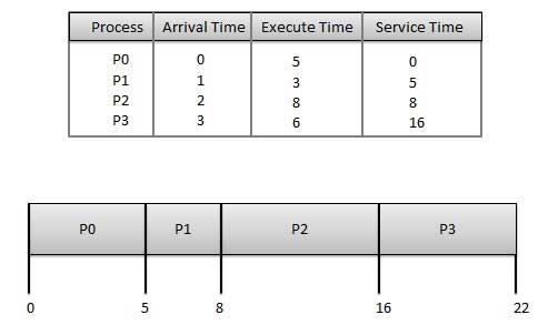
The wait time of each process is as follows −
Process | Wait Time: Service Time - Arrival Time |
P0 | 0 - 0 = 0 |
P1 | 5 - 1 = 4 |
P2 | 8 - 2 = 6 |
P3 | 16 - 3 = 13 |
Average Wait Time: (0+4+6+13) / 4 = 5.75
Shortest Job Next (SJN)
- This is also known as the shortest job first, or SJF
- This is a non-preemptive, pre-emptive scheduling algorithm.
- The best approach to minimize waiting time.
- Easy to implement in Batch systems where required CPU time is known in advance.
- Impossible to implement in interactive systems where required CPU time is not known.
- The processer should know in advance how much time the process will take.
Given: Table of processes, and their Arrival time, Execution time
Process | Arrival Time | Execution Time | Service Time |
P0 | 0 | 5 | 0 |
P1 | 1 | 3 | 5 |
P2 | 2 | 8 | 14 |
P3 | 3 | 6 | 8 |

The waiting time of each process is as follows −
Process | Waiting Time |
P0 | 0 - 0 = 0 |
P1 | 5 - 1 = 4 |
P2 | 14 - 2 = 12 |
P3 | 8 - 3 = 5 |
Average Wait Time: (0 + 4 + 12 + 5)/4 = 21 / 4 = 5.25
Priority Based Scheduling
- Priority scheduling is a non-preemptive algorithm and one of the most common scheduling algorithms in batch systems.
- Each process is assigned a priority. The process with the highest priority is to be executed first and so on.
- Processes with the same priority are executed on a first-come-first-served basis.
- Priority can be decided based on memory requirements, time requirements, or any other resource requirement.
Given: Table of processes, and their Arrival time, Execution time, and priority. Here we are considering 1 is the lowest priority.
Process | Arrival Time | Execution Time | Priority | Service Time |
P0 | 0 | 5 | 1 | 0 |
P1 | 1 | 3 | 2 | 11 |
P2 | 2 | 8 | 1 | 14 |
P3 | 3 | 6 | 3 | 5 |

The waiting time of each process is as follows −
Process | Waiting Time |
P0 | 0 - 0 = 0 |
P1 | 11 - 1 = 10 |
P2 | 14 - 2 = 12 |
P3 | 5 - 3 = 2 |
Average Wait Time: (0 + 10 + 12 + 2)/4 = 24 / 4 = 6
Shortest Remaining Time
- The shortest remaining time (SRT) is the preemptive version of the SJN algorithm.
- The processor is allocated to the job closest to completion but it can be preempted by a newer ready job with a shorter time to completion.
- Impossible to implement in interactive systems where required CPU time is not known.
- It is often used in batch environments where short jobs need to give preference.
Round Robin Scheduling
- Round Robin is the preemptive process scheduling algorithm.
- Each process is provided a fixed time to execute, it is called a quantum.
- Once a process is executed for a given period, it is preempted and another process executes for a given period.
- Context switching is used to save states of preempted processes.
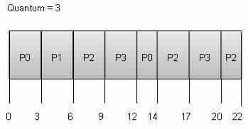
The wait time of each process is as follows −
Process | Wait Time: Service Time - Arrival Time |
P0 | (0 - 0) + (12 - 3) = 9 |
P1 | (3 - 1) = 2 |
P2 | (6 - 2) + (14 - 9) + (20 - 17) = 12 |
P3 | (9 - 3) + (17 - 12) = 11 |
Average Wait Time: (9+2+12+11) / 4 = 8.5
Multiple-Level Queues Scheduling
Multiple-level queues are not an independent scheduling algorithm. They make use of other existing algorithms for the group and schedule jobs with common characteristics.
- Multiple queues are maintained for processes with common characteristics.
- Each queue can have its scheduling algorithms.
- Priorities are assigned to each queue.
For example, CPU-bound jobs can be scheduled in one queue and all I/O-bound jobs in another queue. The Process Scheduler then alternately selects jobs from each queue and assigns them to the CPU based on the algorithm assigned to the queue.
KEY TAKEAWAY
A Process Scheduler schedules different processes to be assigned to the CPU based on particular scheduling algorithms. There are six popular process scheduling algorithms which we are going to discuss in this chapter −
- First-Come, First-Served (FCFS) Scheduling
- Shortest-Job-Next (SJN) Scheduling
- Priority Scheduling
- Shortest Remaining Time
- Round Robin(RR) Scheduling
- Multiple-Level Queues Scheduling
In multiple-processor planning multiple CPUs square measure accessible and therefore Load Sharing becomes doable. But multiple processor planning is additionally advanced as compared to single processor planning. In multiple-processor planning their square measure cases once the processors square measure identical i.e. uniform, in terms of their practicality, we can use any methodor access to run any process within the queue.
Approaches to Multiple-Processor planning –
One approach is once all the planning selections and I/O process square measure handled by one processor that is termed the Master Server and therefore the alternative processors executes solely the user code. This is often straightforward and reduces the requirement of knowledge sharing. This whole state of affairs is termed uneven parallel processing.
A second approach uses biradial parallel processing wherever every processor is self-planning. All processes could also be during a common prepared queue or every processor could have its non-public queue for prepared processes. The planning income additional by having the hardware for every methodor examine the prepared queue and choose a process to execute.
Processor Affinity –
Processor Affinity means that a process has AN affinity for the processor on that it's presently running.
When a method runs on a particular processor there square measure bound effects on the cache memory. The information last accessed by {the method|the method} populate the cache for the methodor and as a result serial operation by the process square measure typically glad within the cache memory. Currently, if the method migrates to a different processor, the contents of the cache memory should be invalid for the primary processor and therefore the cache for the second processor should be repopulated. As a result of the high price of disconfirming and repopulating caches, most of the SMP(symmetric multiprocessing) systems attempt to avoid migration of methods from one processor to a different and check out to stay a process running on an equivalent processor. This is often called PROCESSOR AFFINITY.
There square measure 2 varieties of processor affinity:
1. Soft Affinity – once AN package includes a policy of attempting to stay a method running on an equivalent processor however not guaranteeing it'll do therefore, this example is termed soft affinity.
2. Laborious Affinity – laborious Affinity permits a method to specify a set of processors on that it should run. Some systems like UNIX operating system implements soft affinity however additionally give some system calls like sched_setaffinity() that supports laborious affinity.
Load leveling –
Load leveling is that the phenomenon that keeps the work equally distributed across all processors in the AN SMP system. Load leveling is critical solely on systems wherever every method has its non-public queue of the process that square measure eligible to execute. Load leveling is senseless as a result of once a methodor becomes idle it immediately extracts a runnable process from the common run queue. On SMP(symmetric multiprocessing), it's necessary to stay the work balanced among all processors to completely utilize the advantages of getting quite one processor else one or additional processor can sit idle whereas alternative processors have high workloads besides lists of processors awaiting the C.P.U.
There square measure 2 general approaches to load leveling :
1. Push Migration – In push migration, a task habitually checks the load on every processor ANd if it finds an imbalance then it equally distributes the load on every processor by moving the processes from overladen to idle or less busy pro-cessors.
2. Pull Migration – Pull Migration happens once AN idle processor pulls a waiting task from a busy processor for its execution.
Multicore Processors –
In multi-core processors, multiple processor cores square measure places on an equivalent physical chip. Every core includes a register set to keep up its study state and so seems to the package as a separate physical processor. SMP systems that use multicore processors square measure quicker and consume less power than systems during which every processor has its physical chip.
However, multicore processors could complicate the planning issues. Once the processor accesses memory then it spends a major quantity of your time watching for the information to become accessible. This example is termed MEMORY STALL. It happens for varied reasons like cache miss, which is accessing the information that's not within the cache memory. In such cases, the processor will pay up to one-half of its time watching for knowledge to become accessible from the memory. To unravel this downside recent hardware styles have enforced multithreaded processor cores during which 2 or additional hardware threads square measure assigned to every core. So if one thread stalls whereas watching for the memory, the core will switch to a different thread.
There square measure 2 ways in which to multithread a processor :
1. Coarse-Grained Multithreading – In coarse-grained multithreading, a thread executes on a processor till an extended latency event like a memory stall happens, as a result of the delay caused by the long latency event, the processor should switch to a different thread to start execution. The price of switch between threads is high because the instruction pipeline should be terminated before the opposite thread will begin execution on the processor core. Once this new thread begins execution it begins filling the pipeline with its directions.
2. Fine-Grained Multithreading – This multithreading switches between threads at a far finer level chiefly at the boundary of AN instruction cycle. The study style of fine-grained systems embraces logic for thread switch and as a result, the price of switch between threads is little.
Virtualization and Threading –
In this type of multiple-processor scheduling, even a single CPU system acts like a multiple-processor system. In a system with Virtualization, the virtualization presents one or more virtual CPUs to each of the virtual machines running on the system and then schedules the use of physical CPU among the virtual machines. Most virtualized environments have one host operating system and many guest operating systems. The host operating system creates and manages virtual machines. Each virtual machine has a guest operating system installed and applications run within that guest. Each guest operating system may be assigned for specific use cases, applications, or users including time-sharing or even real-time operation. Any guest operating-system scheduling algorithm that assumes a certain amount of progress in a given amount of time will be negatively impacted by the virtualization. A time-sharing operating system tries to allot 100 milliseconds to each time slice to give users a reasonable response time. A given 100 millisecond time slice may take much more than 100 milliseconds of virtual CPU time. Depending on how busy the system is, the time slice may take a second or more which results in a very poor response time for users logged into that virtual machine. The net effect of such scheduling layering is that individual virtualized operating systems receive only a portion of the available CPU cycles, even though they believe they are receiving all cycles and that they are scheduling all of those cycles. Commonly, the time-of-day clocks in virtual machines are incorrect because timers take no longer to trigger than they would on dedicated CPUs.
Virtualizations can thus undo the good scheduling-algorithm efforts of the operating systems within virtual machines.
KEY TAKEAWAY
In multiple-processor planning multiple CPUs square measure accessible and therefore Load Sharing becomes doable. But multiple processor planning is additionally advanced as compared to single processor planning. In multiple-processor planning their square measure cases once the processors square measure identical i.e. uniform, in terms of their practicality, we can use any methodor accessible to run any process within the queue.
Introduction to Deadlock
Every process needs some resources to complete its execution. However, the resource is granted in sequential order.
- The process requests some resources.
- OS grants the resource if it is available otherwise let the process waits.
- The process uses it and releases on completion.
A Deadlock is a situation where each of the computer processes waits for a resource that is being assigned to some another process. In this situation, none of the processes gets executed since the resource it needs, is held by some other process which is also waiting for some other resource to be released.
Let us assume that there are three processes P1, P2, and P3. There are three different resources R1, R2, and R3. R1 is assigned to P1, R2 is assigned to P2, and R3 is assigned to P3.
After some time, P1 demands R1 which is being used by P2. P1 halts its execution since it can't complete without R2. P2 also demands R3 which is being used by P3. P2 also stops its execution because it can't continue without R3. P3 also demands R1 which is being used by P1 therefore P3 also stops its execution.
In this scenario, a cycle is being formed among the three processes. None of the processes is progressing and they are all waiting. The computer becomes unresponsive since all the processes got blocked.
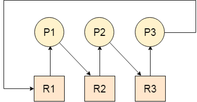
Fig 12 - Deadlock
Difference between Starvation and Deadlock
Sr. | Deadlock | Starvation |
1 | Deadlock is a situation where no process got blocked and no process proceeds | Starvation is a situation where the low priority process got blocked and the high priority processes proceed. |
2 | Deadlock is an infinite waiting. | Starvation is a long waiting but not infinite. |
3 | Every Deadlock is always starvation. | Every starvation need not be deadlock. |
4 | The requested resource is blocked by the other process. | The requested resource is continuously be used by the higher priority processes. |
5 | Deadlock happens when Mutual exclusion, hold and wait, No preemption, and circular wait occur simultaneously. | It occurs due to the uncontrolled priority and resource management. |
Necessary conditions for Deadlocks
- Mutual Exclusion
A resource can only be shared in a mutually exclusive manner. It implies if two processes cannot use the same resource at the same time.
2. Hold and Wait
A process waits for some resources while holding another resource at the same time.
3. No preemption
The process which once scheduled will be executed till the completion. No other process can be scheduled by the scheduler meanwhile.
4. Circular Wait
All the processes must be cyclically waiting for the resources so that the last process is waiting for the resource which is being held by the first process.
System model
In a multiprogramming system, numerous processes get competed for a finite number of resources. Any process requests resources, and as the resources aren't available at that time, the process goes into a waiting state. At times, a waiting process is not at all able again to change its state as other waiting processes detain the resources it has requested. That condition is termed as deadlock. In this chapter, you will learn about this issue briefly in connection with semaphores.
A system model or structure consists of a fixed number of resources to be circulated among some opposing processes. The resources are then partitioned into numerous types, each consisting of some specific quantity of identical instances. Memory space, CPU cycles, directories and files, I/O devices like keyboards, printers, and CD-DVD drives are prime examples of resource types. When a system has 2 CPUs, then the resource type CPU got two instances.
Under the standard mode of operation, any process may use a resource in only the below-mentioned sequence:
- Request: When the request can't be approved immediately (where the case may be when another process is utilizing the resource), then the requesting job must remain waited until it can obtain the resource.
- Use: The process can run on the resource (like when the resource is a printer, its job/process is to print on the printer).
- Release: The process releases the resource (like, terminating or exiting any specific process).
A deadlock state can occur when the following four circumstances hold simultaneously within a system:
- Mutual exclusion: At least there should be one resource that has to be held in a non-sharable manner; i.e., only a single process at a time can utilize the resource. If another process demands that resource, the requesting process must be postponed until the resource gets released.
- Hold and wait: A job must be held at least one single resource and waiting to obtain supplementary resources which are currently being held by several other processes.
- No preemption: Resources can't be anticipated; i.e., a resource can get released only willingly by the process holding it, then after that, the process has completed its task.
- Circular wait: The circular - wait for situation implies the hold-and-wait state or condition, and hence all the four conditions are not completely independent. They are interconnected among each other.
Normally you can deal with the deadlock issues and situations in one of the three ways mentioned below:
- You can employ a protocol for preventing or avoiding deadlocks, and ensure that the system will never go into a deadlock state.
- You can let the system to enter any deadlock condition, detect it, and then recover.
- You can overlook the issue altogether and assume that deadlocks never occur within the system.
But is recommended to deal with deadlock, from the 1st option
Deadlock characterization
In a deadlock, processes never complete their execution, and system resources are tied up, keeping different jobs from the beginning.
Necessary Conditions
A deadlock occurs in the operating system when at least two processes need some resource to finish their execution that is held by the different process.
A deadlock happens if the four Coffman conditions prove to be true. But, these conditions are not related. They are described as follows:
Mutual Exclusion
There ought to be a resource that must be held by one process at once.
In the figure below, there is a single instance of Resource 1 and it is held by Process 1 as it were.


Allocated

Fig 13 – Single instance
Hold and Wait
A process can hold numerous resources and still demand more resources from different processes that are holding them.
In the graph given beneath, Process 2 holds Resource 2 and Resource 3 and is mentioning Resource 1 which is held by Process 1.

Fig 14 – Hold and wait
No Preemption
A resource can't be pre-empted forcefully from a process. A process can just release a resource wishfully.
In the graph underneath, Process 2 can't preempt Resource 1 from Process 1. It might be discharged when Process 1 gives up it intentionally after its execution is finished.

Fig 15 – No pre-emption
Circular Wait
A process is waiting for the resource held continuously by another process, which is waiting for the resource held by the third process, etc, till the last process is waiting for a resource held by the first process. These structures around the chain.
For instance: Process 1 is assigned Resource 2 and it is requesting Resource 1. Likewise, Process 2 is assigned Resource 1 and it is requesting Resource 2. This structures a circular wait loop.
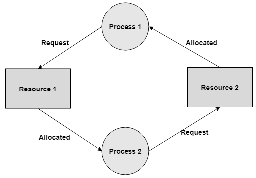
Fig 16 – Circular wait
Resource-Allocation Graph
A resource allocation graph shows which resource is held by which process and which process is waiting for a resource of a specific kind.
It is an amazing and straightforward tool to outline how interacting processes can deadlock.
Therefore, the resource allocation graph describes what is the condition of the system as far as processes and resources are concerned. Like what several resources are accessible, what number of are allotted, and what is the request of each process.
Everything can be represented in terms of a graph.
One of the benefits of having a graph is, sometimes it is conceivable to see a deadlock straightforwardly by utilizing RAG, and however you probably won’t realize that by taking a glance at the table.
Yet, the tables are better if the system contains bunches of process and resource and the Graph is better if the system contains less number of process and resource.
We realize that any diagram contains vertices and edges. So RAG likewise contains vertices and edges. In RAG vertices are of two sort –
Process vertex – Every process will be shown as a process vertex. In RAG, the process will be drawn with a circle.
Resource vertex – Every resource will be shown as a resource vertex. It is likewise of two types –
Single instance type resource – It is drawn as a rectangle, inside the rectangle, there will be one dot. So the quantity of dots demonstrates what number of instances are available of every resource type.
Multi-resource instance type resource – It is also shown as a rectangle, inside the rectangle, there will be numerous dots present.
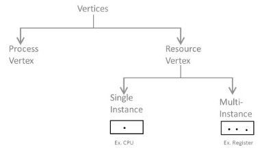
Fig 17
There are two kinds of edges in RAG –
Assign Edges-
Assign edges shows the assigned resources to the processes.
They are drawn as an arrow pointed towards the process and the tail focuses on the resource.
Request Edges-
Request edges show the waiting condition of processes for the resources.
They are drawn as an arrow where the head of the arrow indicates the instance of the resource and the tail of the arrow focuses on the process.
On the off chance that a process requires 'n' instances of a resource type, at that point 'n' assign edges will be drawn.
Example- Resource Allocation Graph is shown in the figure below:
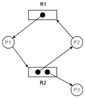
Fig 18 - Resource Allocation Graph
The above graph describes the accompanying data:
There exist three processes in the system P1, P2, and P3 respectively.
There exist two resources in the system to be specific R1 and R2.
Resource R1 has a single instance and resource R2 has two instances.
Process P1 holds one instance of resource R1 and is waiting for an instance of resource R2.
Process P2 holds one instance of resource R2 and is waiting for an instance of resource R1.
Process P3 holds one instance of resource R2 and isn't waiting for anything.
Prevention
Deadlock prevention algorithms guarantee that in any event one of the essential conditions (Mutual exclusion, hold and wait, no preemption, and circular wait) does not remain constant.
This methodology includes structuring a system that violates one of the four fundamental conditions required for the event of a deadlock.
This guarantees the system stays free from the deadlock.
Anyway, most deadlock prevention algorithms have poor resource usage, and consequently, bring about diminished throughputs.
Mutual Exclusion
The mutual exclusion condition must hold for non-sharable resources. For instance, a printer can't be at the same time shared by a few processes.
Sharable resources, conversely, don't require mutually exclusive access and in this manner can't be associated with a deadlock.
Read-only files are a genuine case of a sharable resource. If many processes endeavor to open a read-only file at the same time, they can be able to access the file simultaneously.
A process will never wait for a sharable resource. As a rule, be that as it may, we can't prevent deadlock by denying the mutual exclusion condition, since certain resources are inherently non-sharable.
Hold and Wait
To avoid this condition processes must be kept from holding at least one resource while at the same time waiting for at least one other. There are a few conceivable outcomes for this:
Necessitate that all processes demand all resources one at the same time. This can be a wastage of system resources if a process needs one resource in the initial stage of its execution and does not need some other resource until some other time.
Necessitate that processes holding resources must discharge them before requesting new resources, and after that re-acquire the resources alongside the new ones out of a single new demand. This can be an issue if a process has somewhat finished an activity utilizing a resource and, at that point neglects to get it re-allocated after releasing it.
Both of the strategies portrayed above can prompt starvation if a process requires at least one well-known resources.
No Preemption
Preemption of process resource allocations can anticipate this state of deadlocks when it is conceivable.
One methodology is that if a process is compelled to hold up when mentioning another resource, at that point every other resource recently held by this process are certainly discharged, (appropriated), constraining this process to re-acquire the old resources alongside the new resources in a single request.
Another methodology is that when a resource is requested and not accessible, at that point the system hopes to perceive what different processes right now have those resources and are themselves blocked waiting for some other resource. On the off chance that such a process is discovered, at that point, a portion of their resources may get acquired and added to the list of resources for which the process is waiting.
Both of these methodologies might be relevant for resources whose states are effectively saved and resorted, for example, registers and memory, yet are commonly not applicable to different devices, for example, printers and tape drives.
Circular Wait
One approach to stay away from circular wait is to number all resources, and to require that processes request resources just in carefully expanding (or diminishing) order.
In contrast, to demand resource Rj, a process should initially discharge all Ri with the end goal that i >= j.
One major test in this plan is deciding the overall request of the various resources.
Approach
A natural number is allotted to each resource.
Each process is permitted to demand the resources either in just ascending or descending order of the resource number.
If ascending request is followed, if a process requires a lesser number of resources, at that point it must release every one of the resources having a bigger number and the other way around.
This methodology is the most functional methodology and implementable.
Nonetheless, this methodology may cause starvation however will never prompt deadlock.
Avoidance and detection
Deadlock Avoidance
The deadlock-prevention algorithm prevents the occurrence of deadlock by limiting how demands can be made. The restrictions guarantee that at any rate one of the vital conditions for deadlock can't happen and, thus, deadlock can't occur.
Conceivable drawbacks of preventing deadlocks by this strategy, in any case, result in low device usage and decreased system throughput.
An alternative strategy for staying away from deadlocks is to require extra data about how resources are requested.
In this respect, each request requires that the system keeps a record of the resources as of now available, the resources at present assigned to each process, and the future demands and releases of each process.
The different algorithms that utilize this methodology vary in the sum and type of data required. The least complex and most valuable model necessitates that each process proclaims the most maximum number of resources of each instance that it might require.
Given this as earlier data, it is conceivable to develop an algorithm that guarantees that the system will never enter a deadlock state. Such a calculation characterizes the deadlock avoidance approach.
A deadlock avoidance approach powerfully looks at the resource-assignment state to guarantee that a circular wait condition can never exist.
The resource-allocation state is characterized by the number of available and allotted resources and the most extreme requests of the processes.
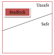
Safe State
A state is safe if the system can assign resources to each process (up to its most extreme) in some sequence and still will be able to maintain a deadlock-free state.
In other words, a system is in a safe state if there exists a safe sequence.
An arrangement of processes <P1, P2, ..., Pn> is a safe arrangement for the present allocation state if, for each Pi, the resource requests that Pi make can be fulfilled by the currently accessible resources in addition to the resources held by all Pj, with j < i.
In this circumstance, the resources that Pi needs are not quickly available, at that point then Pi can wait until all Pj have completed.
When all Pj have completed, Pi can acquire the majority of its required resources, complete its assigned task, and return its allotted resources, and will terminate.
At the point when Pi ends, Pi+l can get its required resources, and so on.
If no such sequence exists, at that point, the system state is said to be unsafe.
A safe state is not a deadlock state. On the other hand, a deadlock state is an unsafe state. All the unsafe state are not deadlocked.
Consider a system with 10 magnetic tape drives and 3 processes P0, P1, and P2 respectively. The maximum requirement and current needs of each process are shown in the table below.
Process | Maximum needs | Current allocated |
P0 | 8 | 4 |
P1 | 4 | 2 |
P2 | 8 | 2 |
Process P0 is having 4 tape drives, P1 is having 2 tape drives and P2 is having 2 tape drives.
For a safe sequence process, P0 needs 4 more tape drives to completes its execution. Similarly, process P1 needs 2 and P2 needs 6. Total available resources are 2.
Since process P0 needs 5 tape drives, but availability is only 2, so process P1 will wait till gets resources. Process P1 needs only 2 so its request will be fulfilled and as P1 will finish its execution it will return all resources.
Now currently available resources are 4. Then process P2 will wait as available resources are 4 and P2 needs 6.
The system will now fulfill the needs of P0. Process P0 will execute and release its all resources. Now available resources are 8. And in the last request of the process P2 will be fulfilled.
So, the safe sequence will be <P1, P0, P2>.
There is one thing to be noted here that any system can go from a safe state to an unsafe state if any process requests more resources.
Resource-Allocation-Graph Algorithm
Deadlock can be detected in a system through cycles only if the resources have just single instances in the resource-allocation graphs.
For this situation, unsafe states can be identified and avoided by adding a claim edge in the resource-allocation graph, represented by dashed lines, which point from a process to a resource that it might request later on.
All claim edges must be added to the graph for a specific process before that process is allowed to demand any resources.
At the point when a process makes a request, the claim edge Pi->Rj is changed over to a request edge. Essentially when a resource is released, the task returns to a claim edge.
This methodology works by denying demands that would deliver cycles in the resource-allocation graph, producing claim edges into results.
Consider for instance what happens when process P2 request resource R2:
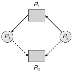
Fig 19
The subsequent resource-allocation graph would have a cycle in it, thus the request can't be granted.
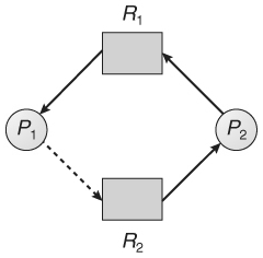
Fig 20
Banker’s Algorithm
Resource allocation graph works only for a single instance. In the case of more than one instance, an alternative approach is used known as the banker's algorithm.
The Banker's Algorithm gets its name since it is a strategy that bankers could use to guarantee that when they loan out resources they will even now have the option to fulfill every one of their client's requests.
At the point when a process starts, it must state ahead of time the maximum resources it might ask for, up to the amount available on the system.
At the point when a request is made, the scheduler decides if giving the request would leave the system in a safe state. In case, the process did not get a chance it must wait until the request can be granted securely.
The banker’s algorithm depends on a few key data structures: (where n is the number of processes and m is the number of resource types.)
Available[m] demonstrates what numbers of resources are at present available of each kind.
Max[n][m] demonstrates the maximum request of each process of every resource.
Allocation[n][m] demonstrates the quantity of every resource class allocated to each process.
Need[n][m] demonstrates the rest of the resources required of each type for each process. (Note that Need[i][j] = Max[i][j] - Allocation[i][j] for all i, j)
For simplification of the concept, we mention the accompanying notations/objective facts:
One row of the Need vector, Need[i], can be treated as a vector comparing to the requirements of process i, and comparatively for Allocation and Max.
A vector X is viewed as <= a vector Y if X[i] <= Y[i] for all i.
Safety Algorithm
We would now be able to exhibit the algorithm for seeing if or not a system is in a safe state. This algorithm can be portrayed as follows:
Assume Work and Finish to be vectors of length m and n, individually. Initialize
Work = Available and Finish[i] = false for i = 0, 1, ... , n - 1.
Find an index i with the end goal that both
Finish[i] = = false
Needi ≤ Work
On the off chance that no such i exists, go to step 4.
Work = Work + Allocation;
Finish[i] = true
Go to step 2.
In case Finish[i] = = true for all i, at that point the system is in a safe state.
This algorithm may require a request for m x n2 operations to decide if a state is safe or not.
Resource-Request Algorithm
Next, we depict the algorithm for deciding if requests can be securely allowed or not.
Assume Requesti be the request vector for process Pi. If Requesti [j] = = k, at that point process Pi needs k instances of resource type Rj. At the point when a request for resources is made by process Pi, the accompanying actions are made:
If Requesti ≤ Needi, go to step 2. Otherwise, raise an error condition, since the process has exceeded its maximum claim.
If Requesti ≤ Available, go to step 3. Otherwise Pi must wait since the resources are not accessible.
Have the system claim to have assigned the requested resources to process Pi by modifying the state as follows:
Available = Available – Requesti ;
Allocationi = Allocationi + Requesti ;
Needi = Needi – Requesti ;
In case the final resource-allocation state is safe, the transaction is finished, and process Pi is allocated its resources. Nonetheless, if the new state is unsafe, at that point Pi must wait for Requesti, and the old resource-allocation state is restored.
Example
Considering a system with five processes P0 through P4 and three resources of type A, B, C. Resource type A has 10 instances, B has 5 instances and type C has 7 instances. Suppose at time t0 following snapshot of the system has been taken:
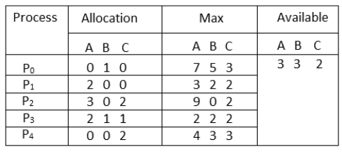
Question1. What will be the content of the Need matrix?
Need [i, j] = Max [i, j] – Allocation [i, j]
So, the content of Need Matrix is:
Process | Need | ||
A | B | C | |
P0 | 7 | 4 | 3 |
P1 | 1 | 2 | 2 |
P2 | 6 | 0 | 0 |
P3 | 0 | 1 | 1 |
P4 | 4 | 3 | 1 |
Question2. Is the system in a safe state? If yes, then what is the safe sequence?
Applying the Safety algorithm on the given system,
For P0, Need [7 4 3] < Available [3 3 2]
Finish = False, P0 will wait.
For P1, Need [1 2 2] < Available [3 3 2]
Finish = True
Available = Available + Allocation = [3 3 2] + [2 0 0] = [5 3 2]
For P2, Need [6 0 0] = Available [5 3 2]
Finish = False, P2 will wait.
For P3, Need [0 1 1] = Available [5 3 2]
Finish = True
Available = Available + Allocation = [5 3 2] + [2 1 1] = [7 4 3]
For P4, Need [4 3 1] = Available [7 4 3]
Finish = True
Available = Available + Allocation = [7 4 3] + [0 0 2] = [7 4 5]
For P0, Need [7 4 3] = Available [7 4 5]
Finish = True
Available = Available + Allocation = [7 4 5] + [0 1 0] = [7 5 5]
For P2, Need [6 0 0] = Available [7 5 5]
Finish = True
Available = Available + Allocation = [7 5 5] + [3 0 2] = [10 5 7]
Therefore, the safe sequence is <P1, P3, P4, P0, P2>
Deadlock Detection
Deadlock detection is the process of really verifying that a deadlock exists and distinguishing the processes and resources engaged in the deadlock.
The essential thought is to check allocation against resource availability for all conceivable allocation sequences to decide whether the system is in a deadlocked state.
The deadlock detection algorithm is just 50% of this procedure. When a deadlock is recognized, there should be an approach to recover a few choices exists:
A single instance of resource: Here to detect deadlock, we can run an algorithm to check for the cycle in the Resource Allocation Graph. The presence of a cycle in the graph is an adequate condition for deadlock.
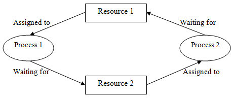
In the above graph, resource 1 and resource 2 have single occasions. There is a cycle R1 → P1 → R2 → P2. Thus, Deadlock is confirmed.
Multiple instances of resources: Detection of the cycle is an essential yet not adequate condition for deadlock detection, for this situation, the system might be in halt fluctuates as per various circumstances.
Recovery from deadlock
At the point when a Deadlock Detection Algorithm verifies that a deadlock has happened in the system, the system must recover from that deadlock. There are two methodologies of breaking a Deadlock:
- Process Termination: To wipe out the deadlock, we can just kill at least one process. For this, we utilize two techniques:
- Abort all the Deadlocked Processes: Aborting every one of the processes will break the deadlock, however with incredible costs. The deadlocked processes may have computed for quite a while and the consequence of those incomplete calculations must be disposed of and there is a likelihood to recalculate them later.
- Abort one process in turn until the deadlock is removed: Abort one deadlocked process in turn, until the deadlock cycle is removed from the system. Because of this technique, there might be reasonable overhead, because after aborting the process, we need to run a deadlock detection algorithm to check whether any processes are yet deadlocked.
- Resource Preemption: To remove deadlock we can utilize resource pre-emption. We preempt a few resources from processes and give those resources to different processes. This strategy will raise three issues –
- Choosing a victim: We should figure out which resources and which processes are to be preempted and the request to limit the expense.
- Rollback: We should figure out what action will be taken for the process from which resources are preempted. One solution is all rollback. That implies aborting the process and restarts it.
- Starvation: In a system, the equivalent process might be constantly picked as a victim. Subsequently, that process will never finish its assigned task. This circumstance is called Starvation and must be kept away from. One arrangement is that a process must be picked as a victim just a limited number of times.
KEY TAKEAWAY
Every process needs some resources to complete its execution. However, the resource is granted in sequential order.
- The process requests some resources.
- OS grants the resource if it is available otherwise let the process waits.
- The process uses it and releases on completion.
A Deadlock is a situation where each of the computer processes waits for a resource that is being assigned to some other process. In this situation, none of the processes gets executed since the resource it needs, is held by some other process which is also waiting for some other resource to be released.
References:
1. Silberschatz, Galvin and Gagne, “Operating Systems Concepts”, Wiley
2. Sibsankar Halder and Alex A Aravind, “Operating Systems”, Pearson Education
3. Harvey M Dietel, “ An Introduction to Operating System”, Pearson Education
4. D M Dhamdhere, “Operating Systems: A Concept-based Approach”, 2nd Edition,
5. TMH 5. William Stallings, “Operating Systems: Internals and Design Principles ”, 6th Edition, Pearson Education