Unit 1
Sensors and Transducers
Sensors are devices that perform input function in a system which ‘sense’ the changes in a quantity. The best example of a sensor is a mercury thermometer. Here the quantity measured is heat or temperature. The measured temperature is converted to a readable value on the calibrated glass tube, based on the expansion and contraction of liquid mercury.
Transducers are used to convert the energy of one kind into the energy of another kind, for example, a microphone is the input device that converts sound waves into electrical signals for the amplifier to amplify a process, and a loudspeaker is the output device that converts these electrical signals back into sound waves.
An example of this type of simple Input/Output (I/O) system is given below.

Figure1. Working principle of the transducer.
Key Take-Aways:
The main difference between sensor and transducer is, the sensor is a physical device, that senses a physical quantity and then converts it into signals which can be read by an instrument or the user. The transducer is also a physical device, that converts one form of energy into another form.
Classification:
Based on the quantity being measured
Active and passive sensors:
Based on power requirement sensors are classified as active and passive.
Active sensors are those which do not require an external power source for their functioning. They generate power within themselves to operate and hence called a self-generating type. The energy for functioning is derived from the quantity being measured.
For example, piezoelectric crystal generates electrical output (charge) when subjected to acceleration.
Passive sensors require an external power source for their functioning. Most of the resistive, inductive, and capacitive sensors are passive.
Analog and digital sensor:
An analog sensor converts the physical quantity being measured to analog form (continuous in time). Thermocouple, RTD, strain gauge are called analog sensors. A digital sensor produces output in the form of a pulse.
Encoders are an example of digital sensors.
Inverse sensors:
Some sensors can sense the physical quantity to convert it to other forms and also sense the output signal form to get back the quantity in the original form.
For example, a piezoelectric crystal when subjected to vibration generates a voltage. At the same time when a piezo crystal is subjected to varying voltage, they begin to vibrate. This property makes them suitable to use in microphones and speakers.
Certain features have to be considered when choosing a sensor:
Accuracy – Should be high
Stability – Maintain under abnormal condition
Environmental condition – Usually has limits for temperature and humidity
Range – Measurement limit of sensor
Calibration -Essential for most of the measuring devices as the readings changes with time.
Resolution – Smallest increment detected by the sensor.
Cost – Should be low.
Power Consumption – Low
Repeatability – The reading that varies is repeatedly measured under the same environment.
The circuit diagram of the resistive transducer, which is used to measure displacement is shown below figure.
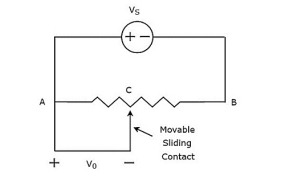
Figure 2. Measurement of displacement using a potentiometer
The circuit consists of a potentiometer and a voltage source, VS. We can say that these two are connected in parallel with respect to points A & B. The
The potentiometer has a sliding contact, which can be varied. So, point C is a variable one. In the above circuit, the output voltage, Vo is measured across points A & C.
Mathematically, the relation between the voltages and distances can be represented as
Vo/Vs = AC/AB
Therefore, we connect the body whose displacement is to be measured to the sliding contact. So, whenever the body moves in a straight line, point C also varies. Due to this, the output voltage, Vo also changes accordingly.
In this case, we can find the displacement by measuring the output voltage.
Key Take-Aways:
The potentiometer is also called pots and it one of the most commonly used devices for measuring the displacement of the body.
LVDT comprises a cylindrical former, which is bounded by one main winding in the hub of the former and the two minor LVDT windings wound on the surfaces. The amount of twists in both the minor windings is equivalent, but they are reversed to each other like clockwise direction and anti-clockwise direction.
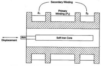
Figure 3. Linear Variable Differential Transformer
For this reason, the o/p voltages will be the variation in voltages among the two minor coils. These two coils are denoted with S1 & S2. Esteem iron core is located in the middle of the cylindrical former. The excitation voltage of AC is 5-12V and the operating frequency is given by 50 to 400 HZ.
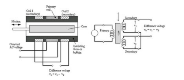
Figure4. LVDT working principle
The working of the LVDT circuit diagram is divided into three cases based on the position of the iron core in the insulated former.
The output of LVDT is a sine wave through amplitude that is proportional to off-center location & 0⁰ otherwise 180⁰ of phase based on the located side of the core. Here, full-wave rectification is used to demodulate the signal.
Optical Encoder
An optical encoder is an electromechanical device that has an electrical output in digital form proportional to the angular position of the input shaft.
Optical encoders enable an angular displacement to be converted directly into a digital form.
An optical encoder is an angular position sensor :
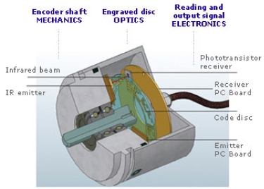
Figure 5. Optical Encoder
It has a shaft mechanically coupled to an input driver which rotates a disc rigidly fixed to it. A succession of opaque and clear segments is marked on the surface of the disc.
Light from infrared emitting diodes reaches the infrared receivers through the transparent slits of the rotating disc. An analogue signal is created.
Then electronically, the signal is amplified and converted into digital form. This signal is then transmitted to the data processor.
Key Take-Aways:
A linear variable differential transformer (LVDT), a type of inductive absolute encoder, to determine the linear direction of travel and position of the actuator
Force transducers based on strain gauges have a spring element or loaded member where the forces which have to be measured are applied.
The spring element deforms, and strain is produced on the surface.
The task of the spring element is therefore to convert the forces to be measured into strain as reproducibly and linearly as possible. Most of the force transducer properties are defined by the selection of the spring element material and design.
The actual sensor element is the strain gauge (SG), which consists of an insulation layer, the so-called holder, with a measuring grid attached to it. Such strain gauges are bonded to the spring element at suitable points. In general, four strain gauges are used, installed so that two are stretched and two are compressed when force is applied.
These four SG are connected in a Wheatstone bridge circuit. As shown in the drawing below, the Wheatstone bridge is supplied with an excitation voltage. An output voltage then always occurs when the four resistances are different: for example when the resistance of the SG changes due to a strain.
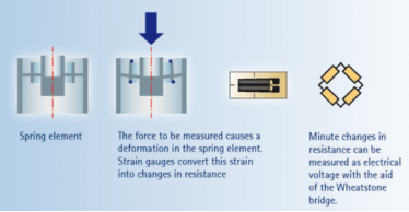
Figure 6. Strain gauge transducer
Key Take-Aways:
A strain gauge is basically used to measure the strain in a workpiece.
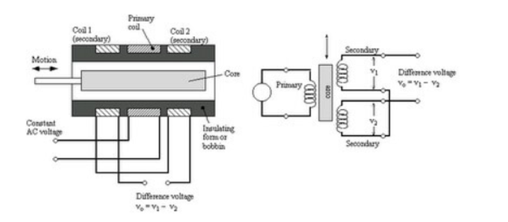
Figure 7. Measurement of pressure using LVDT
Measurement of pressure using the piezoelectric sensor.
Piezoelectricity is the charge created across certain materials when mechanical stress is applied.
Piezoelectric pressure sensors exploit this effect by measuring the voltage across a piezoelectric element generated by the applied pressure.
They are very robust and are used in a wide range of industrial applications.
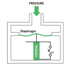
Figure 8. Measurement of pressure using a piezoelectric sensor
When force is applied to a piezoelectric material, an electric charge is generated across the faces of the crystal. This is measured as a voltage proportional to the pressure.
There is also an inverse piezoelectric effect whereupon applying a voltage to the material it will cause to change the shape.
When a static force is given it results in a corresponding charge across the sensor. However, this will leak away over time because of imperfect insulation, the internal sensor resistance, the attached electronics, and so on.
Therefore, piezoelectric sensors are not normally suitable for measuring static pressure. The output signal will gradually drop to zero, even in the presence of constant pressure.
They are, however, sensitive to dynamic changes in pressure across a wide range of frequencies and pressures.
This dynamic sensitivity means they are good at measuring small changes in pressure, even in a very high-pressure environment.
Key Take-Aways:
A pressure measuring instrument generally measures the difference between the unknown pressure (P) and the atmospheric pressure (Pata).
References:
Unit 1
Sensors and Transducers
Sensors are devices that perform input function in a system which ‘sense’ the changes in a quantity. The best example of a sensor is a mercury thermometer. Here the quantity measured is heat or temperature. The measured temperature is converted to a readable value on the calibrated glass tube, based on the expansion and contraction of liquid mercury.
Transducers are used to convert the energy of one kind into the energy of another kind, for example, a microphone is the input device that converts sound waves into electrical signals for the amplifier to amplify a process, and a loudspeaker is the output device that converts these electrical signals back into sound waves.
An example of this type of simple Input/Output (I/O) system is given below.

Figure1. Working principle of the transducer.
Key Take-Aways:
The main difference between sensor and transducer is, the sensor is a physical device, that senses a physical quantity and then converts it into signals which can be read by an instrument or the user. The transducer is also a physical device, that converts one form of energy into another form.
Classification:
Based on the quantity being measured
Active and passive sensors:
Based on power requirement sensors are classified as active and passive.
Active sensors are those which do not require an external power source for their functioning. They generate power within themselves to operate and hence called a self-generating type. The energy for functioning is derived from the quantity being measured.
For example, piezoelectric crystal generates electrical output (charge) when subjected to acceleration.
Passive sensors require an external power source for their functioning. Most of the resistive, inductive, and capacitive sensors are passive.
Analog and digital sensor:
An analog sensor converts the physical quantity being measured to analog form (continuous in time). Thermocouple, RTD, strain gauge are called analog sensors. A digital sensor produces output in the form of a pulse.
Encoders are an example of digital sensors.
Inverse sensors:
Some sensors can sense the physical quantity to convert it to other forms and also sense the output signal form to get back the quantity in the original form.
For example, a piezoelectric crystal when subjected to vibration generates a voltage. At the same time when a piezo crystal is subjected to varying voltage, they begin to vibrate. This property makes them suitable to use in microphones and speakers.
Certain features have to be considered when choosing a sensor:
Accuracy – Should be high
Stability – Maintain under abnormal condition
Environmental condition – Usually has limits for temperature and humidity
Range – Measurement limit of sensor
Calibration -Essential for most of the measuring devices as the readings changes with time.
Resolution – Smallest increment detected by the sensor.
Cost – Should be low.
Power Consumption – Low
Repeatability – The reading that varies is repeatedly measured under the same environment.
The circuit diagram of the resistive transducer, which is used to measure displacement is shown below figure.
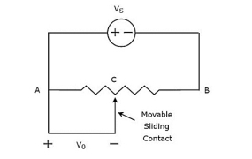
Figure 2. Measurement of displacement using a potentiometer
The circuit consists of a potentiometer and a voltage source, VS. We can say that these two are connected in parallel with respect to points A & B. The
The potentiometer has a sliding contact, which can be varied. So, point C is a variable one. In the above circuit, the output voltage, Vo is measured across points A & C.
Mathematically, the relation between the voltages and distances can be represented as
Vo/Vs = AC/AB
Therefore, we connect the body whose displacement is to be measured to the sliding contact. So, whenever the body moves in a straight line, point C also varies. Due to this, the output voltage, Vo also changes accordingly.
In this case, we can find the displacement by measuring the output voltage.
Key Take-Aways:
The potentiometer is also called pots and it one of the most commonly used devices for measuring the displacement of the body.
LVDT comprises a cylindrical former, which is bounded by one main winding in the hub of the former and the two minor LVDT windings wound on the surfaces. The amount of twists in both the minor windings is equivalent, but they are reversed to each other like clockwise direction and anti-clockwise direction.
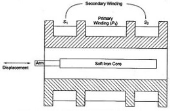
Figure 3. Linear Variable Differential Transformer
For this reason, the o/p voltages will be the variation in voltages among the two minor coils. These two coils are denoted with S1 & S2. Esteem iron core is located in the middle of the cylindrical former. The excitation voltage of AC is 5-12V and the operating frequency is given by 50 to 400 HZ.
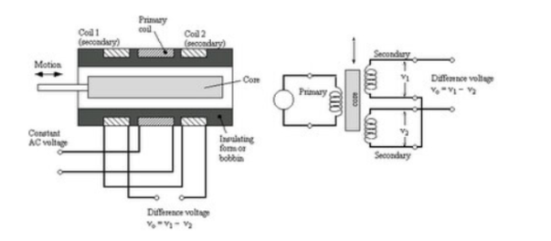
Figure4. LVDT working principle
The working of the LVDT circuit diagram is divided into three cases based on the position of the iron core in the insulated former.
The output of LVDT is a sine wave through amplitude that is proportional to off-center location & 0⁰ otherwise 180⁰ of phase based on the located side of the core. Here, full-wave rectification is used to demodulate the signal.
Optical Encoder
An optical encoder is an electromechanical device that has an electrical output in digital form proportional to the angular position of the input shaft.
Optical encoders enable an angular displacement to be converted directly into a digital form.
An optical encoder is an angular position sensor :
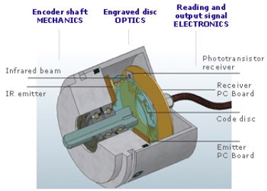
Figure 5. Optical Encoder
It has a shaft mechanically coupled to an input driver which rotates a disc rigidly fixed to it. A succession of opaque and clear segments is marked on the surface of the disc.
Light from infrared emitting diodes reaches the infrared receivers through the transparent slits of the rotating disc. An analogue signal is created.
Then electronically, the signal is amplified and converted into digital form. This signal is then transmitted to the data processor.
Key Take-Aways:
A linear variable differential transformer (LVDT), a type of inductive absolute encoder, to determine the linear direction of travel and position of the actuator
Force transducers based on strain gauges have a spring element or loaded member where the forces which have to be measured are applied.
The spring element deforms, and strain is produced on the surface.
The task of the spring element is therefore to convert the forces to be measured into strain as reproducibly and linearly as possible. Most of the force transducer properties are defined by the selection of the spring element material and design.
The actual sensor element is the strain gauge (SG), which consists of an insulation layer, the so-called holder, with a measuring grid attached to it. Such strain gauges are bonded to the spring element at suitable points. In general, four strain gauges are used, installed so that two are stretched and two are compressed when force is applied.
These four SG are connected in a Wheatstone bridge circuit. As shown in the drawing below, the Wheatstone bridge is supplied with an excitation voltage. An output voltage then always occurs when the four resistances are different: for example when the resistance of the SG changes due to a strain.
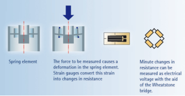
Figure 6. Strain gauge transducer
Key Take-Aways:
A strain gauge is basically used to measure the strain in a workpiece.
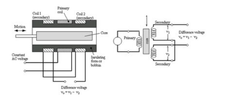
Figure 7. Measurement of pressure using LVDT
Measurement of pressure using the piezoelectric sensor.
Piezoelectricity is the charge created across certain materials when mechanical stress is applied.
Piezoelectric pressure sensors exploit this effect by measuring the voltage across a piezoelectric element generated by the applied pressure.
They are very robust and are used in a wide range of industrial applications.
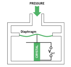
Figure 8. Measurement of pressure using a piezoelectric sensor
When force is applied to a piezoelectric material, an electric charge is generated across the faces of the crystal. This is measured as a voltage proportional to the pressure.
There is also an inverse piezoelectric effect whereupon applying a voltage to the material it will cause to change the shape.
When a static force is given it results in a corresponding charge across the sensor. However, this will leak away over time because of imperfect insulation, the internal sensor resistance, the attached electronics, and so on.
Therefore, piezoelectric sensors are not normally suitable for measuring static pressure. The output signal will gradually drop to zero, even in the presence of constant pressure.
They are, however, sensitive to dynamic changes in pressure across a wide range of frequencies and pressures.
This dynamic sensitivity means they are good at measuring small changes in pressure, even in a very high-pressure environment.
Key Take-Aways:
A pressure measuring instrument generally measures the difference between the unknown pressure (P) and the atmospheric pressure (Pata).
References: