Unit - 2
Transformations, Windowing and Clipping
The transformation means translating some graphics into something else.
It has some rules to apply to the changing graphics.
Some transformations are such as translation, scaling up or down, shearing, rotating, etc.
The transformation that applies on the 2D plane is called as 2D transformation.
It is an important thing in computer graphics to reposition the graphic on the screen and changing its size or orientation.
The homogeneous coordinates are used to perform any transformation such as the translation followed by rotation and the scaling.
The translation follows the sequential process as-
Translate the coordinates
Rotate the translated coordinates
Scale the rotated coordinates to complete the transformation
The process can be shortened by using the matrix of 3*3 instead of using matrix 2*2. This matrix is called a transformation matrix.
To convert 2*2 matrix in 3*3 we have to add just coordinate w.
In this way, the representation of points by 3 numbers instead of 2 numbers, is known as the homogeneous coordinates.
We can represent all the transformation by using homogeneous coordinates in matrix multiplication.
Any Cartesian point can be converted to homogeneous coordinates by P’ (Xh, Yh, h)
Some transformations as scaling, translating, rotating are required to move the image on the screen.
The composite transformation is a transformation that performs two or more transformations one after the other.
The mathematical process is required to move the image in graphics transformation as corresponds to matrix multiplication of transformation matrices and data matrix of homogeneous coordinates.
Reflection Transformation
All the points are reflected or flipped on a line called axis reflection or line of reflection.
The reflection can be referred to as an axis of symmetry or mirror line.
The reflected diagram is the same as the original diagram is known as isometric transformation.
The reflected diagram is facing in opposite direction.
Following figure 2.4 shows the reflection transformation.
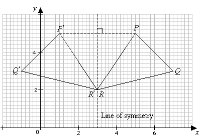
Fig. 1
Shearing Transformation
The shear transformation is used for slanting the shape of the object.
Shearing is also known as skewing.
There are two shear transformations X-shear and Y-shear.
The X-shear shifts the X coordinates and the Y-shear shifts the Y coordinates.
In both cases only one coordinate changes and the other preserves.
X-shear:
It preserves the Y coordinate and changes made with the X coordinate.
Hence only vertical lines of the object get tilt on the right or left side as shown in the below figure:
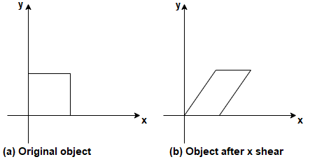
Fig. 2
The transformation matrix for X- shear:
Y’=Y + Shy * X and X’=X
Y-shear:
It preserves the X coordinates and makes changes with the Y coordinates.
The horizontal line of the object slopes toward up or down as shown in the below figure:
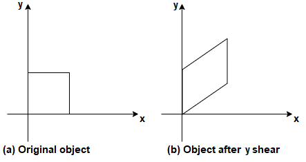
Fig. 3
The transformation matrix for X- shear:
X’=X + Shx * Y and Y’=Y
Windowing
The portion of the screen where the selection and enlarging of the portion of the drawing method is used is called windowing.
The world coordinates are used to select the window.
The window becomes an imaginary box where we select objects or enclose the area of the object.
The size of the window is (0,0) coordinates which is a bottom left corner and towards the right side until the window encloses the desired area.
The area on the display device where the window is mapped is called a viewport.
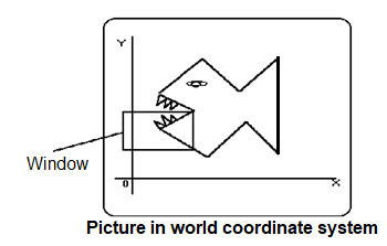
Fig. 4
Clipping
The viewport is a section of the screen where the images are enclosed by the window on the world coordinate system will be drawn.
When a window is placed on the object and parts of the objects can be seen.
The points and the lines that are outside the window are cut off from view.
This process of cutting off parts of the image on the screen is called clipping.
In clipping, we examine the object with each line that comes completely inside the window, completely outside the window, or crosses the window.
If the lines are inside the window, then lines will be displayed, if the lines or points are completely outside the window then it is not displayed.
If the line and the points are crossing the window then the part of the intersection will be taken and the portion which comes inside the window that will be displayed other part will be not displayed.
Below figure shows the clipping process.
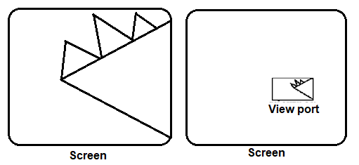
Fig. 5
It is a term that describes a series of transformations.
The data that passed to end up image data being displayed on a device.
The viewing pipeline includes some coordinates as object coordinate, world coordinate, viewing coordinate, normalized coordinates, and device coordinates.
Object coordinate- an individual object that created by the coordinates
World coordinate- several objects into one scene
Viewing coordinate- the viewer after transformation into the coordinates system of the camera
Normalized coordinates- the projection onto a common plane that yields device-independent
Device coordinate- final mapping of normalized coordinates to a specific device
The viewing transformation is the mapping part of the world coordinate scene to device coordinate.
The viewing transformation is also called the window to viewport transformation or windowing transformation.
Following figure 2.7 shows the viewing transformation using a standard rectangle for window and viewport.
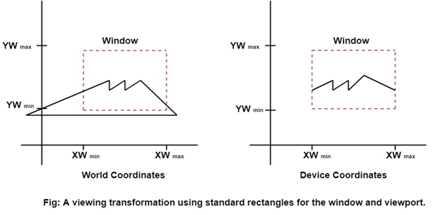
Fig. 6
Following are some steps to perform viewing transformation:
- First, we construct the scene in the world coordinate system using the primitives and attributes.
- To obtain the particular orientation, set up a 2D viewing coordinate system in the window coordinates plane and define a window in a viewing coordinates system.
- After viewing frame established the transformation description comes at world coordinates to view coordinates.
- Define viewport in normalized coordinates.
- Map the viewing coordinates description of the scene to normalized coordinates.
- Finally, all the parts of the picture are enclosed in the device coordinates.

Fig. 7
Key takeaways:
The viewing transformation is the mapping part of the world coordinate scene to device coordinate.
It specifies the position and orientation of the viewport.
It defines the custom utility for VTs in the specialized application.
The procedure which identifies those portions of the picture that are either inside or outside of a specified region of space is referred to as a clipping algorithm.
The region that is clipped is called a clipping window.
The line clipping is the same as the point clipping method.
The line that is outside the window is cut and the line which is inside the window will be displayed.
This algorithm uses the line clipping method.
The minimum coordinates for the clipping region are (XWmin, YWmin) and the maximum coordinates are (XWmax, YWmax).
Below figure 2.9 shows the concept of cohen Sutherland line clipping.
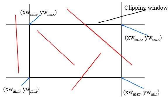
Fig. 8
There are three possibilities for line as-
- The line which is completely inside the window will be accepted.
- The line which is completely outside the window will be discarded.
- The line which is partially inside the window in that the portion which is inside that will be shown and the other part will be discarded.
The 4bits are used to divide the entire region.
These 4 bits represent the top, bottom, top, and left as figure 2.9.1 shows.
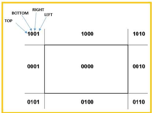
Fig. 9
Following are steps to perform the Cohen Sutherland algorithm which are based on 4 bits that are given above.
- Assign a region code for each endpoint.
- If both endpoints having bits 0000 then that line will be accepted.
- Else perform logical AND operation on the region code.
- If the result is not 0000 then reject the line.
- Else need clipping process
- Choose an endpoint of the line that is outside the window.
- Find the intersection point at the window boundary.
- Replace the endpoints with that intersection points and update the region code.
- Repeat step 2 until we get the clipped line either trivially accepted or trivially rejected.
- Repeat step 1 for other lines.
Key takeaways:
It detects the line whether is it inside the screen or it is outside the screen.
It comes under three categories as a visible, not visible, and clipping case.
The Cohen Sutherland algorithm is a line clipping algorithm that performs an initial test on line to determine whether intersection calculations can be avoided.
It calculates endpoints very quickly and rejects and accepts lines quickly.
It clips the pictures much larger than the screen size.
It is a line clipping algorithm.
It is more effective than the Cohen-Sutherland Line Clipping algorithm.
This algorithm can be extended in three-dimensional clipping.
This is referred to as the fastest parametric line clipping algorithm.
Following are the terms that are used in clipping:
- The parametric equation of the line
- The inequalities describe the range of the clipping window, which determines the intersection between a line and a clip window.
The parametric equation can be shown as,
X=x1 + t(x2-x1)
Y=y1 + t(y2-y1)
Where t is between 0 and 1
The point clipping condition in parametric form,
XWmin <= x1 + t(x2-x1) <= XWmax
YWmin <= Y=y1 + t(y2-y1) <= YWmax
The four inequalities can be expressed as,
Tpk <= qk where k=1,2,3,4
Where p and q can be defined as,
p1= -(x2-x1) q1=x1-XWmin
p2 = (x2-x1) q2=XWmax –x1
p3= -(y2-y1) q3=y1-YWmin
p4= (y2-y1) q4= YWmax-y1
The p value become zero at the line parallel to view window boundary.
When Pk < 0, as t increase line goes from outside to inside
When Pk > 0, the line goes from inside to outside
When Pk = 0, and qk < 0 then the line is trivially invisible because it is an outside view window
When Pk = 0 and qk > 0 then the line is inside the corresponding window boundary
The parameters t1 and t2 can be calculated which defines the part of the line that lies within the clipping rectangle.
When pk<0 maximum (0, qk/pk) is taken
When pk.0, minimum (1, qk/pk) is taken
If t1 > t2 then the line lies completely outside the window and it is rejected.
Key takeaways:
It is the line clipping algorithm after You-Dong Liang and Brian A. Barsky.
It uses the parametric equation of a line and the inequalities which describe the range of clipping window.
It determines the intersection between the line and the clipping window.
With these interactions, it knows which portion of the line should be drawn.
This method is more efficient than the Cohen Sutherland line clipping algorithm.
In some applications, the clipping lines are against the arbitrarily shaped polygons. The Liang Barsky and Cyrus Beck method are used for parametric line equations that can be extended up to convex polygon windows.
Preliminary screening of line segments can be accomplished by processing lines against the coordinate’s extents of polygon clipping.
The parametric line equation can be used in the concave polygon clipping region.
The clipping can be done in a circle or curved boundary region.
The clipping algorithm works slowly for this type of region because intersection calculations involve nonlinear curve equations.
The Liang Barsky can be used for non-rectangular shape clipping where it compares the bounding boxes and uses the inside-outside test to process parametric edges.
The Weiler Atherton algorithm is also used to perform a clipping process on the non-rectangular concave shape.
The Sutherland Hodgeman polygon clipping algorithm is used for polygon clipping.
The polygon can also be clipped by specifying the clipping window.
All the vertices of the polygon are clipped against each edge of the clipping window.
First, the polygon is clipped against the left edge of the polygon window to get new vertices of the polygon.
The new vertices are used to clip the polygon against the right, top, and bottom edge.
While processing an edge of a polygon with a clipping window, an intersection point is found if the edge is not completely inside the clipping window and the partial edge from the intersection point to the outside edge is clipped.
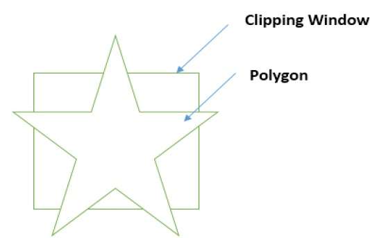
Fig. 10
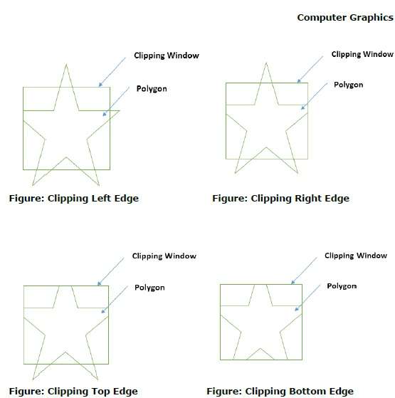
Fig. 11
Key takeaways:
It is a polygon clipping algorithm where the polygon is clipped by specifying the clipping window.
All the vertices of the polygon are clipped against each edge of the clipping window.
First, the polygon is clipped against the left edge of the polygon window to get new vertices of the polygon.
The new vertices are used to clip the polygon against the right, top, and bottom edge.
It is a polygon clipping method where this algorithm also can clip the concave polygons like the Sutherland Hodgeman algorithm.
This algorithm is used in various areas like computer graphics, game development, and others where clipping of polygon is needed.
It allows the arbitrarily shaped clipping polygon or area to be clipped.
This algorithm applies generally in 2D.
This algorithm does not work for itself intersecting polygons.
Steps to be performed to solve the Weiler Atherton polygon clipping algorithm:
- First list the vertices of the clipping region polygon and the subject polygon.
- Label the region of the polygon that is inside or outside the clipping area.
- Find the intersection points and add them into both the list of the polygon.
- Generate the list of inside intersection points where the vector from the intersection to the subsequent vertex of the subject polygon begins inside the clipping region.
- Follow each intersection clockwise around a linked list until the start position is not found.
Example:
The given figure 2.13 shows the polygon which is going to be clipped.
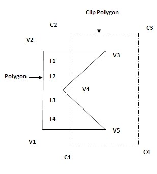
Fig. 12
Here, vertices of the subject polygon are V1, V2, V3, V4, and V5.
C1, C2, C3, and C4 are the clipping polygon region, and I1, I2, I3, and I4 become the intersection points.
In this example we will start traversing from the intersection point I1 while going clockwise we got the sequence as I1, V3, I2.
Here, the leaving intersection occurred hence we go for clip polygon vertex list.
As per the list of intersection points and the vertices of the subject polygon we will traverse it from the downward direction of the polygon.
The process will start again by traversing the intersection point I3.
Then the second traversal starts from I3, V5, and I4.
Again, the leaving intersection points happed check for the list.
Here no other vertex is left hence we will stop the algorithm.
Therefore, the first traversal gives the polygon as I1, V3, I2, I1, and the second traversal gives the polygon as I3, V5, I4, I3.
Key takeaways:
It is a general clipping algorithm used for concave polygons with holes.
It produces multiple polygons.
It follows the inside to outside test of vertices where window boundary in a clockwise direction.
It follows the outside to inside pair of vertices where the polygon boundary is considered.
It is a complex method as compared to line clipping.
In curve clipping, more process is required in linear boundaries.
Assume a rectangular window where the circle is drawn.
If the circle is completely inside then it is considered visible.
If a circle is completely outside then it is discarded.
If the circle cut the boundary line, then it to be a clipping case.
The exterior clipping is the method in curve clipping.
In exterior clipping the opposite process is applied as the outside region is saved and the inside region is discarded.
There are many methods used to clip the text.
The algorithm depends on the generation of the characters.
The simple method shows the completely inside text and the other part is discarded which is known as the all or none method.
If all characters are inside the window, then it is saved but if the string character is outside then the whole string will be discarded.
Another method is if the character that lies on the boundary, then it is discarded completely.
Following figure 2.15 shows the text clipping method properly.
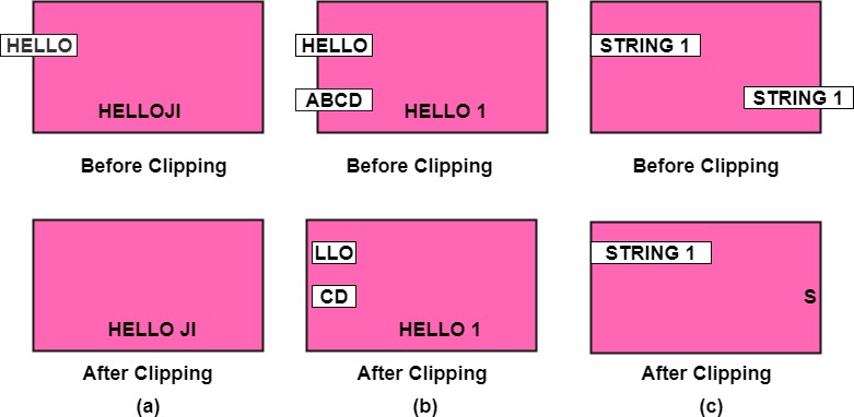
Fig. 13
References:
1. Donald Hearn and M Pauline Baker, “Computer Graphics C Version”, Pearson Education
2. Foley, Vandam, Feiner, Hughes – “Computer Graphics principle”, Pearson Education.
3. Rogers, “Procedural Elements of Computer Graphics”, McGraw Hill
4. W. M. Newman, R. F. Sproull – “Principles of Interactive Computer Graphics” – Tata McGraw Hill.
5. Amrendra N Sinha and Arun D Udai,” Computer Graphics”, Tata McGraw Hill.
6. R.K. Maurya, “Computer Graphics” Wiley Dreamtech Publication.
7. M.C. Trivedi, NN Jani, Computer Graphics & Animations, Jaico Publications
8 Rishabh Anand, Computer Graphics- A practical Approach, Khanna Publishing House
9. Mukherjee, Fundamentals of Computer graphics & Multimedia, PHI Learning Private Limited.
10. Donald Hearn and M Pauline Baker, “Computer Graphics with OpenGL”, Pearson education