Unit - 3
Three Dimensional
The primitives are the building blocks of geometric forms.
These primitives can be used or modify with transformation and Boolean.
Following are 3D geometric primitives.
- Cube
- Cylinder
- Tube
- Sphere
- Torus
- Cone
The most commonly 3D object is represented in the set of the surface polygon that encloses the object interior.
This method is used by many graphics systems.
The set of polygons are used to store object description.
The simplification of surface rendering and display of the object is given by the description of all surfaces in a linear equation.
The polygon surfaces are used in the design and solid modeling application as they are wireframe display.
The polygon surface is used to illuminate the interpolating shading patterns produced by realistic scenes.
The following figure shows the representation of the 3D object.
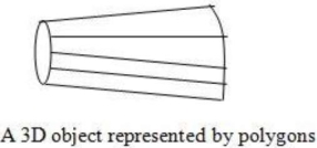
Fig. 1
Following are some transformations in 3D:
3.3.1 Translation
The translation is used for moving an object from one position to another position like in 2D.
There are three vectors in 3D to be changed for the translation process as x, y, z-axis.
In 3D there are also the three translation vectors used.
The translation in the x-direction is represented as tx, in the y-direction ty nad in the z-direction it is represented as tz.
If P (x, y, z) is the point which is going to be translated with the translation vectors (tx, ty, tz) then new vectors will be,
X’=X+tx
Y’=Y+ty
Z’=Z+tz
Following is the matrix for translation:
1 | 0 | 0 | 0 |
0 | 1 | 0 | 0 |
0 | 0 | 1 | 0 |
Tx | Ty | Tz | 1 |
1 | 0 | 0 | Tx |
0 | 1 | 0 | Ty |
0 | 0 | 1 | Tz |
0 | 0 | 0 | 1 |
Or


 matrix representation will be,
X’ 1 0 0 tx X
Y’ = 0 1 0 ty Y
Z’ 0 0 1 tz Z
1 0 0 0 1 1
Following figure shows the translation process in 3D:
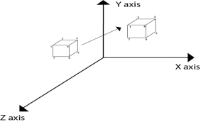
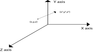
Fig. 2(a) Fig. 2(b)
3.3.2 Scaling
It is used to change the size of object like 2D transformation.
The size can be increased or decreased by using scaling.
If the scaling vectors are the same or equal i.e., Sx=Sy=Sz then it is known as uniform scaling.
If the scaling vectors are different then it is known as differential scaling.
In 3D there are three scaling factors as Sx, Sy, and Sz.
Sx for the x-direction, Sy for the y-direction, and Sz for the z-direction.
Matrix for scaling is shown as follows:

 Sx 0 0 0
0 Sy 0 0
0 0 Sz 0
0 0 0 1
It is mathematically represented as,

 P’=P * S
[X’ Y’ Z’ 1] = [X Y Z 1] Sx 0 0 0
0 Sy 0 0
0 0 Sz 0
0 0 0 1
= [X.Sx Y.Sy Z.Sz 1]
Steps for scaling the object if the object is located at a fixed place.
- Translate the object at the origin
- Scale the object relative to the origin
- Translate again back to the original position
Following figure 3.3.2 shows the scaling in 3D transformation.
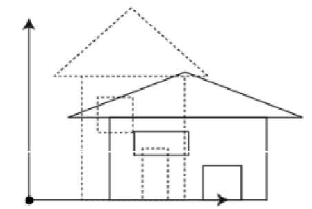
Fig. 3
3.3.3 Rotation
It is used to rotate an object about an angle.
The object can be rotated anticlockwise or clockwise.
This rotation is complex than the 2D rotation.
In this, the axis is also important with the angle of rotation.
The axis can be x, y, or z.
Following figure 3.3.3 shows the rotation about the y-axis:
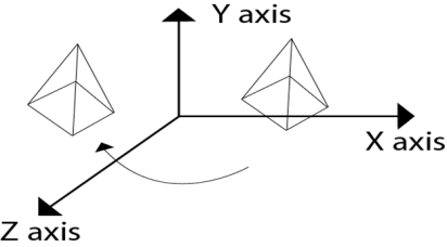
Fig. 4
Rotation matrix are represented as:
1 | 0 | 0 | 0 |
0 | CosꙪ | -sinꙪ | 0 |
0 | SinꙪ | CosꙪ | 0 |
0 | 0 | 0 | 1 |
Rx(Ꙫ)=
CosꙪ | 0 | SinꙪ | 0 |
0 | 1 | 0 | 0 |
-sinꙪ | 0 | CosꙪ | 0 |
0 | 0 | 0 | 1 |
Ry (Ꙫ)=
Rz (Ꙫ)=
CosꙪ | -sinꙪ | 0 | 0 |
SinꙪ | CosꙪ | 0 | 0 |
0 | 0 | 1 | 0 |
0 | 0 | 0 | 1 |
3.3.4 Shearing
The transformation which is used to slant the object is called shearing.
In 3D the shearing is placed on three axes as the X-axis, Y-axis, and Z-axis.
The coordinates are represented in shearing,
X’=X + Shyx * Y+ Shzx * Z
Y’=Y + shxy * X+ Y +Shzy * Z
Z’=Shxz * X + Shyz * Y + Z
Mathematically it is represented as,
P’=P * Sh
The shearing factors in the matrix are represented as,

 Sh= 1 Sh yx Sh zx 0
Sh xy 1 Sh zy 0
Sh xz Sh yz 1 0
0 0 0 1
Following figure 3.3.4 shows the shearing in 3D transformation.
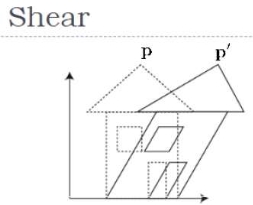
Fig. 5
It is more complex than 2D viewing.
The projection is required to view the 3D object.
The 3D viewing shows some viewing positions as follows.
Front of an object
Behind the object
The middle group of objects
Inside an object
The description of 3D objects must be projected onto the flat viewing surface of the output device.
The clipping boundaries enclose a volume of space.
In 2D, X, and Y coordinates are used but in 3D the extra z coordinate is added.
The 3D computer graphics and their applications are applied in computer games, entertainment, etc.
It is also used in scientific visualization.
3.5.1 Parallel Projection
The parallel projection discards the z coordinate.
The parallel line from each vertex on the object is extended until they intersect the view plane.
The direction of the projection will be specified instead of the center of the projection.
The distance between the project plane and the center of the projection is infinite, in parallel projection.
In parallel projection, the projected vertices are connected to the original object by line segments.
This projection is good for exact measurement but not so realistic.
There two measure types of projection as follows:
- Oblique projection
- Orthographic projection
3.5.2 Oblique Parallel Projection
The projection of the plane and the direction of the projection is not normal in oblique projection.
The object can be view better in oblique projection than orthographic projection.
There are two types of oblique projection as follows:
- Cavalier
- Cabinet
Cavalier Projection:
The cavalier makes the angle 45 to the projection plane.
In cavalier, the projection line is perpendicular to the view plane with the same length as the line itself.
The foreshortening factors for all three principal directions are equal.
Cabinet Projection:
The cabinet makes the angle 63.4 to the projection plane.
In the cabinet, the projection line is perpendicular to the view plane surface with 1/2 length as the line itself.
Both the projections are as follows.
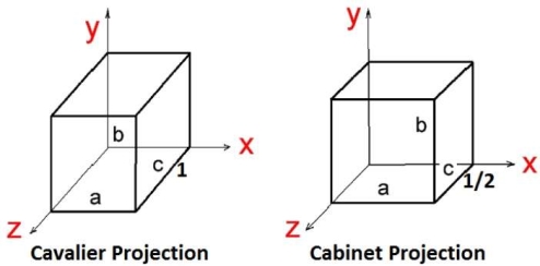
Fig. 6
3.5.3 Orthographic Projection
In orthographic projection, the direction of the projection is normal to the projection of the plane.
There are three types of orthographic projections:
- Front projection
- Top projection
- Side projection
The following figure shows the orthographic projection.
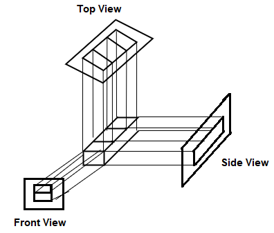
Fig. 7
Isometric Projection:
The object that shows more than one side of the object in orthographic projection then it is known as axonometric orthographic projections.
The isometric projection is the most common axonometric projection.
The projection plane intersects each coordinate axis in the model coordinate system at an equal distance.
The angles of projection are not preserved but parallelism of projections are preserved.
The following figure shows the isometric projection:
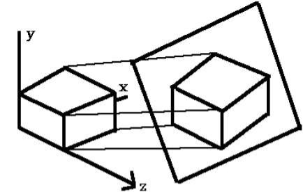
Fig. 8
Diameter Projection:
In diameter projection, two of the three axes of space appear foreshortened.
The direction of viewing is equally foreshortened.
Based on the angle of viewing the attendant scale and angles of presentation are determined.
The scale of the third direction is determined separately.
The dimensional approximation is common in diametric projection.
Trimetric Projection:
In diameter projection, all three axes of space appear foreshortened.
The direction of viewing is unequally foreshortened.
Based on the angle of viewing the attendant scale of three axes and angles of presentation are determined.
The dimensional approximation is common in trimetric projection.
The trimetric perspective is used in trimetric drawings.
3.5.4 Perspective Projection
The distance between the center of the projection and the projection plane is finite in perspective projection.
The distance looks realistic in perspective projection.
The size of the object varies inversely with distance.
The parallelism is not maintained as well as the distance and angles are not preserved in perspective projection.
Distance, angles, and the lines converge at the center of the projection or projection reference point.
There are three types of points in the perspective projection as given below:
- One point: it is simple to draw
- Two-point: it gives a better impression of depth.
- Three-point: it is difficult to draw.
Key Takeaways:
Projection having two types as Parallel and perspective projection.
Parallel projection is the line that is extended from the object and intersects the view plane.
Parallel projection having two types as oblique and orthographic parallel projection.
Perspective projection is the distance between the center of the projection and the project plane infinite.
The 3 D clipping is complex than 2D clipping.
There are two common clipping method in graphics as-
Rectangular parallelepiped volume- box used for parallel projection
Truncated pyramidal volume- used for perspective projection
These volumes having six sides like a top, bottom, left, right, hither (near), yon (far).
The 2D concepts are extended in 3D clipping by these 6 sides and 6-bit code instead of 4-bit code.
The position of bits are as follows:
Bit 1=1 endpoint to the left of the volume
Bit 2=1 endpoint to the right of the volume
Bit 3=1 endpoint to the below of the volume
Bit 4=1 endpoint to the above of the volume
Bit 5=1 endpoint to the front of the volume
Bit 6=1 endpoint to the behind of the volume
Otherwise, the bit is set as 0.
The following figure shows the rectangular parallelepiped volume which is a box used for parallel projection and the Truncated pyramidal volume which is used for perspective projection.
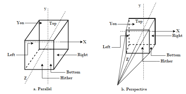
Fig. 9
References:
1. Donald Hearn and M Pauline Baker, “Computer Graphics C Version”, Pearson Education
2. Foley, Vandam, Feiner, Hughes – “Computer Graphics principle”, Pearson Education.
3. Rogers, “Procedural Elements of Computer Graphics”, McGraw Hill
4. W. M. Newman, R. F. Sproull – “Principles of Interactive Computer Graphics” – Tata McGraw Hill.
5. Amrendra N Sinha and Arun D Udai,” Computer Graphics”, Tata McGraw Hill.
6. R.K. Maurya, “Computer Graphics” Wiley Dreamtech Publication.
7. M.C. Trivedi, NN Jani, Computer Graphics & Animations, Jaico Publications
8 Rishabh Anand, Computer Graphics- A practical Approach, Khanna Publishing House
9. Mukherjee, Fundamentals of Computer graphics & Multimedia, PHI Learning Private Limited.
10. Donald Hearn and M Pauline Baker, “Computer Graphics with OpenGL”, Pearson education